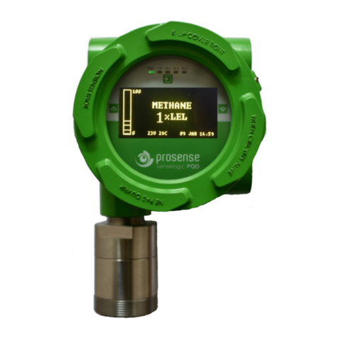
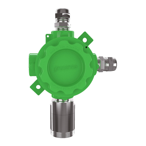
Prosense Safevader Series User manual

PRS-UM-SV-EN-Rev1.0-16.12.2022 Page 2/ 41
WARNING!
READ THIS INSTRUCTION FIRST!
This manual must be carefully read by all persons who have or will have the responsibility for
installing, using or servicing this product.
Like any equipment, this product will perform as designed only if installed, used and serviced
in accordance with the manufacturer’s instructions. Otherwise, it could fail to perform as
designed and persons who rely on this product for their safety could suffer severe personal
injury or death.
The warranties made by Prosense with respect to this product are voided if the product is not
installed, used and serviced in accordance with the instructions in this user guide. Please
protect yourself and other by following them.
CAUTION
This product has been tested and approved for use in safe areas and should not be used in
hazardous areas. Any device modification, improper installation, or use in a faulty or
incomplete configuration will render warranty and product certifications invalid.
Important Remark
The detector has been factory-tested before delivery. The commissioning has to be
terminated by a function test of the complete gas detection system.
ELECTROSTATIC HAZARD - CLEAN ONLY WITH A DAMP CLOTH!

PRS-UM-SV-EN-Rev1.0-16.12.2022 Page 3/ 41
Contents
Safety Information......................................................................................................................................5
Strictly follow the Instructions for Use...............................................................................................6
Maintenance.......................................................................................................................................6
Use in areas subject to explosion hazards ......................................................................................... 6
Liability for proper function or damage .............................................................................................6
Intended Use ......................................................................................................................................6
Introduction................................................................................................................................................8
Detector body............................................................................................................................................. 9
Installation..................................................................................................................................................9
Mounting the detector.............................................................................................................................10
Electrical connections...............................................................................................................................11
Detector grounding ..................................................................................................................................13
SafeVader Outputs ...................................................................................................................................14
4-20 mA output: ...................................................................................................................................14
RS485 serial communication output: ...................................................................................................15
Relay Outputs: ......................................................................................................................................15
System Status ...........................................................................................................................................16
Indication of measured values .........................................................................................................17
Warmup............................................................................................................................................17
Fault..................................................................................................................................................17
Alarm ................................................................................................................................................17
Calibration ........................................................................................................................................18
Underrange.......................................................................................................................................18
Overrange.........................................................................................................................................18
Analogue Output State:....................................................................................................................19
Switching Output State.....................................................................................................................20
Commissioning .........................................................................................................................................21
Commissioning SafeVader....................................................................................................................21
Detector Settings......................................................................................................................................22
Entering the menu:...............................................................................................................................22
Menu structure.....................................................................................................................................23
Alarm Settings ......................................................................................................................................24
Configure ..............................................................................................................................................25
Change Modbus address ..................................................................................................................25
Change Analogue Output .................................................................................................................25
Display Parameters...............................................................................................................................26
Change Language..............................................................................................................................26
Change Zero Suppression .................................................................................................................26
Change password .............................................................................................................................27

PRS-UM-SV-EN-Rev1.0-16.12.2022 Page 4/ 41
Information Menu options ...................................................................................................................28
Display Measurements.....................................................................................................................28
Display Transmitter information ......................................................................................................28
Display Sensor information ..............................................................................................................28
Test Menu Options...............................................................................................................................29
Run Inhibit test .................................................................................................................................29
Run Display test................................................................................................................................29
Run Relay test...................................................................................................................................29
Run Analogue Output test................................................................................................................30
Calibration ................................................................................................................................................31
Set Reference Gas details.....................................................................................................................32
Zero Calibration....................................................................................................................................33
Span Calibration ...................................................................................................................................33
Cancel Calibration.................................................................................................................................34
Maintenance ............................................................................................................................................35
Proactive maintenance:........................................................................................................................35
Operational Life:...................................................................................................................................35
Sensor module replacement: ...............................................................................................................35
Detector Transmitter board replacement:...........................................................................................36
Display Module replacement: ..............................................................................................................36
Fault Status Codes: ...................................................................................................................................37
General specification................................................................................................................................38
Electrical Specifications: ...................................................................................................................38
Detector Body Specifications: ..........................................................................................................38
Environmental: .................................................................................................................................38
Default Configuration:......................................................................................................................39
Warranty statement.................................................................................................................................40
Exclusions .........................................................................................................................................40
Warranty Limitation and Exclusion ..................................................................................................40
Limitation of Liability........................................................................................................................41

PRS-UM-SV-EN-Rev1.0-16.12.2022 Page 5/ 41
Safety Information
FOR SAFETY REASONS THIS EQUIPMENT MUST BE OPERATED AND SERVICED BY QUALIFIED
PERSONNEL ONLY. READ AND UNDERSTAND INSTRUCTION MANUAL COMPLETELY BEFORE
OPERATING OR SERVICING.
CAUTION
A HIGH OFF-SCALE READING MAY INDICATE EXPLOSIVE CONCENTRATION.
Observe these precautions:
•To minimize the risk of electrostatic charge, provision shall be made for adequate grounding and
equipment shall be installed in such a manner so that accidental discharge shall not occur.
•When Prosense SAFEVADER reaches the end of its life, it should be disposed of in accordance
with local regulations.
•Do not use cleaning solvents or abrasives to clean the gas detector.
•Do not attempt to modify the product in any way from the manufacturers design or
specification. Warranty will be void and malfunction of the gas detector may result.
•Use only genuine spare parts and accessories with Prosense SAFEVADER. Malfunction may result
if non-standard parts are used.
WARNING
•Prosense SAFEVADER is designed for installation and use in safe areas.
•Installation must be in accordance with the recognized standards of the appropriate authority in
the country concerned.
•Access to the interior of the detector, when carrying out any work, must only be conducted by
trained personnel.
•Before carrying out any work ensure local regulations and site procedures are followed.
•In order to maintain electrical safety, the product must not be operated in atmospheres with more
than 21% oxygen. Oxygen deficient atmospheres (Combustible: less than 10%V/V, Toxic: less than
6%V/V) may suppress the sensor output.
•Never attempt to open the enclosure or replace/refit the sensor in potentially hazardous
atmospheres or while power is still applied to the transmitter.
•The detector must be earthed/grounded for electrical safety and to limit the effects of radio
frequency interference. Earth/ground points are provided inside the unit. The internal grounding shall
be used as the primary equipment ground.
•Ensure that all screens/instrument earth/clean earth wiring is earthed/grounded at a single point
(either at the controller or detector, BUT NOT BOTH) to prevent false readings or alarms that may occur
due to potential earth/ground loops.
•Take care when handling sensors as they may contain corrosive solutions. Do not tamper with or in
any way disassemble the sensor.
•Do not expose to temperatures outside the recommended ranges.
•Do not expose sensors under storage conditions to organic solvents or flammable liquids.
•At the end of their working life, replaceable electrochemical sensors for oxygen and toxic gas must
be disposed of in an environmentally safe manner. Disposal should be according to local waste
management requirements and environmental legislation.

PRS-UM-SV-EN-Rev1.0-16.12.2022 Page 6/ 41
•Electrochemical sensors should NOT be incinerated as this action may cause the cell to emit toxic
fumes.
•Refer to the local or national regulations relative to the installation at the site. For Europe see
EN60079-29-2, EN60079-14, EN45544-4 and EN61241-14. For installations in North America, the
National Electrical Code (NFPA 70) should be strictly observed. All the appropriate local and national
regulations should be observed.
•The pellistors used in the catalytic flammable gas sensor can suffer from a loss of sensitivity when
in the presence of poisons or inhibitors, e.g. silicones, sulphides, chlorine, lead, or halogenated
hydrocarbons.
Ensure that this Operating Manual is read and understood BEFORE installing / operating /
maintaining the equipment. Pay particular attention to Warnings and Cautions. All document
Warnings are listed here and repeated where appropriate at the start of the relevant chapter(s)
of this Operating Manual. Cautions appear in the sections/sub-sections of the document where
they apply.
Strictly follow the Instructions for Use
Any use of the detectors requires full understanding and strict observation of these instructions.
The detector is only to be used for purposes specified here.
Detectors must be protected from extreme vibration and direct sunlight in hot environments
as this may cause the temperature of the detector to rise above its specified limits and cause
premature failure.
Maintenance
It is recommended to obtain a service contract Prosense to carry out all repairs. Only authentic
Prosense spare parts must be used, substitute components may invalidate the certification and
warranty of the detector. Maintenance and calibration operations must only be performed by
qualified service personnel.
Use in areas subject to explosion hazards
Use in areas subject to explosion hazards is not permitted.
Liability for proper function or damage
The liability for the proper function of the detector is irrevocably transferred to the owner or
operator to the extent that the detector is serviced or repaired by personnel not employed or
authorized by Prosense or if the sensing part is used in a manner not conforming to its intended
use. Prosense cannot be held responsible for damage caused by non-compliance with the
recommendations given above. The warranty and liability provisions of the terms of sale and
delivery of Prosense are likewise not modified by the recommendations given above.
Intended Use
The SAFEVADER series detectors are intended to be used for stationary, continuous monitoring
for combustible gas/air or vapour/air mixtures below the Lower Explosion Limit (LEL) and toxic

PRS-UM-SV-EN-Rev1.0-16.12.2022 Page 7/ 41
gas/air mixtures in particule per million (PPM) and Oxygen and CO2 in volume (VOL) units. The
enclosure protection is IP 65. For the determination of the measuring range and operating
conditions, the label on the detector should be consulted.
Not to be used in oxygen enriched atmospheres.
In conjunction with the central controllers Prosense detectors with preadjusted alarm
thresholds audible and visible alarm devices or automatic countermeasures can be activated
before the detected gases or vapours can form dangerous flammable or toxic mixtures with air.
SAFEVADER series with pellistor sensor for flammable gas detectors are designed to detect
gases or vapours in air and not inert or oxygen deficient atmospheres. Please be alerted in
following special conditions may have impact on measuring function due to the nature of
measuring method:
1. Very high gas concentrations
The measuring method of SAFEVADER series detector based on heat produced by reaction on
the oxidation of a flammable gas when pellistor sensor used. There is not enough oxygen in the
sensor to perform oxidation process correctly in case of high gas concentrations. Hence the
measuring signal decreases at high gas concentrations and even can lead to measuring signal
within the measuring range again. In case of high flammable gas concentration, do not reset
latching alarms without having ensured a safe condition in the environment via performing
necessary checks.
2. Minimum oxygen concentration
The measuring principle of heat of reaction needs a minimum oxygen concentration of 12 % by
volume for SAFEVADER series detector with pellistor sensor; otherwise the measuring values
will be too low because of oxygen deficiency.
3. Long-term gassing with methane at very low temperatures
If the Prosense SAFEVADER series flammable gas detectors with pelistör sensor are operated
applying with methane at very low temperatures, the measuring signal at long term exposition
may decrease after alarm activation and may lead to misinterpretation.
If a gas alarm occurs, necessary actions need to be taken immediately. The decrease of the
measuring signal should not mean that the gas concentration has been decreased. We
recommend to keep alarms on the associated controllers and not to reset these alarms without
performing measurement with an independent gas detector to make sure conditions are safe.
4. Avoid exposure to Silicon complex
Prosense pellistor sensors high level of resistance to catalytic poisons like Hydrogen Sulphide
(H2S) and Silicones such as HMDS (HexaMethylDoSiloxane). But it is not suitable to use in
environments which continous exposure of poisoning elements.

PRS-UM-SV-EN-Rev1.0-16.12.2022 Page 8/ 41
Introduction
The Prosense comprises a gas detector body and a choice of sensors heads for detecting
flammable gases, toxic gases and oxygen. The construction of Prosense SAFEVADER Series
detectors allows it to be used in areas not classified as hazardous.
Prosense SAFEVADER Series detectors can be configured with a wide range of different sensors
may be used to detect a broader range of target gases. The detector provides an industry
standard 3-wire, 4-20mA output for connection to a dedicated gas detection control system or
PLC. It can also provide RS485 serial communication with integrated onboard devices.
Prosense SAFEVADER series provides on board three relays to use as switching output which
are FAULT, ALARM1 and ALARM2. Relay switching outputs can be used for controlling external
equipment e.g. alarms, sirens, valves or switches.
Prosense SafeVader detectors comprises of the main parts as shown below:
Diagram 1: Exploded view of SafeVader detector
Encoure Cover
Main board
PCB Cover
Field cable entry x2
Connectors
Sensor module connector
Mounting hole
Sensor module
Display board
Display
Encoure body

PRS-UM-SV-EN-Rev1.0-16.12.2022 Page 9/ 41
Detector body
The detector enclosure has two cable entries located at the bottom of enclosure for connecting
the power source, signal output and relay contacts to associated signalling equipment. There
are two mounting holes incorporated into the transmitter housing.
Diagram 2: Detector body and size (mm)
Installation
Gas detectors should be mounted where a potential hazard of gas is most likely to be present.
The following points should be noted when locating gas sensors.
•When locating detectors consider the possible damage caused by natural events e.g. rain or
flooding.
•Consider ease of access to the gas detector for functional testing and servicing.
•Consider how escaping gas may behave due to natural or forced air currents.
Note: The placement of gas detectors should be determined following the advice of experts
having specialist knowledge of gas dispersion, experts having knowledge of the process plant
system and equipment involved safety and engineering personnel. The agreement reached on
the location of detectors should be recorded.
Each gas has different nature depending on their density. The density of which is lower than air,
such as hydrogen, methane or ammonia the sensor head must be located above a possible leak
or at the highest points at which major concentrations of gas may be found. The gases and
vapours with a density greater than air, the sensor head must be installed beneath a possible
leak or at the lowest points at which such gases and vapours may be present.

PRS-UM-SV-EN-Rev1.0-16.12.2022 Page 10 / 41
Mounting the detector
The detector must be mounted vertically as the sensor pointing forward. Detector has to be
mounted such that the sensor's gas entrance area. The install location
•should be isolated from vibration, direct sun light and have temperature stability
•avoided external influences such as splashing water, oil, corrosive aerosols
•should have at least 30 cm free space beneath the sensor head to provide accessibility for
calibration work.
•should be in air flow between possible leak or collection point and possible source of ignition.
Prosense do not recommend installing detectors to:
•directly above a cooking unit,
•directly above a sink unit,
•close to an extractor unit,
•outdoor without protection against the rain,
•in places where temperature is outside the admissible operating range,
•corrosive environments,
•inside air vents.
•environments where silicon can be found.
Prosense SAFEVADER series detector has two mounting holes on detector body to fix detector
directly to a surface:
Diagram 3: Mounting holes
Mounting hole
Mounting hole

PRS-UM-SV-EN-Rev1.0-16.12.2022 Page 11 / 41
Electrical connections
CAUTION
The wiring procedures in this manual are intended to ensure proper functioning of the device
under normal conditions. However, because of the many variations in wiring codes and
regulations, total compliance to these ordinances cannot be guaranteed. Be certain that all
wiring complies with the NEC as well as all local ordinances. If in doubt, consult the authority
having jurisdiction before wiring the system. Installation must be done by a properly trained
person.
CAUTION
Observe precautions for handling electrostatic sensitive devices.
SAFEVADER Series Detector must be powered by a SELV power supply.
The SAFEVADER Series Detector shall be supplied by an isolated power source which fulfils
the requirements of:
•Limited-Energy Circuit in accordance with UL/CSA 61010-1,
•Limited Power Source (LPS) in accordance with (UL/CSA 60950-1 or EN 62368-1, Annex Q)
or
•Class 2 supply source which complies with the National Electrical Code (NEC), NFPA 70,
Clause 725.121 and Canadian Electrical Code (CEC), Part I, C22.1.
Prosense detectors can operate between 12 - 24 VDC. The detector designed to provide 4-20
mA current output signal. It is also possible to get voltage value via using an additional resistor.
Table-4 gives recommended resistor specifications to get correct voltage output from detector
depending of the desired signal level:
Detector Power VDC Resistor Signal level (4mA – 20mA)
12 VDC – 24 VDC 250 Ω, tolerance %1 1 VDC – 5 VDC
12 VDC – 24 VDC 500 Ω, tolerance %0,1 2 VDC – 10 VDC
Table 1: Detector power and the output resistor
Please consider the cable length when performing installation in the field. The Prosense
detector requires a power supply between 12VDC and 24VDC. Make sure that a minimum 12
VDC supply available at the detector entrance and consider the voltage drop due to cable
resistance in case of long distance applications. The maximum loop resistance in the field cable
is calculated as follows:
R loop = (V controller – V detector min) / I detector

PRS-UM-SV-EN-Rev1.0-16.12.2022 Page 12 / 41
Example;
Diagram 4: Field cabling
The controller or power supply is supplying a nominal 24VDC (V controller), the detector
minimum allowable voltage is 12VDC (V detector min), therefore the maximum allowable
voltage drop between the controller and detector is 12VDC; this means a voltage drop of 6V
in each core (V+ core and V- core).
Minimum power consumption of the detector without any optional module is 1W. The current
required to drive the detector at the minimum voltage is
(I = P / V) : 1.0 / 12 = 85mA (I detector).
Maximum power consumption of the detector when optional relay modules installed and all
relays are active is 4.0W. The current required to drive the detector at the minimum voltage
is (I = P / V) : 4.0 / 12 = 335 mA (I detector).
So, the maximum field cable loop resistance (R loop) = 12 / 0.335 = 36 Ohms, or 18 Ohms per
core, (allowing for component variations, losses, etc.).
The following tables show the maximum cable distances between the controller and
transmitter assuming a voltage drop of 6V in each core and for different cable parameters.
The table values are examples only and actual cable parameters and source power supply
voltage for the application should be used to calculate the maximum cable distance allowed
at the installation site.
Typical cable data for detector with relay module given in Table 5:
Cable size
Cable type
Cable resistance
Maximum Cable length (L)
(cross sectional area)
nearest equivalent
Ω/km
Meters
0.5mm2
20AWG
36.8 Ω/km
~400
1.0mm2
17AWG
19.5 Ω/km
~700
1.5mm2
16AWG
12.7 Ω/km
~1100
2.0mm2
14AWG
10.1 Ω/km
~1400
2.5mm
2
13AWG
8.0 Ω/km
~1800
Table 2: Typical cable details and maximum distance for cabling
The use of industrial grade, suitably shielded field cable is recommended. Depending on the
distance between signal received or control panel and detector 0.5 to 2.5 mm2 (20 to 13 AWG)
conductors can give better results. Ensure the cable gland is installed correctly and fully
tightened.

PRS-UM-SV-EN-Rev1.0-16.12.2022 Page 13 / 41
Detector grounding
Internal Ground connection: Each detector has grounding screw which utilizes grounding for
detector main PCB to detector body. The screw should be located correctly and fixed for all
times. In case of any maintenance activity this screw should be checked and fixed to make sure
for proper grounding.
Diagram 5: Detector internal grounding screw location
Internal grounding screw location should be reserved for grounding cable and not used for any
other purpose.
Minimum internal earth size must at least equal the incoming conductor size (i.e
1.5mm2live/neutral = minimum of 1.5mm2 earth too).
Cable and Earth/Ground regimes
Effective Earth/Ground bonding is important to ensure good EMC and RFI immunity. The
following diagram show example of how to earth/ground bond the cable at enclosures. The
same principles apply to conduit installations. These bonding techniques provide good RFI/EMC
performance. Earth/ground loops must be avoided to prevent the risk of false signal variation.
Diagram 6: Grounding
The Earth Screen of the field cable should be “tied to Earth” or connected to Ground at one
point only. It is common practise to adopt a STAR EARTH connection regime where all
instrumentation Screens are connected at one common point. The Screen at the other end of
the cable should be “parked” or terminated into a blank terminal.
Grounding screw location

PRS-UM-SV-EN-Rev1.0-16.12.2022 Page 14 / 41
SafeVader Outputs
Prosense detectors preconfigured to provide signal from analogue and digital output depending
on the detector and gas type. Detector Main board and connection details given in Diagram-11:
Diagram 7: Detector main board connections
Detector connections are listed in Table-6:
Port
Usage
V +
Power input (+) 12VDC – 28VDC
V-
Power input
S
Current Output Signal (4mA – 20mA)
A
RS485-A Serial connection port A
B
RS485-B Serial connection port B
C
Common COM port for All Relay outputs
F
Fault relay output
A1
Alarm-1 Relay output
A2
Alarm-2 Relay output
Table 3: Detector output ports and their usage
The Prosense SafeVader detector has 4-20mA analogue output, RS485 Modbus serial
communication output and switching output features on main board. It is possible to use all
outputs simultaneously.
4-20 mA output:
Prosense SafeVader detectors can be connected to control panels on the market having 4-20mA
input signal. Signal wiring from detector and the control panel should be carried out by shielded
cables. Wires cross section depends on the distance between the control panel and the
detector. The details given in power cabling are valid for signal output as well.
V+ V- S AB C F A1 A2

PRS-UM-SV-EN-Rev1.0-16.12.2022 Page 15 / 41
Please avoid any interruption in case any junctions on wires. The shield is to be grounded from
the control panel side only and never connect the shield to the detector. Please make sure
clutching or crimping apparatus are not loosened or oxidized.
The analogue signal output levels can be adjusted in predefined range given below:
Status
Value/Setting
Default Setting
Fault
1 mA to 3 mA
2.0 mA
Warm-up
1 mA to 4 mA
3 mA
Calibration mode
1 mA to 4 mA
3mA
Normal gas measurement
4.0 mA to 20.0 mA
4.0 mA to 20.0 mA
Overrange
21.0 – 22.0 mA
22.0 mA
Table 4: Detector default configuration details
RS485 serial communication output:
Prosense SAFEVADER series detector has RS485 serial communication output on main board.
User should prepare two wire additional cables when RS485 communication used. To use the
detector with RS485 serial communication, a four-wire connection should be done which are
energy input (V +, V-) ports and RS485 (A, B) ports. If both analog current output and RS485
serial communication terminals are to be used at the same time, a five-wire connection must
be made to connect the terminals on both sockets (V +, V-, S, A, B). The total length of the
connection line should not exceed 800 meters. The wiring for detectors utilized with RS485
board should be done by using connection cable EIA RS485 2 core wires with section 0.22 / 0.35
mm2 and shielded. Nominal capacity between the wires should be < 50pF/m and nominal
impedance 120 Ohms.
Detectors will be wired in daisy chain (bus) mode. We recommend not using star mode
connection due to negative impact of interference. Each detector should have unique address
number in the chain. The detectors would not be recognised by control panel if same address
given to them. The address of detector can be adjusted via using display menu. Detectors can
be assigned to use addresses from 1 to 247 (including 247). Address zero (0) cannot be used by
detectors.
Relay Outputs:
Prosense SafeVader detectors have three relay outputs to generate switching output in case of
Fault and defined level adjustable two alarms named as Alarm-1 and Alarm-2. The relay outputs
set to NO (Normally Open – De-Energised) position at factory. All relays use same common port
marked with C label and all common connections are shortcircuited.
The Fault relay is set to NO (Normally Open – Energised). It will be de-energized in case of power
failure. This helps user to easily identify any power outage on detector side.
The alarm levels are also adjustable via using menu steps on display.
For oxygen detectors Alarm 1 Relay output predefined to alert Low level Oxygen status and
Alarm 2 Relay output predefined to monitor High level Oxygen status.

PRS-UM-SV-EN-Rev1.0-16.12.2022 Page 16 / 41
System Status
The Prosense SafeVader detector has a screen to show status messages and measurement
levels online. Also it has three LEDs to show power, fault and alarm status. If equipment is in
normal condition the green power LED will blink with 1 second period and screen will show the
gas that detector measuring, current level of gas detector measuring.
Diagram 8: SAFEVADER Series Detector Displya and LEDs
Default display screen is used to show gas level as a text and bar graph, detector state and
subsidiary messages such as fault, alarm 1 or overrange. The detector special state messages
and related LED status for each special state are also shown;
SafeVader Series Visual Indications
Status
Message
Power (Green)
Fault (Yellow)
Alarm (Red)
Power-on
Self Test
Flashing Green
Warm-up
Warm-up
Flashing Green
Flashing Yellow
Normal
Normal
Flashing Green
Fault
Fault
Flashing Green
Solid Yellow
Calibration
Calibration
Flashing Green
Flashing Yellow
Underrange
Fault
Flashing Green
Solid Yellow
Alarm 1
Alarm 1
Flashing Green
Solid Red
Alarm 2
Alarm 2
Flashing Green
Solid Red
Overrange
Overrange
Flashing Green
Flashing Yellow
Solid Red
Table4: SafeVader Series visual indications
Power LED
Fault LED
Decrease / Down Button
Increase / Up Button
Alarm LED
Enter / OK Button
Display

PRS-UM-SV-EN-Rev1.0-16.12.2022 Page 17 / 41
Indication of measured values
Display screen shows the concentration level of the target gas in two ways. In the first, a
numeric value is shown in the middle of the display in the units selected (PPM, %LEL, %VOL).
The second concentration display is shown in the form of a bar graph representing the current
concentration against full scale and in relation to the defined alarm levels.
Warmup
The detector will need to warm-up to be ready when power applied. Warm-Up period takes 1-
2 minutes depanding on the sensor and during this time WARMUP status messages shown on
upper right side of the screen. Also Fault LED will be lit.
User must wait till end of the warm-up period to see actual status of the detector.
Fault
If detector is in fault condition Fault LED will be lit, screen show fault message and the detector
analogue output gives 2mA on S port. If detector could not get enough power (lower than 12
VDC) it will also raise fault status.
Detector also provides key information about fault reason and details. They are listed at Fault
status codes section.
Alarm
Equipment has LED indication on the display module for alarm levels which are Alarm-1, Alarm-
2 and Alarm-3. The Alarm-1 and Alarm-2 is integrated to relay module and equipment can
WARMUP
METHANE
0%LEL
FAULT
METHANE
0%LEL
METHANE
8 %LEL

PRS-UM-SV-EN-Rev1.0-16.12.2022 Page 18 / 41
provide switching output for defined alarm levels. Alarm-3 is only visual alarm and it is not
integrated to relay module. Hence it is not possible to get switching output for Alarm-3. In case
of an alarm, related alarm LED will lit and alarm information will be shown on the screen:
Calibration
Equipment shows countdown messages during the calibration. Equipment shows calibration message
on display only in case user exited from menu during the calibration:
Underrange
Equipment detects underrange condition and set fault state where Fault LED will be lit, screen
show fault message and the detector analogue output gives 2mA.
Overrange
Equipment provides overrange condition in case the measured gas level over the measurement
range. All Alarm LEDs and Fault LED will be lit, screen show Overrange message and the detector
analogue output gives 22mA. Overrange status on RS485 MODBUS output. If relay module is
installed all relays Fault, Alarm-1 and Alarm-2 will be activated. The status will not change
without user intervention even the gas concentratin returns to normal level. It is necessary to
power-cycle detector to reset status by user intervention.
When user reset detector after environmental conditions retrun to normal, detector will perform all
self-test and hardware test steps following reset. User can see detector status after reset. If detector
returns to normal no additional step is required.
ALARM
AL2
METHANE
15 %LEL
CALIBRATION
METHANE
0%LEL
ALARM
OVRNG
METHANE
>100 %LEL

PRS-UM-SV-EN-Rev1.0-16.12.2022 Page 19 / 41
Analogue Output State:
Analogue output of equipment provides state information to external devices via current level.
The output provides signal between 0- 22mA:
•Equipment provides meaningful measurment level between 4-20mA current level. The
external device must evaluate 4-20mA current level as measurement level information. The
evaluation of measuement level regarding a dangerous gas concentration must be performed
by an external device.
•Equipment provides 0-2mA current level when it detects any internal error. The external
device must evaluate 0-2mA current level as fault condition.
•Equipment provides 20-22mA current level as overrange state indication. The external
device must evaluate 20-22mA current level as overrange condition which is a dangerous gas
concentration.
State details and indications are given in below tables:
SAFEVADER Analogue output states and indications
Signal
Meaning
Output(mA)
Power LED
Fault LED
Alarm
LED
Display
Warm-up
Device is working and waiting for
sensor stabilization after power-
on. Actual measurement level is
not used to provide measurement
result or alarm generation.
3
blinking
blinking
off
Warm-up
Fault
Device is in fault condition, not
performing measurement
<2
blinking
solid
off
Fault
Calibration
Device is working and performing
calibration for sensor. Actual
measurement level is not used to
provide measurement result or
alarm generation.
3
blinking
blinking
off
Calibration
Normal
Device is performing
measurement
4-20
blinking
off
off
Measurem
ent level
Alarm
Measured gas level is higher than
defined alarm level
4-20
blinking
off
on
Alarm
Overrange
Measured gas level is higher than
measurement range
20-22
blinking
blinking
on
Overrange
Underrange
Measured gas level is deviated
tha minimum allowed level
<2
blinking
solid
off
Fault
Table 5: SAFEVADER Analogue output states and indications

PRS-UM-SV-EN-Rev1.0-16.12.2022 Page 20 / 41
Switching Output State
In normal operation fault relay is in switched off position, only when the fault relay coil is
energized (contact closed) are the output states valid. The evaluation of the fault relay must be
performed by an external device.
Alarm Relay-1
Indicate if the measured concentration of gas is greater than alarm 1 on-threshold by energising
the first normally energised alarm relay, with the relay response following the calculated gas
level with a delay of no more than 5 second.
Alarm Relay-2
Indicate if the measured concentration of gas is greater than alarm 2 on-threshold by energising
the second normally energised alarm relay, with the relay response following the calculated gas
level with a delay of no more than 5 second.
Fault relay output
Fault relay should be designed as closed circuit / de-energise to trip principle and provide device
state information. As it is a switching output it has two states and behaves as given in below
table:
Status Output(mA)
Fault Relay
Alarm 1 Relay
Alarm 2 Relay
Energy (Coil)
Circuit (Out)
Energy (Coil)
Circuit (Out)
Energy (Coil)
Circuit (Out)
Power-off
0
De-energized
Contact close
De-energized
Contact open
De-energized
Contact open
Warm-up
3
De-energized
Contact close
De-energized
Contact open
De-energized
Contact open
Fault
2
De-energized
Contact open
De-energized
Contact open
De-energized
Contact open
Calibration
3
De-energized
Contact close
De-energized
Contact open
De-energized
Contact open
Zero gas
4
Energized
Contact open
De-energized
Contact open
De-energized
Contact open
Alarm-1 level
Adjustable
Energized
Contact open
Energized
Contact close
De-energized
Contact open
Alarm-2 level
Adjustable
Energized
Contact open
Energized
Contact close
Energized
Contact close
Full Scale Gas
20
Energized
Contact open
Energized
Contact close
Energized
Contact close
Over-range
22
Energized
Contact close
Energized
Contact close
Energized
Contact close
Under-range
2
De-energized
Contact close
De-energized
Contact open
De-energized
Contact open
Table 6: SAFEVADER Series Switching output states and indications
Other than given states the detector is working fine and fault relay will be energised and relay
contact will be open circuit.
Table of contents
Other Prosense Gas Detector manuals
Popular Gas Detector manuals by other brands
GDS
GDS Defender Technical sheet
Macurco
Macurco DMK-1 Installation and operation instructions

Elektrotechnik Schabus
Elektrotechnik Schabus GAS ALARM GX-B1 operating instructions

Evikon
Evikon PluraSens E2638 Series user manual
IME
IME Milesight GS101 user guide
De Nora
De Nora Capital Controls CHLORALERT T17CA4000 Series instruction manual
Pilot Communications
Pilot Communications 2011319/716/12 Operation and maintenance manual
Sensitron
Sensitron SMART3G Short installation manual
TUYA
TUYA CH4 user manual
New Cosmos Electric
New Cosmos Electric XP-3000II Series instruction manual

HST
HST HD105 user guide

LINNEPE
LINNEPE TriGasAlarm instruction manual

