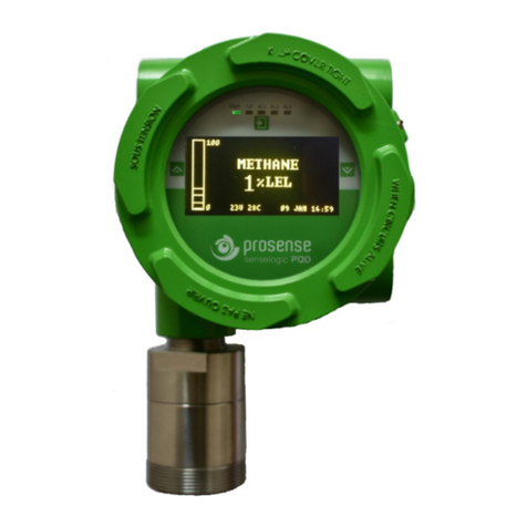
Prosense P Series User manual

PRS‐UM
‐P‐EN‐Rev.0
PR
O
I
1‐08.2018
O
SE
N
nstal
l
Yukar
ı
Tel:(
9
N
SE P
l
atio
n
Prosense
ı
Mah.Har
m
9
0)216306
ww
w
Seri
e
n
and
Teknoloji
S
m
ansok.N
o
7788Faks
w
.prosense
.
e
s Ga
User
S
an.Ltd.Şt
i
o
:42Kartal
:(90)2164
7
.
com.tr
s Det
Man
u
i
.
İstanbul
7
38129
ecto
r
u
al
1
r

2
PRS‐UM‐P‐EN‐Rev.01‐08.2018
WARNING!
This manual must be carefully read by all persons who have or will have the
responsibility for installing, using or servicing this product.
Like any equipment, this product will perform as designed only if installed,
used and serviced in accordance with the manufacturer’s instructions.
Otherwise, it could fail to perform as designed and persons who rely on this
product for their safety could suffer severe personal injury or death.
The warranties made by Prosense with respect to this product are voided if the
product is not installed, used and serviced in accordance with the instructions
in this user guide. Please protect yourself and other by following them.
ImportantRemark
Thedetectorhasbeenfactory‐testedbeforedelivery,thecommissioning
afterinstallationmustincludethezero‐andspan‐adjustment.The
commissioninghastobeterminatedbyafunctiontestofthecompletegas
detectionsystem.

3
PRS‐UM‐P‐EN‐Rev.01‐08.2018
Contents
ForYourSafety...........................................................................................................................................4
StrictlyfollowtheInstructionsforUse...............................................................................................4
Maintenance......................................................................................................................................4
Useinareassubjecttoexplosionhazards.........................................................................................4
Liabilityforproperfunctionordamage.............................................................................................4
IntendedUse......................................................................................................................................4
Introduction................................................................................................................................................6
Detectorbody.............................................................................................................................................7
SensorHead:..............................................................................................................................................7
Installation:.................................................................................................................................................8
Mountingthedetector:..............................................................................................................................9
Electricalconnections...............................................................................................................................10
Cabling......................................................................................................................................................11
Detectorgrounding..................................................................................................................................12
Defaultconfiguration...............................................................................................................................13
DetectorConfiguration.............................................................................................................................14
4‐20mAoutput:.......................................................................................................................................14
DetectorRS485serialcommunication:....................................................................................................14
DetectorRelaymodule:............................................................................................................................16
SystemStatus...........................................................................................................................................18
Firsttimeswitchon(Commissioning)..................................................................................................18
Calibration................................................................................................................................................19
Maintenance............................................................................................................................................20
Proactivemaintenance:........................................................................................................................20
OperationalLife:...................................................................................................................................20
Servicing...............................................................................................................................................21
Sensorreplacement:............................................................................................................................21
Sinterreplacement:..............................................................................................................................21
Sensorheadreplacement:...................................................................................................................21
Generalspecification................................................................................................................................22
Warrantystatement.................................................................................................................................23

4
PRS‐UM‐P‐EN‐Rev.01‐08.2018
For Your Safety
EnsurethatthisOperatingManualisreadandunderstoodBEFOREinstalling/operating/
maintainingtheequipment.PayparticularattentiontoWarningsandCautions.Alldocument
Warningsarelistedhereandrepeatedwhereappropriateatthestartoftherelevant
chapter(s)ofthisOperatingManual.Cautionsappearinthesections/sub‐sectionsofthe
documentwheretheyapply.
Strictly follow the Instructions for Use
Anyuseofthedetectorsrequiresfullunderstandingandstrictobservationofthese
instructions.Thedetectorisonlytobeusedforpurposesspecifiedhere.
Maintenance
ItisrecommendedtoobtainaservicecontractProsensetocarryoutallrepairs.Only
authenticProsensesparepartsshouldbeusedformaintenance.Pleasecheck“Maintenance”
sectionformoredetails.
Use in areas subject to explosion hazards
Equipmentorcomponentswhichareusedinpotentiallyexplosiveatmospheresandhave
beentestedandapprovedaccordingtointernationalorEuropeanregulationsmaybeused
onlyundertheconditionsspecifiedhere.Modificationsofcomponentsortheuseoffaultyor
incompletepartsarenotpermitted.Incaseofrepairsofequipmentorcomponents,the
nationalregulationsmustbeobserved.
Liability for proper function or damage
Theliabilityfortheproperfunctionofthedetectorisirrevocablytransferredtotheowneror
operatortotheextentthatthedetectorisservicedorrepairedbypersonnelnotemployedor
authorizedbyProsenseorifthesensingheadisusedinamannernotconformingtoits
intendeduse.Prosensecannotbeheldresponsiblefordamagecausedbynon‐compliance
withtherecommendationsgivenabove.Thewarrantyandliabilityprovisionsofthetermsof
saleanddeliveryofProsensearelikewisenotmodifiedbytherecommendationsgivenabove.
Intended Use
ThePseriesdetectorsareintendedtobeusedforstationary,continuousmonitoringfor
combustiblegas/airorvapour/airmixturesbelowtheLowerExplosionLimit(LEL)resp.below
10%oftheLELunderatmosphericconditions.Thedetectorsaremarkedbythedevice
categoriesII2G.Thuscanbeoperatedinhazardousareaswithpotentiallyexplosive
atmospheresofzones1and2.Thetypeofprotectionforgasexplosionprotectionaccording
todevicecategory2(zones1or2)isflameproofenclosureandincreasedsafety,"d".The
enclosureprotectionisIP65.
AccordingtotheATEXDirective2014/34/EUthedetectorisanassemblyconsistingofthree
components(SensorHead,enclosureandcablegland),whereallthesethreecomponentsare
typeapprovedaccordingtoATEXDirective2014/34/EUandmarkedbythedevicecategoryII
2G.Thusthisdetectorissuitabletobeoperatedinhazardousareaswithpotentiallyexplosive

5
PRS‐UM‐P‐EN‐Rev.01‐08.2018
atmospheresofzone1andzone2.ThePseriesdetectorscomprisesagassensortypeEx‐
proof(protectiontypeflameproofenclosuredtype).Itmustnotbeoperatedatambient
temperatureslowerthan–20(°C).Themaximumambienttemperatureis50(°C)for
temperatureclassT6.
Nottobeusedinoxygenenrichedatmospheres
InconjunctionwiththecentralcontrollersProsensedetectorswithpreadjusted
alarmthresholdsaudibleandvisiblealarmdevicesorautomaticcountermeasures
canbeactivatedbeforethedetectedgasesorvapourscanformdangerous
flammableortoxicmixtureswithair.
Pleasebealertedinfollowingspecialconditionsmayhaveimpactonmeasuringfunctiondue
tothenatureofmeasuringmethod:
1.Veryhighgasconcentrations
InfraredandPellistorsensorsusedtodetectflammableandtoxicgases.Themeasuring
methodbasedonheatproducedbyreactiononthecatalyticoxidationofaflammablegas
whenpellistorsensorused.Incaseofhighgasconcentrationsthereisnotenoughoxygenin
thesensortoperformoxidationprocesscorrectly.Hencethemeasuringsignaldecreasesat
highgasconcentrationsandevencanleadtomeasuringsignalwithinthemeasuringrange
again.Aconnectedcontrollermustbeoperatedwithalarmdevices,outputs,andalarm
thresholdsoperatingaslatchedifthemeasuringrangeisexceeded.Inthiscasedonotreset
latchingalarmswithouthavingensuredasafeconditionbymeansofanindependentgas
concentrationsmeasurement.
2.Minimumoxygenconcentration
Themeasuringprincipleofheatofreactionneedsaminimumoxygenconcentrationof12%
byvol.,otherwisethemeasuringvalueswillbetoolowbecauseofoxygendeficiency.
3.Long‐termgassingwithmethaneatverylowtemperatures
IftheProsensePseriesflammablegasdetectorsareoperatedapplyingwithmethaneatvery
lowtemperatures,themeasuringsignalatlongtermexpositionmaydecreaseafteralarm
activationandmayleadtomisinterpretation.
Ifagasalarmoccurs,necessaryactionsneedtobetakenimmediately.Thedecreaseofthe
measuringsignalshouldnotmeanthatthegasconcentrationhasbeendecreased.We
recommendtokeepalarmsontheassociatedcontrollersandnottoresetthesealarms
withoutperformingmeasurementwithanindependentgazdetectorstomakesure
conditionsaresafe.

6
PRS‐UM‐P‐EN‐Rev.01‐08.2018
Introduction
TheProsensecomprisesagasdetectorbodyandachoiceofsensorsheadsfordetecting
flammablegas,toxicgasandoxygen.TheconstructionofProsenseallowsittobeusedin
hazardousarealocations;itmayalsobeusedinotherareasnotclassifiedashazardous.
Prosensedetectorscanbeconfiguredwithawiderangeofdifferentsensorsmaybeusedto
detectabroaderrangeoftargetgases.Thedetectorcanbeconfiguredwithoptionalrelay
boardfeaturesthreeprogrammablerelaysforcontrollingexternalequipmente.g.alarms,
sirens,valvesorswitches.Thedetectorprovidesanindustrystandard3‐wire,4‐20mAsource
orsinkoutputforconnectiontoadedicatedgasdetectioncontrolsystemorPLC.
Prosensedetectorscomprisesofthemainpartsasshownbelow:
Diagram1:Explodedview
Cover
Body
Mountingplate
Lockinggrubscrew
Fieldcableentriesx2
Sensorheadsocket
Sensorheadbody
Sensorholder
Sinter
Sensorheadcab
Sinternut
Lockinggrubscrew

7
PRS‐UM‐P‐EN‐Rev.01‐08.2018
Detector body
Thedetectorenclosurehasthreethreadedentries.Thetwocableentrieseithersideofthe
upperpartofthetransmitterhousingareforconnectingthepowersource,signaloutput
andrelaycontactstoassociatedsignallingequipment.Thebottomentryallowsdirect
connectionofthesensorsocket.Thereisamountingplateincorporatedintothetransmitter
housingallowingforvariousmountingconfigurationoptions.
Diagram2:DetectorbodyandSensorHeadcomponents
1:Sensorheadbody
2:Sensorholder
3:Sensorheadcap
4:Sinternut
5:Sinter
6:Junctionbox–Detectorbody
7:Wallmountingadapter
8:Junctionboxcover
Sensor Head:
TheProsensesensorheaddesignedtodedectflammable,toxicgaeseandoxygen.Theymay
includeNDIRinfrared,pellistororelektrocjemicalsensorsdependingofthetargetgasand
range.

8
PRS‐UM‐P‐EN‐Rev.01‐08.2018
Installation:
Gasdetectorsshouldbemountedwhereapotentialhazardofgasismostlikelytobe
present.Thefollowingpointsshouldbenotedwhenlocatinggassensors.
Whenlocatingdetectorsconsiderthepossibledamagecausedbynaturaleventse.g.
rainorflooding.
Considereaseofaccesstothegasdetectorforfunctionaltestingandservicing.
Considerhowescapinggasmaybehaveduetonaturalorforcedaircurrents.
Note:Theplacementofgasdetectorsshouldbedeterminedfollowingtheadviceofexperts
havingspecialistknowledgeofgasdispersion,expertshavingknowledgeoftheprocessplant
systemandequipmentinvolved,safetyandengineeringpersonnel.Theagreementreached
onthelocationofdetectorsshouldberecorded.
Eachgashasdifferentnaturedependingontheirdensity.Thedensityofwhichislowerthan
air,suchashydrogen,methaneorammoniathesensorheadmustbelocatedabovea
possibleleakoratthehighestpointsatwhichmajorconcentrationsofgasmaybefound.
Thegasesandvapourswithadensitygreaterthanair,thesensorheadmustbeinstalled
beneathapossibleleakoratthelowestpointsatwhichsuchgasesandvapoursmaybe
present.
Prosensemayprovidecableglandtogetherwithdetectorinregardstocustomerrequests.
ThecableglandprovidedbyProsensehasATEXcertificationandprovidesatleastIP65level
protection.Thecableglandsareonlysuitableforfixedinstallations.Cablesshallbe
effectivelyclampedtopreventpullingortwisting.Toprovidenecessaryprotectioncable
glendcouplingshouldbefixedwith20Nmtorquewhenusedwiththreesealings;18Nm
whenusedwithtwosealings;16Nmwhenusedwithonesealing.Itisthefinal
assamblers/usersresponsibilitytoensurethethreadedjointbetweencableglandandthe
enclosuremeetalltherequirementsoftheapplicablestandartsfortheassembly.Cable
glandsealingsaresuitableforthecirculartypecables.Ifothershapedcableswillbeusedthe
sealingsshouldbereplacedwithsuitableones.ThecableglandsprovidedbyProsenseare
suitabletousetemperaturerangeinwhichdetectorworks.
Prosensemayprovideplugsandadaptorstogetherwithdetectorinregardstocustomer
requests.TheplugsandadaptorsprovidedbyProsensehaveATEXcertificationandprovides
atleastIP65levelprotection.Thesepartsshouldbemountedtodetectorbodyinsuchaway
thataccidentalrotationorlooseningwillbeprevented.Itisthefinalassamblers/users
responsibilitytoensurethethreadedjointbetweenfittingandtheenclosuremeetallthe
requirementsoftheapplicablestandartsfortheassembly.Foradaptorsandplugswith
nominalsizeofthreadequalorlowerthan25mmaliminiumalloyshallnotbeused.Only
oneadaptorspermittedforeachcableentry;plugsshallnotbeusedwithadaptors.The
plugsandadaptorsprovidedbyProsensearesuitabletousetemperaturerangeinwhich
detectorworks.

9
PRS‐UM‐P‐EN‐Rev.01‐08.2018
Mounting the detector:
Thedetectorshouldbemountedverticallyasthesensorheadpointingdownwards.Detector
hastobemountedsuchthatthesensor'sgasentrancearea.
Theinstalllocation
shouldbeisolatedfromvibration,directsunlightandhavetemperaturestability
avoidedexternalinfluencessuchassplashingwater,oil,corrosiveaerosols
shouldhaveatleast30cmfreespacebeneaththesensorheadtoprovide
accessibilityforcalibrationwork.
shouldbeinairflowbetweenpossibleleakorcollectionpointandpossiblesourceof
ignition.
Prosensedonotrecommendtoinstalldetectorsto:
directlyaboveacookingunit,
directlyaboveasinkunit,
closetoanextractorunit,
outdoorwithoutprotectionagainsttherain,
inplaceswheretemperatureisoutsidetheadmissibleoperatingrange,
incorrosiveenvironments,
insideairvents.
inenvironmentswheresiliconcanbefound.
TheProsensedetectorhasanindependentmountingplateconsistingoftwomountingholes
andtwoholestoattachtodetectorbody.Themountingplatecanbeadjustableontwo
diagonalwayontodetectorbody.Thedetectormaybefixeddirectlytoasurfacemounting.
Followbelowstepstomountthedetector:
1‐ Decidewhichdiagonalwaytouseandadjustmountingplateondetectorbodyif
necessary.
2‐ Checkandmakesuremountingplateiscompletelyfixedtodetectorbody
3‐ Mountthedetectortothesurfaceviausingtwooutermountingholesonmounting
plate.
Diagram3:Detectormountingplate
Wallmountingholes
Detectorbodymountingholes

10
PRS‐UM‐P‐EN‐Rev.01‐08.2018
Themountingplateinstalledinbelowpositionatfactory:
Diagram4:Defaultinstallatonofmountingplate
Electrical connections
Caution:Allelectricalconnectionsshouldbemadeinaccordancewithanyrelevantlocalor
nationallegislation,standardsorcodesofpractice.
Prosensedetectorscanoperatebetween12‐24VDC.Theconnectionsocketlocatedon
mainboardasgivenindiagram8anddetailsgiveninbelowtable2:
Output Usage
V+ Powerinput(+)12VDC–24VDC
V‐ Powerinput(‐)12VDC–24VDC
S CurrentOutputSignal(4mA–20mA)
Tablo1:Detectoroutputportsandtheirusage
Thedetectordesignedtogive4‐20mAcurrentoutputsignal.Itisalsopossibletoget
voltageoutputviausinganadditionalresistor.Belowtable3givesrecommendedresistor
specificationstogetcorrectvoltageoutputfromdetectordependingofthepowersource
level:
DetectorPowerVDC Resistor Signallevel(4mA–20mA)
12VDC–24VDC 250Ω,tolerance%1 1VDC–5VDC
12VDC–24VDC 500Ω,tolerance%1 2VDC–10VDC
Table2:Detectorpowerandtheoutputresistor
Pleaseconsiderthecablelenghtwhenperforminginstallationinthefield.TheProsense
detectorrequiresapowersupplybetween12VDCand24VDC.Makesurethataminimum12
VDCsupplyavailableatthedetectorentranceandconsiderthevoltagedropduetocable
resistanceincaseoflongdistanceapplications.Themaximumloopresistanceinthefield
cableiscalculatedasfollows:
Rloop=(Vcontroller–Vdetectormin)/Idetector

11
PRS‐UM‐P‐EN‐Rev.01‐08.2018
Example;
Diagram5:Fieldcabling
Thecontrollerorpowersupplyissupplyinganominal24VDC(Vcontroller),thedetector
minimumallowablevoltageis12VDC(Vdetectormin),thereforethemaximumallowable
voltagedropbetweenthecontrolleranddetectoris12VDC;thismeansavoltagedropof6V
ineachcore(V+coreandV‐core).Minimumpowerconsumptionofthedetectorwithout
anyoptionalmoduleis1W.Thecurrentrequiredtodrivethedetectorattheminimum
voltageis
(I=P/V) 1.0/12=85mA(Idetector).
Maximumpowerconsumptionofthedetectorwhenoptionalrelaymodulesinstalledandall
relaysareactiveis2.5W.Thecurrentrequiredtodrivethedetectorattheminimumvoltage
(I=P/V) 2.5/12=210mA(Idetector).
So,themaximumfieldcableloopresistance(Rloop)=12/0.21=56Ohms,or28Ohmsper
core,(allowingforcomponentvariations,losses,etc.).
Thefollowingtablesshowthemaximumcabledistancesbetweenthecontrollerand
transmitterassumingavoltagedropof6Vineachcoreandfordifferentcableparameters.
Thetablesareexamplesonlyandactualcableparametersandsourcepowersupplyvoltage
fortheapplicationshouldbeusedtocalculatethemaximumcabledistanceallowedatthe
installationsite.Typicalcabledatafordetectorwithrelaymodule:
Cablesize Cabletype Cableresistance MaximumCablelength(L)
(crosssectionalarea) nearestequivalent Ω/km Meters
0.5mm2 20AWG 36.8Ω/km ~500
1.0mm2 17AWG 19.5Ω/km ~800
1.5mm2 16AWG 12.7Ω/km ~1200
2.0mm2 14AWG 10.1Ω/km ~1500
2.5mm2 13AWG 8.0Ω/km ~1800
Table3:Typicalcabledetailsandmaximumdistanceforcabling
Cabling
Theuseofindustrialgrade,suitablyshieldedfieldcableisrecommended.Thebestpractices
shownthat,screened3cores(plusscreen90%coverage),suitablymechanicallyprotected
coppercablewithasuitableexplosion‐proofgland,or¾”NPTsteelconduit,dependingon
thedistancebetweensignalreceivedorcontrolpanelanddetector0.5to2.5mm2(20to13
AWG)conductorscangivebetterresults.Ensurethecableglandisinstalledcorrectlyand
fullytightened.

12
PRS‐UM‐P‐EN‐Rev.01‐08.2018
CableandEarth/Groundregimes
EffectiveEarth/GroundbondingisimportanttoensuregoodEMCandRFIimmunity.The
followingdiagramsshowexamplesofhowtoearth/groundbondthecableatenclosures.
Thesameprinciplesapplytoconduitinstallations.Thesebondingtechniquesprovidegood
RFI/EMCperformance.Earth/groundloopsmustbeavoidedtopreventtheriskoffalse
signalvariation.TheEarthScreenofthefieldcableshouldbe“tiedtoEarth”orconnectedto
Groundatonepointonly.ItiscommonpractisetoadoptaSTAREARTHconnectionregime
whereallinstrumentationScreensareconnectedatonecommonpoint.TheScreenatthe
otherendofthecableshouldbe“parked”orterminatedintoablankterminal.
Diagram6:Grounding
Detector grounding
EachdetectorhasgroundingscrewwhichutilizesgroundingfordetectormainPCBto
detectorbody.Thescrewshouldbelocatedcorrectyandfixedforalltimes.Incaseofany
maintenanceactivitythisscrewshouldbecheckedandfixedtomakesureforproper
grounding.ItisrecommendedtoutilizeaNo14AWGcopper,(StrandedorSolid),wire.The
followingdiagramsshowwheretoinstallthewireintothegroundscrewoftheenclosure.To
connectgroundingwire,loosenthescrewsufficiently;wrapthewirearoundthescrewina
“U”shape;raisetheclampandplacethewirebetweentheclampandgroundbase;lower
theclampandtightenthescrew.
Diagram7:Detectorgroundingscrew

13
PRS‐UM‐P‐EN‐Rev.01‐08.2018
Default configuration
Prosensedetectorspreconfiguredtoprovidesignalfromanalogoutputdependingonthe
detectorandgastype:
Function Value/Setting Meaning
Signaloutput
2.0mA Fault
2.0mA Warmup
3.0mA Calibration
4.0mAto20.0mA Normalgasmeasurement
22.0mA Maximumoverrange
AlarmRelay1*
Valueisgasdependant Loweralarmlevel
De‐energized Energizesonalarm
ContactNormallyOpen(NO) Closesonalarm
AlarmRelay2*
Valueisgasdependant Higheralarmlevel
De‐energized Energizesonalarm
ContactNormallyOpen(NO) Closesonalarm
FaultRelay*
2.0mA DetectorFault
Energized De‐Energizesonalarm
ContactNormallyOpen(NO) Closesonalarm
(*)Relaysareonlyavailablewithoptionalrelaymodule
Table4:Detectordefaultconfigurationdetails
DetectorMainboardandconnectiondetailsgivenindiagram8:
Diagram8:Detectormainboardandconnections
S
V‐
V+
B
A
SensorConnections
Relaymodule
connections
Address
switches

14
PRS‐UM‐P‐EN‐Rev.01‐08.2018
DetectorhasintegratedRS485Serialcommunicationdevices.Hencebothdigitalandanalog
outputsareavailableonboard.Portdefinitionsaregivenintable6:
Port Usage
V+ Powerinput(+)12VDC–24VDC
V‐ Powerinput(‐)12VDC–24VDC
S CurrentOutputSignal(4mA–20mA)
A RS485SerialcommunicationoutputportA
B RS485SerialcommunicationoutputportB
Table5:Detectoroutputportsandtheirusage
Detector Configuration
TheProsensededecorhasthreedifferenttypesofconnectiondependingoninstalled
boards:
1.Single4‐20mAoutput(defaultoption)
2.RS485Modbusserialcommunicationoutput
3.3‐Relayoutputs
4-20 mA output:
Thedefaultconfigurationprovidessingle4‐20mAsignaloutput.Prosensedetectorscanbe
connectedtocontrolpanelsonthemarkethaving4‐20mAinputsignal.Signalwiringfrom
detectorandthecontrolpanelshouldbecarriedoutbyshieldedcables.Wirescrosssection
dependsonthedistancebetweenthecontrolpanelandthedetector.Thedetailsgivenin
powercablingarevalidaswellforsignaloutput.Werecommendtousevaluesgivenintable
4(seepage13)ascablingbestpractices.
Pleaseavoidanyinterruptionincaseanyjunctionsonwires.Theshieldistobegrounded
fromthecontrolpanelsideonlyandneverconnecttheshieldtothedetector.Pleasemake
sureclutchingorcrimpingaparatsarenotloosenoroxidized.
Iftheanalogoutputshortcutduetoanerrortheoutputwillbedroppedto2mAasdetector
hasaselfdefendingmechanismimplemented.Analogoutputwillbeautomatically
deactivatedifanalogoutputwouldnotbeusedasportleftemptyornoconnection(or
incorrectconnection)madetoit.
Detector RS485 serial communication:
DetectorhasintegratedRS485Serialcommunicationdevices.TheRS485communicationAB
portsarelocatedinanothersocket.IfonlyRS485serialcommunicationwillbeused
connectiontodetectorshouldmadeby4wirethat2forpower(V+,V‐)and2forRS485
(A,B).IfbothRS485Serialcommunicationandanalogoutputwillbeusedthen,5wireshould
beused(V+,V‐,S,A,B).Thetotallenghtoftheconnectionlineshouldnotexceed1000

15
PRS‐UM‐P‐EN‐Rev.01‐08.2018
meters.ThewiringfordetectorsutilizedwithRS485boardshouldbedonebyusing
connectioncableEIARS4852corewireswithsection0.22/0.35mm2andshielded.
Nominalcapacitybetweenthewires<50pF/mandnominalimpedance120Ohms.
Detectorswillbewiredindaisychain(bus)mode.Werecommendnottousestarmode
connectionduetonegativeimpactofinterference.Eachdetectorshouldhaveunique
addressnumberinthechain.Thedetectorswouldnotberecognisedbycontrolpanelif
sameaddressgiventothem.Detectorscanhaveaddressesbetween1to63.Addresszero(0)
isreserved.TheaddressofdetectorcanbeadjustedviausingDIP‐Switchsetontheboard:
Diagram9:RS485Modbusserialcommunicationaddressandswitchposition
Thelastdetectorinthechainshouldhave120OhmsRS485terminationresistor.Theresistor
isalreadyimplementedontheboardbydefaultbutnotactivated.Usershouldactivatethe
terminationresistorviausingtheterminationpinoncetheinstallationcompleted:
Diagram10:RS485Modbusserialcommunicationmoduleendoflinejumper
12345
1 2 3 4 5
1 2 3 4 5
1 2 3 4 5
1 2 3 4 5
1 2 3 4 5
1 2 3 4 5
1 2 3 4 5
1 2 3 4 5
1 2 3 4 5
1 2 3 4 5
1 2 3 4 5
1 2 3 4 5
1 2 3 4 5
1 2 3 4 5
1 2 3 4 5
1 2 3 4 5
1 2 3 4 5
1 2 3 4 5
1 2 3 4 5
1 2 3 4 5
1 2 3 4 5
1 2 3 4 5
1 2 3 4 5
1 2 3 4 5
1 2 3 4 5
1 2 3 4 5
1 2 3 4 5
1 2 3 4 5
1 2 3 4 5
1
2
3
4
5
6
7
8
9
10
11
12
13
14
15
16
17
18
19
20
21
22
23
24
29
25
26
27
30
28
RS485termination
p
ins

16
PRS‐UM‐P‐EN‐Rev.01‐08.2018
Thepowerconnectionwerecommendtouseseperate2wirecablewithspecificationgiven
earlierinthisdocument(seeElectricalConnectionssectionatpage11).Oncethecablingis
completedpleasecheckeachdetectorhasatleast12VDCpower.
Detector Relay module:
ProsenseprovidesoptionalrelaymodulesforProsensedetectors.Therelaymoduledetails
aregivenbelow:
Diagram11:Relaymodule
Therelayboardhas3relayoutputs:
Port Usage
Fault FaultRelayoutput
Al1 Alarm1Relayoutput
Al2 Alarm2Relayoutput
Table6:Relaymoduleoutputportsandtheirusage
FaultRelayoutputpins
Alarm1,Alarm2andFaultLEDs PowerLED
Alarm1Relayoutputpins
Alarm2Relayoutputpins
Mainboardconnection
RelayoutadjutmentpinsNO/NC
SW1andSW2
Alarmleveladjustmentpins

17
PRS‐UM‐P‐EN‐Rev.01‐08.2018
AlloutputpinslocatedonProsenseIRdetectorcanbeusedsimultanously.Thatmeansuser
canuseallrelayoutputs,analog(4‐20mA)outputandRS485digitaloutputatsametimeif
implementationequipmentallowstheirusage.
Eachrelayhas3pinstoadjusthowtobehaveincaseofalarmwhichare
NO:NormallyOpen
NC:NormallyClose
Therelayoutputpinpositionsshownbelow:
NormallyOpen(NO)
NormallyClose(NC)
Table7:Relayoutputpinpositions
TheFaultrelayissettoNO(NormallyOpen–Energised)andenergised.Hencefaultrelay
LEDisalwaysactive.Itdoesnotmeanthatthereisafaultondetector.IfthepowerLEDis
activeandfaultLEDisoffitmeansthatthereisafaultconditiononthedetector.Thefault
relaywillbede‐energizedincaseofpowerfailure.
ThealarmrelayssettoNO(NormallyOpen–De‐Energised)positionatfactory.
ThealarmlevelsarealsoadjustableviausingSW1andSW2alarmlevelpins.Alarmlevelsare
definedaspercentageinLELforflammablegases.Thealarmlevelscanbeadjustedusing
jumperstoswitchSW1andSW2.Possibleoptionsaregivenintable9:
SW1 SW2 Al1Level Al2Level
Open Open 10LEL 15LEL
Open Closed 10LEL 20LEL
Closed Closed 20LEL 25LEL
Closed Open 20LEL 40LEL
Table8:Alarmlevelpinpositions
Oxygendetectors:
Foroxygendetectorstheoutputvaluesandmeaningsaredifferentasoxygenisnaturally
availableinatmosphere:
Port Usage
Fault FaultRelayoutput
AL1 Alarm1Relayoutput‐LowerlevelforOxygen
AL2 Alarm2Relayoutput‐HigherlevelforOxygen
Table10:RealymoduleoutputmeaningsforOxygendetectors

18
PRS‐UM‐P‐EN‐Rev.01‐08.2018
Alarmlevelsarealsodifferentasgiveninbelowtable:
SW1 SW2 Al1Level Al2Level
Open Open 19%vol 23%vol
Open Closed 19%vol 22%vol
Closed Closed 18%vol 22%vol
Closed Open 18%vol 23%vol
Table11:Alarmlevel(%Vol)pinpositionsforOxygendetectors
System Status
TheProsenseIRdetectorshasoneLEDonmainboardtoshowactualstatusofthedetector.
InnormalconditionswhieldetectorworksproperlytheLEDblinkswith1secondperiod(one
blinkinasecond).IfdetecorisinfaultconditionLEDilluminateswith250msperiod(four
blinksinasecond)andthedetectoranalogoutputgives2mAonSport.Ifdetectorcouldnot
getenoughpower(lowerthan12VDC)itwillalsoraisefaultstatus.
First time switch on (Commissioning)
WARNING
ThefollowingprocedurerequiresthedetectorCovertoberemovedwhilecarryingout
supplyvoltagechecks.Thereforetheappropriatepermitstoworkshouldbesoughtin
preparation.
PriortocarryingoutanyHOTWORKensurelocalandsiteproceduresarefollowed.
Ensurethattheassociatedcontrolpaneloutputactuationisinhibitedsoastopreventfalse
alarms.
Caution:Thefollowingprocedureshouldbefollowedcarefullyandonlyperformedby
suitablytrainedpersonnel
1. Removethedetectorcover
2. Configurethedetector'sanalogueoutputsignalandpowerinputconnectionsdone
correctly
3. Checkthatallelectricalconnectionsareterminatedcorrectly
4. SwitchOntheexternalpowersupplytofeedthedetector
5. UsingaDigitalMultiMeter(DMM),checktheSupplyVoltageattheterminalsV+(24V)
andV‐(0V),thisshouldbeaminimumsupplyvoltageof12VDC(Maximumsupply
voltageis24VDC)
6. CheckLEDstatusondetectormainboard.LEDwillbeluminatedrightafterappying
power.
7. WaittwominutesandconfirmthatLEDblinkingwithonesecondperiod.
8. SwitchOfftheexternalpowertothedetector.
9. Fitthecoverandmakesurenonofthecablescauseanobstructionwhilefittingcover
10. Switchonexternalpowertothedetector.

19
PRS‐UM‐P‐EN‐Rev.01‐08.2018
Calibration
Itisrecommendedtoperiodicallycarryoutcalibrationtoensurecorrectoperation.
Calibrationshouldbedonebyapersonwhotrainedandcertifiedbylocalorinternational
authorities.
Prosensedetectorcalibrationincludestwostepswhicharezeroandspancalibration.During
thecalibrationbothstepshavetobecompleted.Otherwisethecalibrationwouldnotbe
savedandvaluesinvalidatedbydetectorinternalcontrolmechanism.Detectorshouldbe
poweredandstabilizedforatleast30minutesbeforecalibration.Zerocalibrationshouldbe
donebycleanairorN2gasdependingofthedetectorandsensortype.Spancalibration
shouldbedonebyspecificgascombinationsandlevelsdependingofthedetectorand
sensortype.PleasecontactProsensetogetzeroandspancalibrationgasdetails.
Tocalibratethedetector,useanappropriatespangascylinder,constantflowregulatorand
ProsenseGasCap.Theflowratesusedforcalibrationgasareasfollows:
Gas Flowrate(L/Min)
CleanairorN2forzeroing 0.5to1.0
Falmmable(Catalytic) 0.5to1.0
O2 0.5to1.0
H2S 0.5to1.0
CO 0.5to1.0
H2 0.5to1.0
Flammable(IR) 0.4to0.6
CO2IR 0.4to0.6
Table9:Gasflowratesforcalibration
CalibrationproceduremayvarydependingontheProsensedetectormodel.IfProsenseGas
Monitorsoftwareavailableforcalibration,firstenablecommunicationbetweendetectorand
computerviasettingthefirstaddressswitchtoONposition.Thengivecleanair(N2forIR
sensors)gastosensorheadtoperformzero.ItwouldbebettertofollowtheADCvaluein
graphtoseeandmakesuresensorhasbeenstabilized.Thenpress“SetZero”buttontostart
zeroing.Detectorwillautomaticallysetthezerolevel.Followingzeroingapplythespangas
immediatelly.Gasconcentrationmayvarydependingofthegasandsensortype.For
flammablegaseswithPellistorandCatalyticsensörs30LELmethanestabilizedwithcleanair
(O2andN2);forflammablegaseswithIRsensors50LELmethanegasstabilizedwithN2should
beused.Applythegastothesensorandwaitatleast2minutes.AlsomonitorADCvalueon
graphtomakesuresensorreadinghasbeenstabilized.Thenpress“SetSpan”buttontostart
spancalibration.Itisnecessarytocontinueapplyinggaswhiledetectorautomaticallysetsthe
spanlevel.Itmaytakeanothertwominutestocomplete.Formoreinformationpleaseseethe
ProsenseGasMonitorsoftwareuserguide.

20
PRS‐UM‐P‐EN‐Rev.01‐08.2018
IfProsenseGasmonitorsoftwareisnotavailablefollowbelowprocedurestepbystep.
Otherwisethecalibrationwouldnotbecompletedandnonofthevaluesrecorded.
1‐ Putdetectorincalibrationmode.Toenablecalibrationmodethelastswitchon
addressswitchboardshouldsettoON.IfitwasOFFitshouldneedtosettoON.Ifit
wasalreadyONitshouldneedtosetfirstOFF,then10secondslatersettoON.
2‐ Applyzerogas(cleanairorN2dependingofthedetectorandsensortype)tothe
sensorforzeroing.TheLEDonmainboardwillsolidfor75secondsandthanitwill
returntonormalspeed(1secondperiod).OnceLEDreturnedtonormalflashingspeed
zeroingiscompleted.
3‐ Applyspangasandwait75seconds.
4‐ SetlastswitchtoOFFpositiontostartspancalibration.
5‐ Detectorwillsetspanlevelautomatically.TheLEDonmainboardwillsolidfor75
secondsandthanitwillreturntonormalspeed(1secondperiod).OnceLEDreturned
tonormalflashingspeedspancalibrationiscompleted.
Itisnotpossibletoperformonlyzerooronlyspancalibration.Itshouldbedoneingiven
order.Analogoutputwillsetto3mAlevelduringcalibrationstepsperformed,alarmsandfault
statusorrelayswillbedeactivated.Ifyouwantomonitoranalogoutputviausinga
multimeteryoumustusearesistorwhileseriallyconnectingthemultimeter.Otherwise
detectorwillthinksomeonehasdidshortcircuitonanalogoutputhenceitwillenablesaving
modeandsetoutputlevelto2mA.
Maintenance
Proactive maintenance:
Allgasdetectorsincludingbothforflammableandtoxicgasesshouldhavetopassa
functionaltestandcalibrationeverythreetosixmonthsaccordingtoEN60079‐17industiral
standarts.Thetestresultsandcalibrationreportsshouldberecordedinmaintenancebooks.
Operational Life:
Flammablegassensormadebyusingthepellistorsthatsufferfromalossofsensitivitywhen
inthepresenceofpoisonsorinhibitors,e.g.silicones,sulphides,chlorine,leador
halogenatedhydrocarbons.Thepellistorsarepoisonresistanttomaximizethe
operationallifeoftheCatalyticflammablesensor.Atypicaloperatinglife,subjecttothe
presenceofpoisons/inhibitorsis36months.
TheNDIR(infrared)flammablegassensorisnotaffectedbythementionedpoisonshence
hasalongerlifespan.
Table of contents
Other Prosense Gas Detector manuals
Popular Gas Detector manuals by other brands

Riken Keiki
Riken Keiki SD-1DEC operating manual

RKI Instruments
RKI Instruments 35-3001A-05 Series Operator's manual

Dräger
Dräger X-am 3500 Instructions for use
Riken Keiki
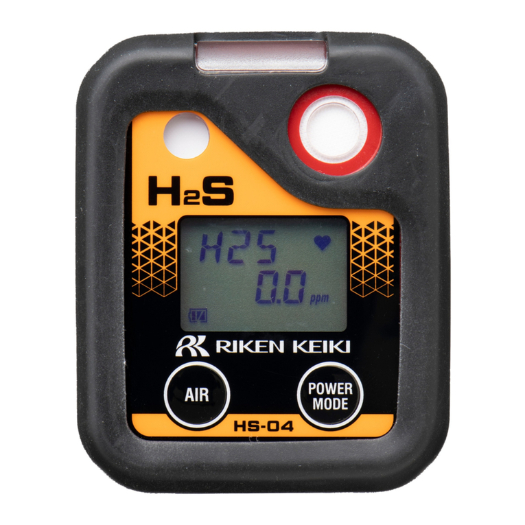
Riken Keiki 04 Series Operation manual

Xtrails
Xtrails VESDA ECO installation instructions

International Gas Detectors
International Gas Detectors POR-MULT user manual
