Proseries 63134 User manual

:
:
63134
Q-Slot 2 Bike Rack
Assembly Instructions:
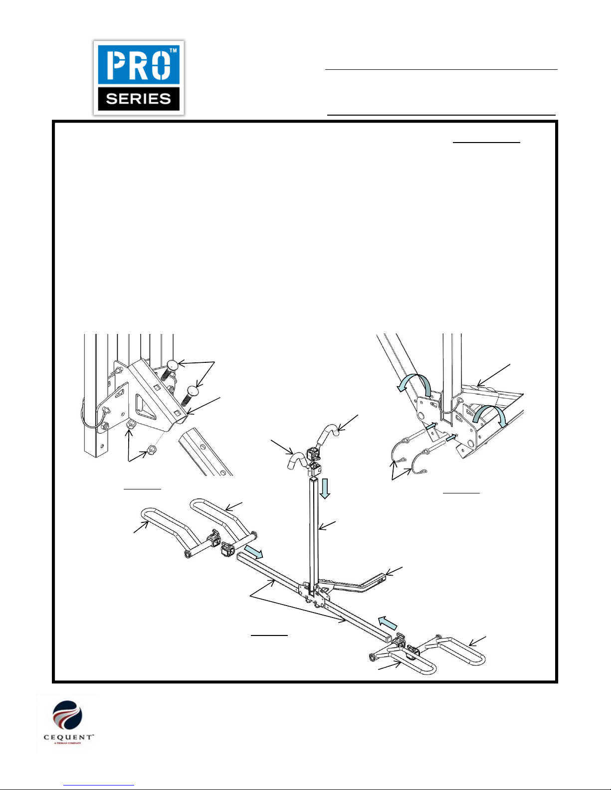
1. Align mounting holes of Receiver Shank with holes in Main Support Assembly. Use the supplied 3/8”
carriage bolts and 3/8” Nylon locking nuts to fasten receiver shank to main support. (Fig 1)
2. Rotate side tubes to the horizontal position as illustrated. Lock side tubes in position with bail pins in
lower position as illustrated. (Fig 2)
3. Slide Wheel Cradle assemblies on side tubes as illustrated. (Fig 3)
4. Slide Frame Hook assemblies on center tube as illustrated. (Fig 3)
Kit Contents:
Main Support Arm Assembly 1 Receiver Adapter 1
LH Wheel Cradle Assembly 2 3/8-16 x 2” Carriage Bolt 2
RH Wheel Cradle Assembly 2 3/8-16 Lock Nut 2
Frame Hook Assembly – Long 1 1/2” Anti-Rattle Pin 1
Frame Hook Assembly – Short 1 Flat Washer ½ 1
Receiver Shank 1 Pin Clip 1
ITEM
DESCRIPTION
Main Support Assembly
3/8” Carriage Bolt Main Support Assembly
TOOLS REQUIRED:
9/16 Wrench
¾ Wrench
Cequent Performance Products
Plymouth, MI 48170
Technical Service: (888) 521-0510 Page 1 of 12
FIGURE 1
3/8” Nylon Lock Nut
Main Support Assembly
Frame Hook - Long
Frame Hook - Short
Bail Pin
LH Wheel Cradle
RH Wheel Cradle
RH Wheel Cradle
LH Wheel Cradle
FIGURE 2
FIGURE 3
Center Tube
Receiver Shank
Side Tube
63134N Rev C 4-10-12
Printed in China

:
:
63134
Q-Slot 2 Bike Rack
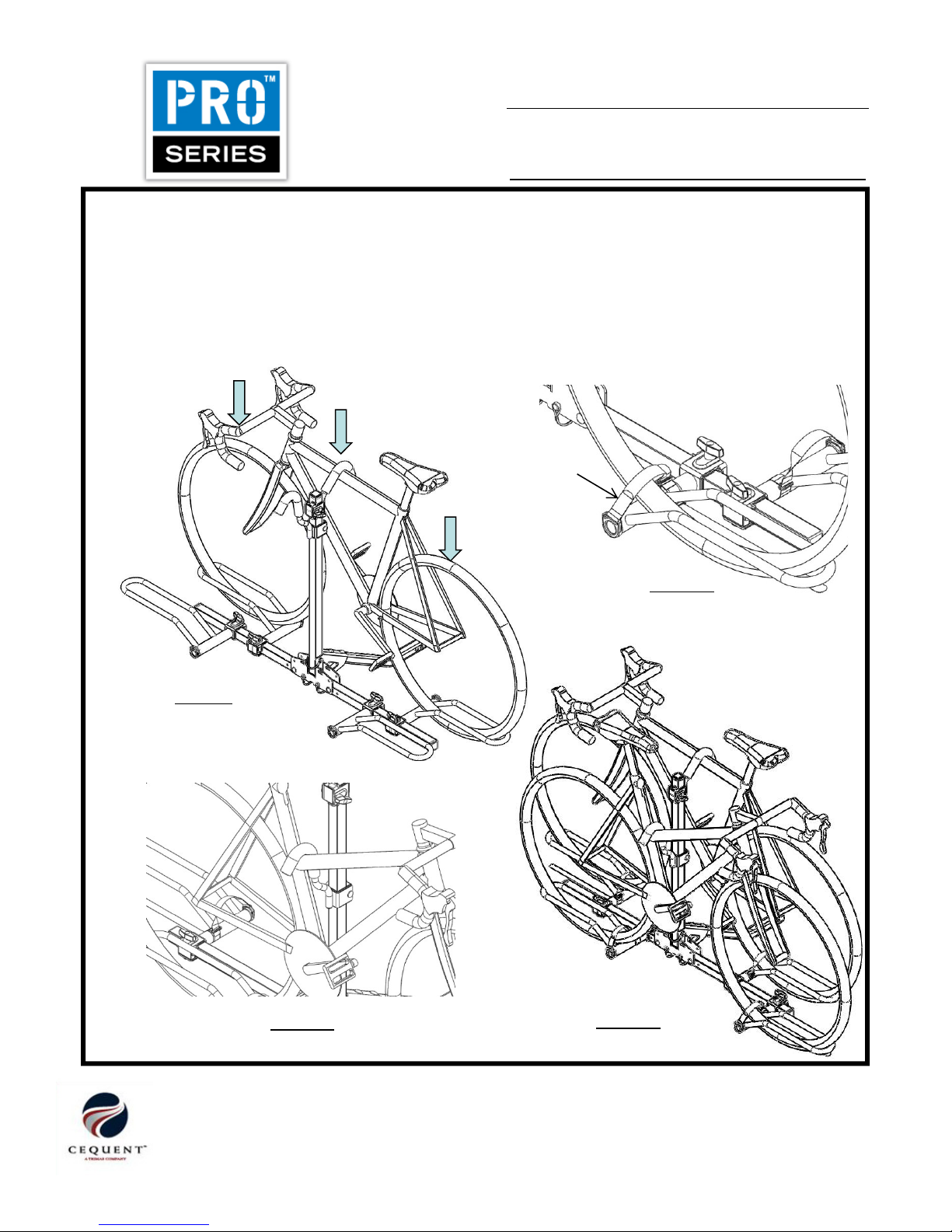
Bicycle Loading:
1. Load inner bicycle first. Pull bail pin and rotate center tube down as illustrated. (Fig 7)
2. Load bicycle into Wheel Cradles. Adjust cradles to appropriate position. Ensure tire is well supported
at both ends of Wheel Cradles. Tighten cradles to prevent movement. (Fig 8)
3. Rotate center tube to vertical position and lock with bail pin. Lower Frame Hook assembly down over
bicycle
frame
as
illustrated
.
(Fig
9
)
FIGURE 4
Install 1/2” Anti-Rattle Pin, Flat Washer and Clip for 1-/4” hitch.
FIGURE 5 & 6
. Install 1/2” Anti-Rattle Pin, Flat Washer, Receiver
Adapter and Clip for 2” hitch.
Receiver Adapter
ITEM
DESCRIPTION
1/2” Flat Washer
1/2” Anti-Rattle Pin
Clip Clip
1/2” Flat Washer
1/2” Anti-Rattle Pin
2” Hitch
1-1/4” Hitch
Cequent Performance Products
Plymouth, MI 48170
Technical Service: (888) 521-0510 Page 2 of 12
bicycle
frame
as
illustrated
.
(Fig
9
)
4. Apply downward pressure to bicycle and Frame Hook assembly. Tighten Frame Hook assembly and
ensure there is no movement of bicycle.
FIGURE 7
FIGURE 8
63134N Rev C 4-10-12
Printed in China
:
:
63134
Q-Slot 2 Bike Rack
CRADLE STRAP
FIGURE 10
Bicycle Loading (continued):
5. Loop Wheel Cradle straps over wheels and secure (Fig 10)
WARNING – Failure to use wheel cradle straps may result in bike falling off rack during use.
6. Load second bicycle as describe in steps 2 thru 5. Reverse direction of second bicycle to prevent
handle bar interference. (Fig 12)
7. Bicycles with inclined frames (angled cross tube i.e. women's bicycles), position frame hook at the
intersection of the vertical tube and inclined tube to prevent slippage during use. (Fig 11)
ITEM
DESCRIPTION
Cequent Performance Products
Plymouth, MI 48170
Technical Service: (888) 521-0510 Page 3 of 12
FIGURE 9
FIGURE 11 FIGURE 12
63134N Rev C 4-10-12
Printed in China

:
:
63134
Q-Slot 2 Bike Rack
IMPORTANT NOTES:
• This bicycle rack has been designed to carry up to two (2)bikes, as long as the maximum weight on the rack
does not exceed 40 kgs or 90 lbs.
• This rack is designed for typical use and applications (on paved or smooth gravel roads). Do not use this rack
on a vehicle that will be driven on rough roads or where the rack (and bikes) will be subjected to significant or
constant jarring and/or shock, or any vehicle with very stiff springs that will transfer the load shocks directly to
the rack and the bikes.
• Always check frame hook, wheel cradle knobs and cradle straps for tightness prior to each trip.
• Replace straps if they appear worn or frayed.
• Proper fitting and installation of this carrier to your specific vehicle is critical, and is the owner’s sole
responsibility.
• Improper use of this product may result in damage to your vehicle, your bicycles, or even other
vehicles driving behind you (as a result of colliding with or trying to avoid fallen bicycles and/or the rack).
• When leaving the bike carrier outside for extended periods of time the finish will lose its luster. It is
recommended that when not in use the rack is stored indoors.
• Take care to add padding on any area of the bikes that touches another bike or any part of the vehicle.
Damage can and will happen (to your bikes and/or to the vehicle) if care is not taken during the loading and
transporting of your bikes, and padding used where necessary.
• Bicycle tires should be kept at least 6” away from the exhaust pipes of the vehicle. The high temperature
exhaust exiting from the exhaust pipes is hot enough to melt or damage tires. Keep all bike tires totally
away from the direct exhaust flow.
•
Bikes fitted with large accessories (such as child carrying seat) will greatly increase the possibility of
ITEM
DESCRIPTION
Cequent Performance Products
Plymouth, MI 48170
Technical Service: (888) 521-0510
•
Bikes fitted with large accessories (such as child carrying seat) will greatly increase the possibility of
interference with mounting to the rack on the vehicle.
• After reading this manual, should you have any additional questions regarding the compatibility, fitting and/or
use of this rack, please call your nearest ProSeries® authorized retail dealer or Cequent Technical Service.
WARNING:
•Improper mounting will void the rack warranty.
•Damage to bicycles or rack due to ground clearance problems are not covered by warranty.
•Not for off road use.
Page 4 of 12
63134N Rev C 4-10-12
Printed in China
:
:
63134
Cargador para 2 bicicletas con ranura Q
Instrucciones de ensamble:
1. Alinee los orificios de montaje del vástago receptor con los orificios en el ensamble de apoyo
principal. Use los pernos de carruaje de 3/8” que se suministran y las tuercas de bloqueo de nylon de
3/8” para sujetar el vástago receptor al soporte principal. (Fig 1)
2. Rote los tubos laterales hacia la posición horizontal como se ilustra. Bloquee los tubos laterales en
su posición con los pasadores de liberación en las posiciones inferiores como se ilustra. (Fig 2)
3. Deslice los ensambles de las bases de las ruedas en los tubos laterales como se ilustra. (Fig 3)
4. Deslice los ensambles del gancho del marco en el tubo central como se ilustra. (Fig 3)
Contenido del Kit:
Ensamble del brazo de apoyo principal 1 Adaptador del receptor 1
Ensamble de la base de rueda izquierda LH 2 Perno de carruaje 3/8-16 x 2” 2
Ensamble de la base de rueda derecha RH 2 Tuerca de bloqueo 3/8-16 2
Ensamble del gancho del marco – Largo 1 Ensamble del gancho del marco – Corto 1
Cheville antibruit 1/2-13 1 Rondelle plate 1/2” 1
Vástago receptor 1 Gancho pasador 1
ARTÍCULO
DESCRIPCIÓN
Ensamble de soporte principal
Perno de carruaje de 3/8” Ensamble de soporte principal
OUTILS REQUIS :
Clé 9/16
Clé 3/4
Cequent Performance Products
47774 Anchor Court
Plymouth, MI 48170
Servicio técnico: (888) 521-0510
63134N Rev C 4-10-12
Impreso en China
Page 5 of 12
FIGURA 1
Tuerca de bloqueo de nylon de 3/8”
Ensamble de soporte principal
Gancho del ,marco - largo
Gancho del marco - corto
Pasador de liberación
Base de la rueda izquierda LH
Base de la rueda derecha RH
Base de la rueda derecha RH
Base de la rueda izquierda LH
FIGURA 2
FIGURA 3
Tubo central
Vástago receptor
Tubo lateral
Table of contents
Languages:
Other Proseries Automobile Accessories manuals


Popular Automobile Accessories manuals by other brands


ULTIMATE SPEED
ULTIMATE SPEED 279746 Assembly and Safety Advice

SSV Works
SSV Works DF-F65 manual

ULTIMATE SPEED
ULTIMATE SPEED CARBON Assembly and Safety Advice

Witter
Witter F174 Fitting instructions

WeatherTech
WeatherTech No-Drill installation instructions

TAUBENREUTHER
TAUBENREUTHER 1-336050 Installation instruction