manuals.online logo
Brands
  1. Home
  2. •
  3. Brands
  4. •
  5. Draper
  6. •
  7. Lifting System
  8. •
  9. Draper Micro projector lift User manual

Draper Micro projector lift User manual

Copyright © 2002 Draper, Inc. Form MicroProjectorLift220V_Inst02 Printed in U.S.A.
Planning
➀Based on screen location and projector specifications, determine proper
position for projector installation.
➁Confirm that there is adequate space for installation and operation.
Minimum clearance above ceiling level varies according to Micro Projector
Lift plus height of projector, optional projector mounting bracket, optional
ceiling closure, and optional plenum rated housing.
➂Arrange to provide service access to the unit.
As Soon As Micro Projector Lift Arrives
➀Open carton and inspect for damage.
➁Locate the following parts:
A. The unit itself
B. Controls
C. Any optional equipment
Installation/Operating Instructions
220 V Micro Projector Lift by Draper
Hanging Unit
The Micro Projector Lift is provided with four (4) holes with
5
/
16
"-18 clinch nuts
provided for suspending or direct mounting the unit. The unit should be guy
wired or blocked to prevent swinging.
All installations should observe the following guidelines:
➀Installer must ensure that all fasteners and supports are of adequate
strength to securely support Micro Projector Lift and projector.
➁Fastening methods must be suitable for mounting surface, and securely
anchored so that vibration or abusive pulling on unit will not weaken
installation.
➂Bottom of unit must be unobstructed after installation. Sufficient clearance
must be allowed below projector or optional ceiling closure.
➃Do not use unit to support adjacent ceiling, light fixtures, etc.
➄Do not complete the ceiling below unit until electrical connections have
been completed and unit has been operated successfully.
➅We recommend that safety cables be attached to the Micro Projector Lift
for added security (a sound installation practice with overhead equipment).
Electrical Connections
Unit operates on 220 V a.c., 50 Hz. current.
The Micro Projector Lift is shipped closed, with a temporary field connection
provided in the form of a pigtail temporarily wired to the unit. After hanging the
unit, make sure power is off and use this pigtail to temporarily connect the unit
to power and to a switch, so the unit can be lowered to allow access inside.
Please note: Make sure electrical supply has been disconnected before
attempting to connect MPL to power.
Terminal strip for field connections is located inside the unit on the left (as
seen from front, or non-scissored end). Unit is shipped with internal wiring
complete to the terminal strip. Once the unit has been lowered, turn off power,
disconnect temporary pigtail from unit, then complete permanent wiring to
electricity and to switches. Wire to connect unit to power supply and to
switches should be furnished by installer. Connections should be made in
accordance with wiring diagram, and wiring should comply with national and
local electrical codes. All operating switches should be “off” before power is
connected.
Micro Projector Lift should be operated and checked prior to installing
projector and/or optional ceiling closure.
Caution:
➀Read instructions completely before proceeding.
➁Follow instructions carefully. Installation contrary to instructions
invalidates warranty.
➂Do not obstruct operation of Micro Projector Lift with fingers or any
object. Serious injury or damage could result.
➃The Micro Projector Lift is designed to accommodate ceiling suspended
equipment. Equipment should not be allowed to rest on ceiling closure
during operation. (Refer to section titled “Installing Projector.”)
➄Entire bottom of unit must be unobstructed to permit proper operation.
➅Unit must be installed level (use a carpenter’s level).
➆Unit operates on 220 V a.c. current.
Note:
Unit has been thoroughly inspected and tested at factory and found
to be operating properly prior to shipment.
Operation
When unit is first operated, be cautious! If unit fails to operate when the switch
is flipped “down”, return switch to “off” and recheck electrical connections
before proceeding. Cycle unit down and up several times to confirm
satisfactory operation.
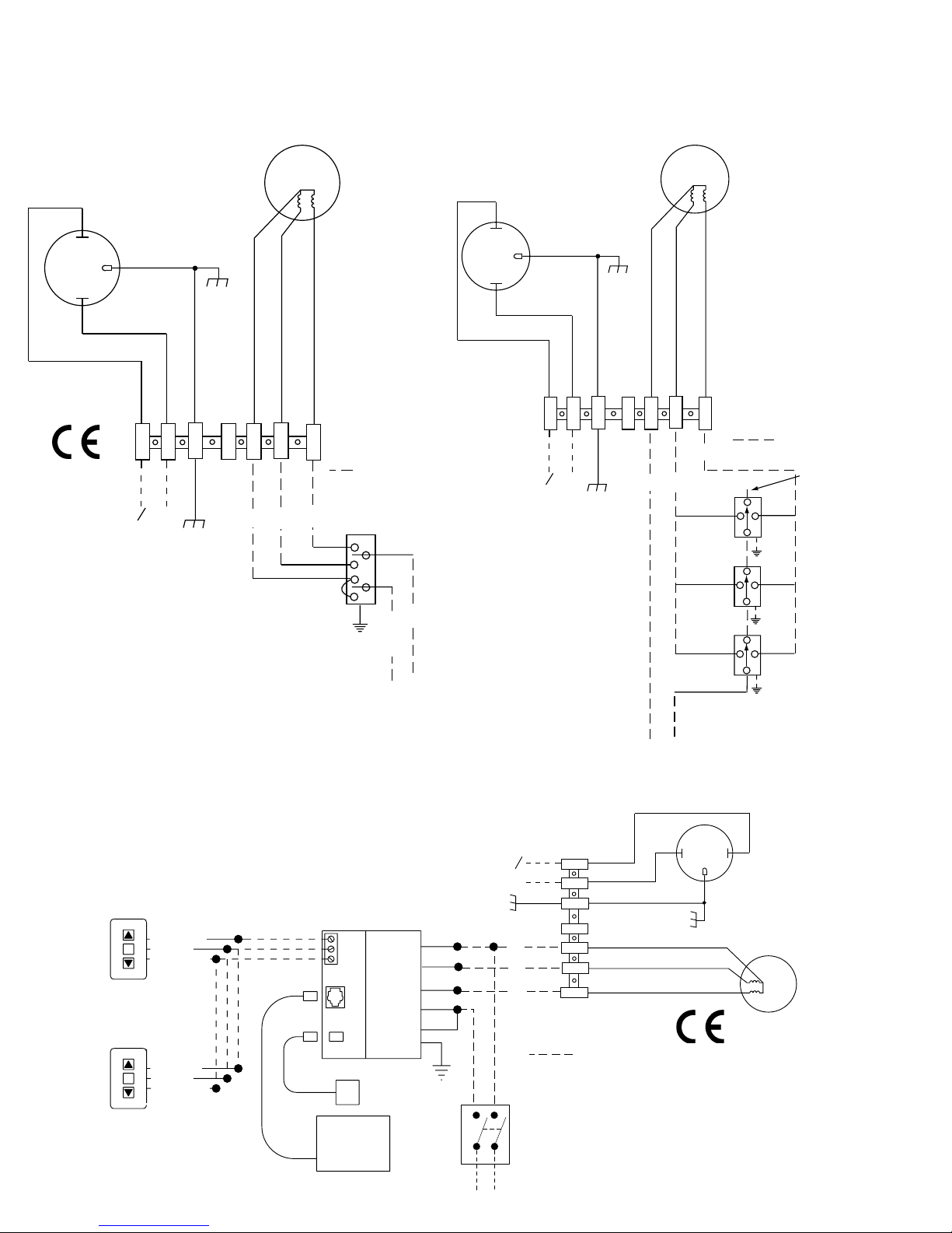
220 V Single Station Control (CE Approved)—3-position UP-OFF-DOWN
switch permits operation to be stopped at any point. Factory set limit
switches automatically stop lift when fully down or fully up.
220 V Multiple Station Control (Not CE Approved)—Switches are similar
in appearance to Single Station Control. Lift stops when switch is released
and may be restarted in either direction. Factory set limit switches stop lift
automatically when fully up or fully down.
24 V Control (CE Approved)—Three-button UP-STOP-DOWN switches
stop at any point desired, operate in any sequence. Factory set limit
switches automatically stop lift when fully up or fully down. Wireless con-
trols—whether infrared or radio frequency—interface with low voltage
control box.
Key Operated Switching (Not CE Approved)—Two kinds of key-operated
switches are optionally available with this unit.
➀The key-operated power supply switch controls power to the lift and
switches. When it is “off”, the switches will not operate lift. Key may be
removed from the switch in “on” or “off” position.
➁A three-position key switch permits the lift to be operated directly by
key. In this case, the lift’s operator must have a key.
These Installation/Operating Instructions are available in the official language
of the country where you purchase the product. Please contact your distributor
to request a copy.
Vous pourriez demander les instructions d’installation et d’opération traduises
dans la langue officielle du pays ou vous achetez le produit. Veuillez
demander à votre distributeur.
Die Gebrauchsanweisung für Installation und Konstruktion sind in der
offiziellen Sprache des Landes, indem Sie das Produkt gekauft haben,
vorhanden. Fragen Sie die jeweilige Verkaufs-Abteilung.
533 mm 528 mm
Min. 127 mm
Max. 1346 mm
Varies with
projector/bracket
and room
conditions
220 V Micro Projector Lift by Draper, Inc. page 2 of 4
Plenum Housing, Lift, and Closure
If you encounter any difficulties installing or servicing your 220 V a.c. Micro
Projector Lift, call your dealer or Draper, Inc. in Spiceland, Indiana, 765-987-
7999, or fax 765-987-7142.
Installing Optional Ceiling Trim Kit
The Micro Projector Lift is available with a ceiling trim kit.
This kit consists of
the lower section of the plenum housing and the optional closure panel.
Please refer to drawings below for these instructions.
➀Install Micro Projector Lift as previously described in these instructions.
➁Install bottom section of plenum housing in opening. This can be
accomplished by suspending with wire, or by mounting directly to the
ceiling joists (if space permits).
➂Install projector and attach optional ceiling closure to Micro Projector Lift
(see instructions on page 3).
Upper Section
MPL
Middle Section
Lower Section
Ceiling tile
Lower section of
Plenum Housing
Installing Optional Plenum Housing
The Plenum Housing is shipped pre-assembled in its shortest position. The
height of the plenum can be adjusted by moving the screws to different
mounting holes in side panels. You can install the plenum housing in a pre-
assembled state or as separate components, which will require that the
plenum housing be completely disassembled prior to installation.
Please Note:
If the plenum is to be installed in a space where there is no access from
above the plenum, then it is recommended that the Micro projector Lift
be installed to the upper section prior to installing the plenum housing.
Please refer to drawing below for these instructions.
➀Install top section of plenum housing using outer four holes located on top
of upper section.
➁Attach Micro Projector Lift to upper section of plenum housing through the
inner four holes in the upper section with the
5
/
16
"–18 x
7
/
8
" hex head
screws,
5
/
16
" flat washers, and lock washers provided with plenum housing.
The lock washers should be used
above
the plenum housing (one per
screw); the flat washers should be used
between
the plenum housing and
the MPL (three flat washers per screw).
➂Attach the two flat panels of the middle section across from each other
with the clinch nuts to the outside of the housing.
➃Attach the two middle section panels with the formed ends across from
one another.
➄Attach lower section of plenum housing.
➅Use 25 mm foil tape (roll provided with plenum housing) to cover any
unused screw holes in plenum housing.
Overall
Height
508 mm Max.
305 mm Min.
Available
Projector/
Bracket
Height
343 mm Max.
140 mm Min.
220 V Micro Projector Lift by Draper, Inc. page 3 of 4
Low Profile Aero Lift Bracket
* Projector-specific bracket height varies according to the
projector model. Contact Draper, Inc. for details.
Installing Projector
Generally, the video projector should be suspended from the bottom pan
according to projector manufacturer’s instructions or using optional Low
Profile Aero Lift Bracket. If the Low Profile Aero Lift Bracket is used, holes are
pre-drilled for attachment.
If for any reason the hole placement must be changed, completely lower
Micro Projector Lift before attempting to drill new holes.
The Micro Projector Lift has a grounded 220 V a.c., 50Hz power cord for
projector power supply. The power cord is laced down the back scissor and is
“hot” at all times. Control cables (maximum of four) should be laced through
our Cable Management System (back scissor only—see method used for
power cord). This will ensure that cords do not become tangled and damaged
during Micro Projector Lift operation.
Unit and projection system should be operated, checked and adjusted as
necessary at this time (see below for limit adjustment procedures).
Warning: Keep fingers & other objects away from ceiling closure & scissor
mechanisms when unit is operating. Serious injury or damage can result.
Installing Ceiling Closure
If your Micro Projector Lift is equipped with a ceiling closure system, it can be
used as is, or in conjunction with a square of existing ceiling tile.
Please refer to diagram at right for these instructions.
➀If installing with ceiling tile, you may need to cut tile so that its overall
dimensions are the same as (or slightly less than) the closure panel. Place
tile into trim frame. Lay closure panel on top (back side) of ceiling tile, and
tighten screws to hold in place.
➁Attach
5
/
16
"-18 threaded rods to pem nuts in lift pan.
➂Run unit “up” until bottom pan stops at highest position. Mark position on
5
/
16
"-18 rods even with ceiling level and cut rods to length (removing
from pan if convenient).
➃Run unit “down” until bottom pan stops at “show” position.
➄Attach closure to lower end of
5
/
16
"-18 rods by slipping into four corner
slots and secure with nuts above and below slots.
➅Run unit “up” again to highest position. Measure distance by which panel
fails to reach required “closed” height for surrounding ceiling.
➆Run unit “down” then readjust mounting of
5
/
16
"-18 rods in traveling grid
to raise panel required distance.
➇Test unit operation to confirm that panel will stop in closed position just
before touching ceiling.
NOTE: Immediately upon completion of the surrounding ceiling, units should
be operated to confirm that optional ceiling closure panel stops just short of
touching ceiling in closed position.
Adjustments
CAUTION: Be sure all switches are in “off” position before adjusting limit
switches. Always be prepared to shut lift off manually when new adjustment is
being tested.
Please refer to diagram at right for these instructions.
Limit switches for the Micro Projector Lift are preset at the factory. The “Up”
(closed) limit switch is set for fully closed. The “down” limit switch is set for
fully lowered (1219 mm). Once unit is in place, the “down” limit switch may
need to be changed to stop the Micro Projector Lift closer to the ceiling (that
is, to raise the “down” position). Limit switches are located on the left end of
roller (as seen from the front, or non-scissored end, of the unit) and are
accessible to a screwdriver/Allen wrench (
5
/
32
").
Adjusting Down Position —
“Down” position may be adjusted by turning
limit switch adjustment socket number 1. Turning the socket clockwise will
stop the Micro Projector Lift closer to the ceiling. Turning it counter-clockwise
will cause the lift to stop at a lower point.
Adjusting Up (closed) Position —
Because the “up” (closed) position is
preset at the factory, Draper does not recommend changing this position
using the limit switch. The “up” position of the closure may be changed by
changing the length of threaded rod (see instructions for closure installation
below). If necessary, however, “up” position may be adjusted by turning limit
switch adjustment socket number 2. Turning the socket counterclockwise
creates a higher, or more fully closed position. Turning it clockwise creates a
lower ‘UP” (closed) position.
Caution: Do not set limit switch so that the MPL motor is still running
after the lift is closed. This could result in damage to the motor.
Terminal
Strip
Up (closed)
Limit Switch
Down (open)
Limit Switch
Rear
Scissor Left
Scissor
1
2
+
-
+
-
81 mm
*
Motor
Black (Down)
Dashed wiring
by electrician
Control
switch
N
O
To 220v
50 Hz. Line
Blue (Common)
Brown (Up)
Green (Ground)
White
Black
NDNUP
Neutral
L1
220 V Micro Projector Lift by Draper, Inc. page 4 of 4
Wiring Diagrams
Single Station Control
(CE Approved)
Low Voltage (& Wireless) Control
(CE Approved)
Multiple Station Control
(Not CE Approved)
Motor
Black (Down)
Dashed wiring
by electrician
Blue
Black
Red
N
O
To 220v 50 Hz. Line
Blue (Common)
Brown (Up)
Green (Ground)
White
Black
NDN
UP
Blue
Red
Blue
Red
Black
Black
Cap off with
wire nut
and tape
Neutral
Hot
Motor
Black (Down)
Dashed wiring
by electrician
N
O
To 220v
Line
Blue (Common)
Brown (Up)
Green (Ground)
White
Black
N
DN
UP
STOP
Control
Switches
24v DC
Black (DN)
Red (UP)
White (COM)
Black (DN)
Red (UP)
White (COM)
STOP
Black
Red
White
White
Brown
Red
Black
Yellow
Green
Low Voltage Control Module
Optional Infrared
Receiver Package
Optional
Radio
Receiver
Package
220v, 50 Hz.
All-Pole Disconnect
by Others

Other Draper Lifting System manuals

Draper AeroLift 100 220V Installation instructions

Draper

Draper AeroLift 100 220V Installation instructions

Draper AeroLift 25 Manual

Draper

Draper AeroLift 25 Manual

Draper 56177 User manual

Draper

Draper 56177 User manual

Draper 78610 User manual

Draper

Draper 78610 User manual

Draper AeroLift 25 Manual

Draper

Draper AeroLift 25 Manual

Draper AeroLift 35 Manual

Draper

Draper AeroLift 35 Manual

Draper Flatscreen Lift FSL-F-42 Manual

Draper

Draper Flatscreen Lift FSL-F-42 Manual

Draper 37777 User manual

Draper

Draper 37777 User manual

Draper SLX17 Operating instructions

Draper

Draper SLX17 Operating instructions

Draper AeroLift 50 Manual

Draper

Draper AeroLift 50 Manual

Draper AeroLift 50 Manual

Draper

Draper AeroLift 50 Manual

Draper AeroLift 150 Manual

Draper

Draper AeroLift 150 Manual

Popular Lifting System manuals by other brands

HWH 200 series Operator's manual

HWH

HWH 200 series Operator's manual

Noblelift CG1646 Service maintenance manual

Noblelift

Noblelift CG1646 Service maintenance manual

Remaco PLT-412 installation guide

Remaco

Remaco PLT-412 installation guide

Aqua Creek Scout 2 user manual

Aqua Creek

Aqua Creek Scout 2 user manual

Challenger Lifts CL12A Installation, operation & maintenance manual

Challenger Lifts

Challenger Lifts CL12A Installation, operation & maintenance manual

probst WEZ-2 operating instructions

probst

probst WEZ-2 operating instructions

Upright AB38 Operation and parts manual

Upright

Upright AB38 Operation and parts manual

JLG 400S Operation manual

JLG

JLG 400S Operation manual

Sunex Tools 4412 owner's manual

Sunex Tools

Sunex Tools 4412 owner's manual

Garaventa Xpress II owner's manual

Garaventa

Garaventa Xpress II owner's manual

Space SDH 370.55 LIKT manual

Space

Space SDH 370.55 LIKT manual

morse 525-N-125 Operator's manual

morse

morse 525-N-125 Operator's manual

AFF 3182 owner's manual

AFF

AFF 3182 owner's manual

Omer Tripark 25 installation manual

Omer

Omer Tripark 25 installation manual

Freedom Lift Systems Trus-T-Lift 750 Installation and operation manual

Freedom Lift Systems

Freedom Lift Systems Trus-T-Lift 750 Installation and operation manual

Nexus 21 L-85 installation manual

Nexus 21

Nexus 21 L-85 installation manual

JLG 340AJ Operation and safety manual

JLG

JLG 340AJ Operation and safety manual

Lukas LX LIFT operating instructions

Lukas

Lukas LX LIFT operating instructions

manuals.online logo
manuals.online logoBrands
  • About & Mission
  • Contact us
  • Privacy Policy
  • Terms and Conditions

Copyright 2025 Manuals.Online. All Rights Reserved.