ProSoft PCL-841 User manual

PCL-841
Dual-Port CAN
Interface Card

Copyright
This documentation is copyrighted 1996 by Advantech Co., Ltd. All
rights are reserved. Advantech Co., Ltd. reserves the right to make
improvements in the products described in this manual at any time
without notice.
No part of this manual may be reproduced, copied, translated or
transmitted in any form or by any means without the prior written
permission of Advantech Co., Ltd. Information provided in this
manual is intended to be accurate and reliable. However, Advantech
Co., Ltd. assumes no responsibility for its use, nor for any infringe-
ments of the rights of third parties which may result from its use.
Acknowledgments
PC-LabCard is a trademark of Advantech Co., Ltd. IBM and PC are
trademarks of International Business Machines Corporation. All
brand and product names appearing in this document are registered
trade marks or trademarks of their respective holders.
Part No. 2000841000 1st Edition
Printed in Taiwan May 1996

Contents
Chapter 1
Introduction........................................................................... 1
Introduction....................................................................................2
Features ..........................................................................................3
Specifications.................................................................................3
Chapter 2
HardwareInstallation........................................................... 5
Initial inspection ............................................................................6
Jumper and switch locations ..........................................................7
Card configuration.........................................................................8
Chapter 3
SoftwareProgramming....................................................... 13
Library functions .........................................................................14
Example program.........................................................................19
Chapter 4
DataMonitor Utility ............................................................ 21
Software overview........................................................................22
Main Menu...................................................................................22
Chapter 5
Wiring .................................................................................. 27
Pin assignments............................................................................28
CAN signal wiring .......................................................................29
Appendix A
Register Structure ............................................................... 31
CAN controller address allocation...............................................32
Register address map ...................................................................33
Register descriptions....................................................................34

Chapter 1 General Information 1
1
Introduction
CHAPTER

2PCL-841 User's Manual
Introduction
The PCL-841 is a special purpose communication card that brings the
Control Area Network to your PC. With the built-in CAN controller,
the PCL-841 provides bus arbitration and error detection with
automatic transmission repeat function. This drastically avoids data
loss and ensures system reliability. The on-board CAN controllers are
located at different positions in the memory. You can run both CAN
controllers at the same time, independently. The PCL-841 operates at
baud rates up to 1 Mbps and can be installed directly into the expan-
sion slot of your PC.
Control Area Network
The CAN (Control Area Network) is a serial bus system especially
suited for networking "intelligent" I/O devices as well as sensors and
actuators within a machine or plant. Characterized by its multi-master
protocol, real-time capability, error correction, high noise immunity,
and the existence of many different silicon components, the CAN
serial bus system, originally developed by Bosch for use in automo-
biles, is increasingly being used in industrial automation.
Direct memory mapping
The PCL-841 is assigned with memory address, which allows direct
access to the CAN controller. This is the simplest and fastest way of
programming any board in a PC because the board is regarded as
standard RAM.
Optical Isolation Protection
On-board optical isolators protect your PC and equipment against
damage from ground loops, increasing system reliability in harsh
environments.

Chapter 1 General Information 3
Features
• Operates two separate CAN networks at the same time
• High speed transmission up to 1 Mbps
• 16 MHz CAN controller frequency
• Takes a 4 KB address space, 40 base address adjustable in steps
from C800H up to EF00H
• Optical isolation protection of 1000 VDC ensures system reliability
• Wide IRQ selection for each port includes:
IRQ 3, 4, 5, 6,7, 9, 10, 11, 12, 15
• LED indicates Transmit/Receive status on each port
• Direct memory mapping enables speedy access to the CAN
controllers
• C library and examples included
Specifications
•Ports: 2
•CAN controller: 82C200
•CAN transceiver: 82C250
•Signal support: CAN-L, CAN-H
•Memory address: From C800H to EF00H
•IRQ: 3, 4, 5, 6, 7, 9, 10, 11, 12, 15
•Isolation voltage: 1000 VDC
•Power consumption: +5 V @ 400 mA typical, 950 mA max.
•Connectors: Dual DB-9 male connectors
•Operating temperature: 32 to 122oF (0 to 50oC)
•Dimensions: 7.25" x 4.13" (18.4 x 10.5 cm)
•Shipping weight: 0.9 lb (0.4 kg)

4PCL-841 User's Manual

Chapter 2 Hardware Installation 5
2
Hardware
Installation
CHAPTER

6PCL-841 User's Manual
Initial inspection
You should find the following items inside the shipping package (in
addition to this manual):
• PCL-841 Dual-port CAN Interface Card
• C Driver and DataMonitor Utility Diskette
We have carefully inspected the PCL-841 mechanically and electrical-
ly before shipping. It should be free of marks and scratches and in
perfect working order upon receipt.
As you unpack the PCL-841, check it for signs of shipping damage
(damaged box, scratches, dents, etc.). If it is damaged or it fails to
meet specifications, notify our service department or your local
representative immediately. Also notify the carrier. Retain the shipping
carton and packing material for inspection by the carrier. After
inspection we will make arrangements to repair or replace the unit.
When you handle the PCL-841, remove it from its protective packag-
ing by grasping the rear metal panel. Keep the anti-vibration packing.
Whenever you remove the card from the PC, store it in this package
for protection.
Warning! Modern electronic devices are very sensitive to
damage from static electricity.Ground yourself
before you touch the card.We recommend that you
use a grounded wrist strap and place the card on a
static dissipative mat whenever you work with it. At
the very least, touch the back of the grounded
chassis of the system unit (metal) before you handle
the board. Avoid contact with materials that hold a
static charge, such as styrofoam. Do not touch the
exposed circuit connectors.
Chapter 2 Hardware Installation 7
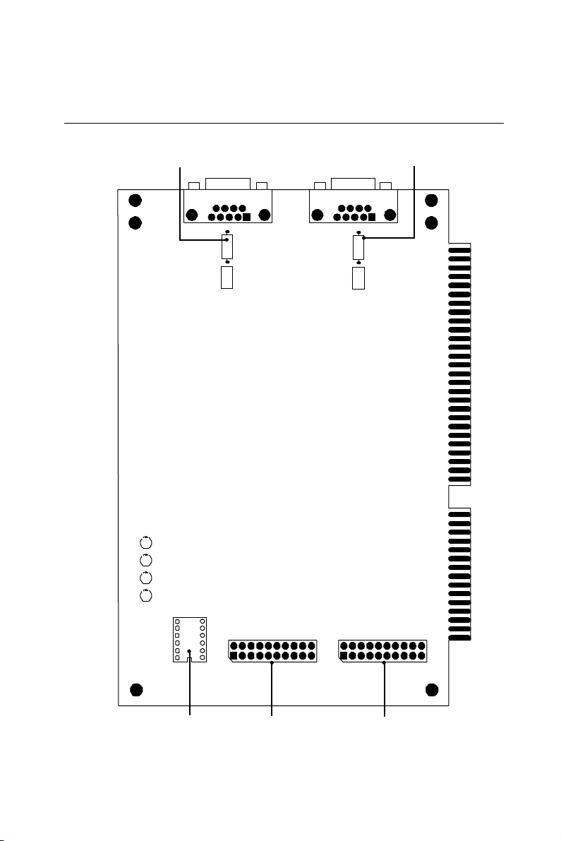
JP1
DIPSW
JP2
P2
P1
PCL-841 REV. A1 ISOLATED CAN COMMUNICATION CARD
A17
A1
5
A14
A1
3
A12
A1
6
D1
D2
D3
D4
TR2
JP10
TR1
JP9
Port 1 Termination Resistor Port 2 Termination Resistor
Jumper and switch locations
Port 2 IRQ Select
Port 1 IRQ Select
Ports 1 and 2 Memory
Base Address

8PCL-841 User's Manual
Card configuration
The PCL-841 has two ports, each with one jumper. The jumpers set
the IRQ for the ports, which can be configured separately. A DIP
switch sets the memory base address for each port. The following
chart shows the function of the jumper and the switch (see the
previous page for jumper and switch locations).
Switch and jumper functions
CAN controllers
JP1 Port 1
JP2 Port 2
Memory base address
S W 1 Port 1, Port 2
Default settings
Port 1 is set for COM1 (IRQ=12, Memory address=DA00:0000).
Port 2 is set for COM2 (IRQ=15, Memory address=DA00:0200).
If you need to change these settings, see the following sections.
Otherwise, you can simply install the card. Note that you will need to
disable your CPU card's on-board COM ports, if any, or set them to
alternate addresses/IRQs.
Chapter 2 Hardware Installation 9
3
4
5
6
7
9
10
11
12
15
¡¡
¡¡
¡¡
¡¡
¡¡
¡¡
¡¡
¡¡
¡¡
¡¡
IRQ Ch.2
3
4
5
6
7
9
10
11
12
15
IRQ Ch.1
¡¡
¡¡
¡¡
¡¡
¡¡
¡¡
¡¡
¡¡
¡¡
¡¡
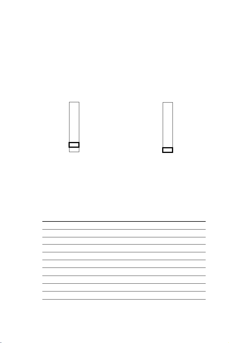
Interrupt (IRQ) setup (JP1 and JP2)
Jumpers JP1 and JP2 set the interrupts for Port 1 and Port 2, respec-
tively. You can choose any IRQ from 3 to 15, except 8, 13 and 14.
When you choose IRQs, make sure they are not used for other cards in
the system. The following figures show the card's default settings.
JP1: Port 1 IRQ Default JP2: Port 2 IRQ Default
Memory base address (SW1)
The memory base address for the PCL-841, which requires 4 KB of
address space, is made up of the memory segment and its associated
offset. The address for the memory segment is set through SW1, a six-
position DIP switch. You can choose any base address from C800 to
EF00. The following table shows the DIP switch settings and the
corresponding base addresses.
Memory address configuration (SW1)
Address/DIP switch A12 A13 A14 A15 A16 A17
C800H on on on off on on
C900H off on on off on on
CA00H on off on off on on
CB00H off off on off on on
CC00H o n on off off on on
CD00H off on off off on on
CE00H on off off off on on
CF00H off off off off o n o n

10 PCL-841 User's Manual
Memory address configuration (SW1) cont'd
Address/DIP switch A12 A13 A14 A15 A16 A17
D000H on on on on off on
D100H off on on on off on
D200H on off on on off on
D300H off off on on off on
D400H on on off on off on
D500H off on off on off on
D600H on off off on off on
D700H off off off on off on
D800H on on on off off on
D900H off on on off off on
DA00H on off on off off on
DB00H off off on off off on
DC00H on on off off off on
DD00H off on off off off on
DE00H on off off off off on
DF00H off off off off off on
E000H on on on on on off
E100H off on on o n on off
E200H on off on on on off
E300H off off on on on off
E400H on on off on on off
E500H off on off on on off
E600H on off off on on off
E700H off off off on on off
E800H on on on off on off
E900H off on on off on off
EA00H on off on off on off
EB00H off off on off on off
EC00H on on off off on off
ED00H off on off off on off
EE00H on off off off on off
EF00H off off off off on off

Chapter 2 Hardware Installation 11
Memory area
Once the memory segment for the base address is selected, the offset
will be automatically assigned for Port 1, Port 2, and hardware reset.
The following table shows the base addresses of the CAN controllers.
Base address (hex) CAN controller
base:0000h - base:00FFh Basic- Port 1
base:0100h - base:01FFh HW reset Basic - Port 1
base:0200h - base:02FFh Basic- Port 2
base:0300h - base:03FFh HW reset Basic - Port 2
base:0400h - base:0FFFh Not used

12 PCL-841 User's Manual

Chapter 3 Software Programming 13
3
Software
Programming
CHAPTER

14 PCL-841 User's Manual
Library functions
Quick reference table
The following table lists the available functions and their correspond-
ing syntax and descriptions.
Library functions
Function Syntax (in C) Description
1 canInitHW() Sets IRQs
2 canExitHW() Releases settings
3 canReset() Resets CAN port
4 canConfig() Controls CAN port settings
5 canNormalRun() Sets mode
6 canSendMsg() Sends message
7 canReceiveMsg() Reads data
Complete function description
Function 1
Sets an IRQ number for Port1 and Port 2.
❒Command canInitHW (UI segment, BYTE IRQ1, BYTE
IRQ2)
❒Argument UI segment, BYTE IRQ1, BYTE IRQ2
segment=c000-df00 step 0x100
IRQ1=Port 1 IRQ number 0 (polling),
3, 4, 5, 6, 7, 8, 9, 10, 11, 12, 14, 15
IRQ2=Port 2 IRQ number 0 (polling),
3, 4, 5, 6, 7, 8, 9, 10, 11, 12, 14, 15
0: polling
❒Response 1=successful

Chapter 3 Software Programming 15
0=fail
❒Example
#include "can841.h"
main()
{UI gSegment=0xDA00;
BYTE CAN1_IRQ, CAN2_IRQ;
CAN1_IRQ=12;
CAN2_IRQ=15;
if (canInitHW (gSegment, CAN1_IRQ, CAN2_IRQ)==0)
printf ("HARDWARE INITIALIZATION ERROR!\n");
}
Function 2
Releases all settings of the CAN card.
❒Command canExitHW()
❒Argument None
❒Response 1=successful
0=fail
❒Example
#include "can841.h"
main()
{if (canExitHW()==0)
printf ("CAN RELEASE FAIL!\n");
}
Function 3
Resets CAN port and flushes the TX/RX buffers.
❒Command int canReset (BYTE port);
❒Argument BYTE port;
port= port number (0 or 1)
❒Response 1=successful
0=fail

16 PCL-841 User's Manual
❒Example
#include "can841.h"
main()
{if (canReset (0)==0)
printf ("RESET PORT 1 FAIL!\n");
}
Function 4
Controls the setting of the CAN port's acceptance code, acceptance
mask, and bus timing register.
❒Command canConfig (BYTE port, CAN_STRUCT can);
❒Argument BYTE port, CAN_STRUCT can;
port= port number (0 or 1)
can= CAN struct pointer
❒Response 1=successful
0=fail
❒Example
#include "can841.h"
main()
{CAN_STRUCT can1, can2;
can1.acc_code=0;
can1.acc_mask=0xff;
can1.bt0=0;
can1.bt1=0x1c;
if (canConfig(0,can1)==0)
printf ("CAN PORT 1 CONFIGURE ERROR!\n");
}
Function 5
Sets a CAN port to normal mode for normal operation.
❒Command canNormalRun (BYTE port);
❒Argument BYTE port;
port= port number (0 or 1)

Chapter 3 Software Programming 17
❒Response 1=successful
0=fail
❒Example
#include "can841.h"
main()
{if (canNormalRun(0)==0)
printf ("CAN Port 1 can't change to Normal Mode!\n");
}
Function 6
Tells the CAN port to send a message.
❒Command canSendMsg (BYTE port, MSG_STRUCT
send_msg);
❒Argument BYTE port, MSG_STRUCT send_msg;
port= port number (0 or 1)
send_msg= send buffer pointer
❒Response 1=successful
0=fail
❒Example
#include "can841.h"
main()
{MSG_STRUCT smsg1;
UI i;
smsg1.id=0x015;
smsg1.rtr=0;
smsg1.dlen=8;
for(i=0; i<smsg1.dlen; i++)
smsg1.data[i]=i;
if (canSendMsg(0,smsg1)==1)
printf ("TRANSMISSION SUCCESSFUL!\n");
}
Table of contents
Other ProSoft Recording Equipment manuals


