E2S D2xB1LD2 User manual

European Safety
Systems Ltd.
Impress House, Mansell Road, Acton, London W3 7QH
www.e2s.com
Tel: +44 (0)208 743 8880
Document No. D211-00-401-IS
Issue 1
20-08-22
Sheet 1 of 7
INSTRUCTION MANUAL
D2xB1LD2 LED Beacons
For use in Hazardous Locations
D2XB1LD2
D2XB1LD2-H
1) Product Table
2) Warnings
DO NOT OPEN WHEN AN EXPLOSIVE
ATMOSPHERE IS PRESENT
DO NOT OPEN WHEN ENERGISED
POTENTIAL ELECTROSTATIC CHARGING
HAZARD - CLEAN ONLY WITH A DAMP
CLOTH
Avertissement:
NE PAS OUVRIR UN PRESENCE
D’ATMOSPHERE EXPLOSIVE
NE PAS OUVRIR ENERGIE
DANGER POTENTIEL CHARGE
ÉLECTROSTATIQUE - NETTOYER
UNIQUEMENT AVEC UN CHIFFON HUMIDE
3) Rating & Marking Information
3.1. Fire Alarm Ratings
All models are approved for use as Visual Appliance for use
in Fire Alarm Systems – Private Mode and General Signalling
UL1638A.
The D2xB1LD2DC024 Product Version H (D2xB1LD2-H) is
certified for use as a public mode visual alarm device in
accordance with UL1971 Third Edition and UL1638 Fifth
Edition / CAN/ULC-S526 Fourth Edition. For use in public
mode the beacon must be without the wire guard or plastic
lens cover.
See fire instruction manual D211-00-401-IS-SC-UL
3.2. ATEX / IECEx / UKEx Ratings
Standards
EN IEC 60079-0:2018 / IEC60079-0:2017 (Ed 7):
Explosive Atmospheres - Equipment. General Requirements
EN IEC 60079-7:2015 +A1:2018 / IEC 60079-7:2018 (Ed. 5.1):
Explosive Atmospheres - Equipment Protection by Increased
Safety "e"
EN 60079-31:2014 / IEC 60079-31:2013 (Ed 2):
Explosive Atmospheres - Equipment Dust Ignition Protection by
Enclosure "t"
Ratings
D2xB1LD2: Ex ec IIC T4 Gc Ta -40°C to +50°C
Ex tc IIIC T75°C Dc Ta -40°C to +50°C
Certificate No. DEMKO 14 ATEX 4786493904X
IECEx ULD 14.0004X
UL21UKEX2131X
ATEX Mark, Equipment
Group and Category:
II 3G
II 3D
CE Marking
UKCA Marking
Model Nom. Voltage Voltage Range Max Operating
Current
*
D2xB1LD2DC024 24Vdc 18-54Vdc 346mA
D2xB1LD2DC024 -H
#
24vdc 16-33Vdc (Regulated) 346mA
D2xB1LD2AC115 115Vdc 115-120Vac 50/60Hz 102.4mA
D2xB1LD2AC230 230Vdc 220-230Vac 50/60Hz 75mA
*Max. rms current at worst-case voltage in voltage range.
#D2xB1LD2-H public mode beacon (Product Version H). See Section 3.1
For detailed current ratings of the device please see Section 15.
Table 1: Electrical Ratings.

European Safety
Systems Ltd.
Impress House, Mansell Road, Acton, London W3 7QH
www.e2s.com
Tel: +44 (0)208 743 8880
Document No. D211-00-401-IS
Issue 1
20-08-22
Sheet 2 of 7
3.3. NEC & CEC Ratings
NEC & CEC Class / Division Ratings for US / Canada
Standards
UL 121201-2021 (Ed. 9)
CAN/CSA C22.2 No. 213-17 (Ed. 3)
Ratings
D2xB1LD2:
Class I Div 2 ABCD T4 Ta -40°C to +50°C
Class I Div 2 ABCD T4A Ta -40°C to +40°C
Class II Div 2 FG T6 Ta -40°C to +50°C
Class III Div 1&2 Ta -40°C to +50°C
Installation must be carried out in compliance with the National
Electric Code / Canadian Electric Code
NEC Class / Zone ratings US
Standards
UL 60079-0 (Ed. 7):
Explosive Atmospheres - part 0: Equipment - General
Requirements
UL 60079-7 (Ed. 5):
Explosive Atmospheres - Equipment Protection by Increased
Safety "e"
UL 60079-31 (Ed. 2)
Explosive Atmospheres - Equipment Dust Ignition Protection by
Enclosure "t"
Ratings
D2xB1LD2:
Class I Zone 2 AEx ec IIC Gc T4 Ta -40°C to
+50°C
AEx tc IIIC T75°C Dc Ta -40°C to +50°C
Installation must be carried out in compliance with the National
Electric Code.
CEC Class / Zone ratings Canada
Standards
CAN/CSA C22.2 No. 60079-0 (Ed. 4) 02/2019
Explosive Atmospheres - Part 0: Equipment - General
Requirements
CAN/CSA C22.2 No. 60079-7 (Ed. 2)
Explosive Atmospheres - Equipment Protection by Increased
Safety "e"
CAN/CSA C22.2 No. 60079-31 (Ed. 2)
Explosive Atmospheres - Equipment Dust Ignition Protection by
Enclosure "t"
Rating
D2xB2LD2:
Ex ec IIC Gc X T4 Ta -40°C to +50°C
Ex tc IIIC T75°C Dc X Ta -20°C to +50°C
Installation must be carried out in compliance with the Canadian
Electric Code
4) Zones, Gas Group, Category and
Temperature Classification
When connected to an approved system the D2XB1LD2 LED
beacon may be installed in:
Area Classification
Zone 2
Explosive gas air mixture not likely to occur in
normal operation, and if it does, it will only
exist for a short time.
Zone 22
Explosive dust air mixture not likely to occur in
normal operation, and if it does, it will only
exist for a short time.
Gas Groupings
Group IIA Propane
Group IIB Ethylene
Group IIC Hydrogen and Acetylene
Temperature Classification for Gas Applications
T1 450ºC
T2 300ºC
T3 200ºC
T4 135°C
Dust Groupings
(ATEX / IECEx
/ UKEX
only)
Group IIIA Combustible Flyings
Group IIIB Non-conductive Dust
Group IIIC Conductive Dust
Maximum Surface Temperature for Dust Applications
(ATEX / IECEx
/ UKEX
only)
D2xB1LD2: 75°C
Equipment Category
3G / 3D
Equipment Level Protection
Gc, Dc
Ambient Temperature Range
-40°C to +50°C
IP Rating
IP6X to
EN/IEC60079
-
0
IP66 to EN60529
To maintain the ingress protection rating, the two off cable entries
must be fitted with suitably rated, certified cable entry and/or
blanking devices during installation.
Type Rating
Per UL50E / NEMA250: 4 / 4X / 3R / 13
Installation must be carried out in compliance with the
latest issue of the following standards:
EN60079-14 / IEC60079-14: Explosive atmospheres -
Electrical installations design, selection and erection
EN60079-10-1 / IEC60079-10-1: Explosive atmospheres -
Classification of areas. Explosive gas atmospheres
EN60079-10-2 / IEC60079-10-2: Explosive atmospheres –
Classification of areas. Explosive dust atmospheres

European Safety
Systems Ltd.
Impress House, Mansell Road, Acton, London W3 7QH
www.e2s.com
Tel: +44 (0)208 743 8880
Document No. D211-00-401-IS
Issue 1
20-08-22
Sheet 3 of 7
116,0mm [4,52in.]
116,0mm [4,52in.]
179,2mm [6,99in.]
130,1mm [5,07in.]
132,4mm [5,17in.]
Ø6,92mm [Ø0,270in.] 3/4" NPT
(For pole mount)
M4 X 12mm
Countersunk screw,
customer to fix
116,0mm [4,52in.]
116,0mm [4,52in.]
168,0mm [6,55in.]
130,1mm [5,07in.]
132,4mm [5,17in.]
Ø6,92mm [Ø0,270in.]
3/4" NPT
(For pole mount)
M4 X 12mm
Countersunk screw,
customer to fix
5) Special Conditions of Use
Special Condition for safe Use as stated on the Type
Examination Certificate DEMKO 14 ATEX 4786493904X /
CoC IECEx ULD 14.0004X / UL21UKEX2131X:
When used for a Group III application, the surface of the
enclosure may store electrostatic charge and become a
source of ignition in applications with a low relative humidity
<~30% relative humidity where the surface is relatively free of
surface contamination such as dirt, dust, or oil.
Guidance on protection against the risk of ignition due to
electrostatic discharge can be found in EN TR50404 and IEC
TR60079-32.
End user shall adhere to the manufacturer’s installation and
instruction when performing housekeeping to avoid the
potential for hazardous electrostatic charges during cleaning,
by using a damp cloth.
To maintain the ingress protection rating and mode of
protection, the cable entries must be fitted with suitably rated,
certified cable entry and/or blanking devices during
installation.
The equipment shall only be used in an area of at least
pollution degree 2, as defined in IEC 60664-1.
6) Product Mounting and Access
6.1. Location and Mounting
The location of the beacon should be made with due regard
to the area over which the warning signal must be visible. It
should only be fixed to services that can carry the weight of
the unit.
The D2x beacon should be secured to any flat surface using
the two 7mm fixing holes in the feet of the base. The 2-off
mounting feet supplied with the unit must first be fitted to the
base using the 2-off M4 X 12mm countersunk screws
provided. Additional feet are available as spare parts if
required. The unit can also be pole mounted using the ¾”
NPT Entry in the centre of the base. See Fig. 1a/1b.
Fig. 1a Fixing Location for General Signaling or Private Mode
Fig. 1b Fixing Location for Public Mode
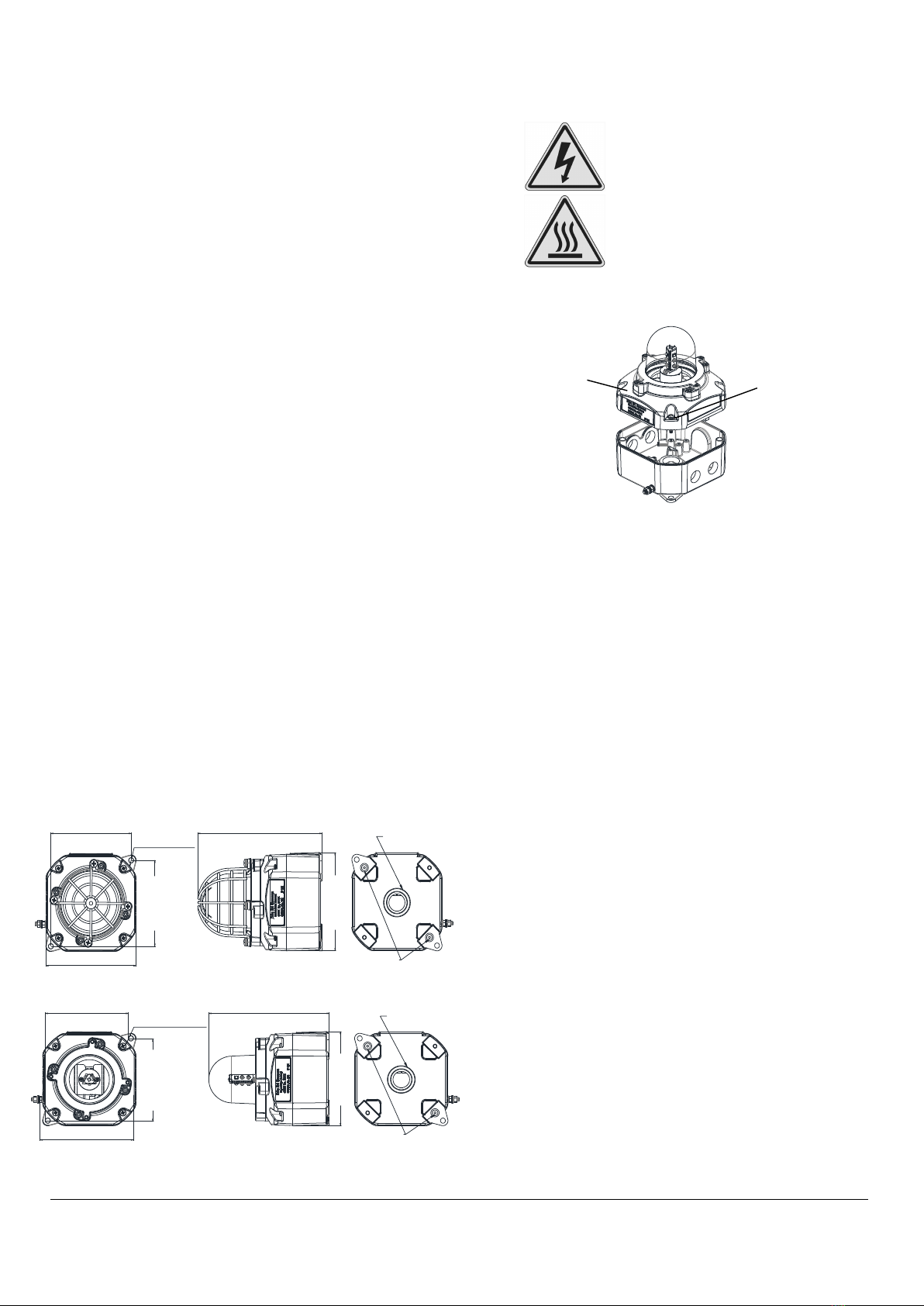
6.2. Access to the Enclosure
Warning – High voltage may be
present, risk of electric shock.
DO NOT open when energised,
disconnect power before opening.
Warning – Hot surfaces. External
surfaces and internal components
may be hot after operation, take
care when handling the equipment.
To access the enclosure, loosen the four M4 posi pan head
screws and withdraw the cover.
Fig. 2 Accessing the Enclosure.
To replace cover, check that the ‘O’ ring seal is in place.
Carefully push the cover in place. Insert M4 screws with fibre
washers and tighten to 3.0Nm torque.
7) Selection of Cable, Cable Glands, Blanking
Elements & Adapters
When selecting the cable size, consideration must be given
to the input current that each unit draws (see Table 1), the
number of beacons on the line and the length of the cable
runs. The cable size selected must have the necessary
capacity to provide the input current to all of the sounders
connected to the line.
When selecting the cable size consideration must be given to
the voltage drop over the length of the cable run to ensure
the min. input voltage at the point of use (voltage range, see
section 16)
The voltage drop depends on:
- The total current draw if the devices installed on this
cable run
- The wire size and total length of the cable run,
determining the total resistance of this cable run
- The minimum output voltage supplied by the power
supply
The voltage drop and input voltage at the point of use can be
calculated as follows:
Total Wire resistance =
Wire resistance / 1000ft x length of cable run x 2
(length of cable run needs to be multiplied by two to account
for two wires going to and from the unit)
Total current draw =
Current draw per unit x number of units
Voltage Drop = Total current draw x Total wire resistance
M4 Cover
Screw (4-off)
(Appropriate cable
entry devices to be
customer supplied)
Cover

European Safety
Systems Ltd.
Impress House, Mansell Road, Acton, London W3 7QH
www.e2s.com
Tel: +44 (0)208 743 8880
Document No. D211-00-401-IS
Issue 1
20-08-22
Sheet 4 of 7
L N
+ +
-
-
S2 S3
Minimum output of power supply =
Min. voltage at point of use + voltage drop
The entries can be ordered with one of the following options:
2-off M20 x 1.5 thread, 2-off ½” NPT thread & 1-off ¾” NPT
thread
For ambient temperatures over +45ºC the cable entry
temperature may exceed +70ºC. Therefore suitable heat
resisting cables and cable glands, rated to min. 75ºC must be
used.
If a high IP (Ingress Protection) rating is required then a
suitable sealing washer must be fitted under the cable glands
or blanking plugs.
For use in explosive dust atmospheres, a minimum ingress
protection rating of IP6X must be maintained.
For use in explosive gas atmospheres, a minimum ingress
protection rating of IP54 must be maintained.
NPT plugs should be greased before insertion.
8) Cable Connections
Electrical connections are to be made into the terminal blocks
on the PCBA located in the enclosure. See section 6 of this
manual for access to the enclosure.
Wires having a cross sectional area between 0.5 mm² to
2.5mm² can be connected to each terminal way. If an input
and output wire is required the 2-off Live/Neutral or +/-
terminals can be used. If fitting 2-off wires to one terminal
way the sum of the 2-off wires must be a maximum cross
sectional area of 2.5mm². Strip wires to 8mm. Wires may also
be fitted using ferrules. Terminal screws need to be tightened
down with a tightening torque of 0.56 Nm / 5 Lb-in. When
connecting wires to the terminals great care should be taken
to dress the wires so that when the cover is inserted into the
chamber the wires do not exert excess pressure on the
terminal blocks. This is particularly important when using
cables with large cross sectional areas such as 2.5mm².
9) AC Wiring
3-off 2-way terminal blocks are provided on the AC beacon
for power. There are 2-off Live, 2-off Neutral and 2-off Earth
terminals in total.
For further wiring schematics refer to document D211-06-401
9.1. PCBA Terminals
Fig. 3 D2XB1LD2 AC Terminals
10) DC Wiring
3-off 2-way terminal blocks are provided on the AC beacon
for power. There are 2-off +ve, 2-off –ve, 1-off Stage 2 and 1-
-off stage 3 terminals in total.
For further wiring schematics refer to document D211-06-401
10.1. PCBA Terminals
Fig. 4 D2XB1LD2 DC Terminals
10.2. Line Monitoring
On D2xB1LD2 DC units, DC reverse line monitoring can be
used if required. All DC beacons have a blocking diode fitted
in their supply input lines. An end of line monitoring resistor
can be connected across the +ve and –ve terminals. If an
end of line resistor is used it must have the following values:
Min. Resistance Min. Power
24V DC 3.9KΩ 0.5W
1KΩ 2W
48V DC 15KΩ 0.5W
3.9KΩ 2W

European Safety
Systems Ltd.
Impress House, Mansell Road, Acton, London W3 7QH
www.e2s.com
Tel: +44 (0)208 743 8880
Document No. D211-00-401-IS
Issue 1
20-08-22
Sheet 5 of 7
The resistor must be connected directly across the +ve and
-ve terminals as shown in the following drawing. Form the
resistor legs as shown in Fig. 5, remove the +ve and –ve
terminal plugs and fit the resistor across the two terminal
plugs before refitting them to the PCBA as shown in Fig. 6. A
spacing of at least 1/16” (1.58mm) must be provided through
air and over surfaces between uninsulated live parts.
Fig. 5 End of Line Resistor Forming
Fig. 6 End of Line Resistor Placement
11) Earthing
The unit has both internal and external earth terminals,
(please see fig 3).
Internal earthing connections should be made to the internal
earth terminal on the PCBA, (please see fig 3 for AC, fig 4 for
DC). The earth conductor should be at least equal in size and
rating to the incoming power conductors. The internal earth
bonding wire connects the PCBA earth terminal to the
internal earth terminal in the enclosure back box.
External earth connections should be made to the M5 earth
stud, using a ring crimp terminal to secure the earth
conductor to the earth stud. The external earth conductor
should be at least 4mm2 in size. The external earth crimp
ring should be located between the two M5 plain washers
provided and securely locked down with the M5 spring
washer and M5 nut.
12) Settings
12.1. Flash Rate Setting
The D2xB1LD2 beacons can produce different flash patterns
as shown in Table 1. The flash patterns are selected by
operation of the flash setting DIP switch on the PCB, Fig 6.
Fig. 7: DIP Switch Location
(*setting permitted for use as public mode fire alarm device)
Table 1: Switch Positions for Flash Patterns
Fig. 8 Dip Switch
1=ON; 0=OFF
Example shown: 100000 = Flashing 1Hz (Default setting)
Switch
Setting S1 Mode S2 Mode S3 Mode
(123456) (DC & AC) (DC Only) (DC Only)
000000 Steady High
Power
Flashing 1Hz* Flashing Triple
Strike
000001 Steady Low
Power
Flashing 1Hz* Flashing Triple
Strike
100000 Flashing
1Hz
*
Flashing
Double Strike
Flashing Triple
Strike
101000 Flashing
1.33Hz
*
Flashing 2Hz* Flashing
Double Strike
010000 Flashing
2Hz
*
Flashing Triple
Strike
Flashing Triple
Strike
110000 Flashing
Double Strike
Steady High
Power
Flashing Triple
Strike
001000 Flashing
Triple Strike
Flashing 2Hz* Flashing
Double Strike
End of Line Resistor
Warning – high-intensity light source. Avoid
looking directly at the light source for
extended periods of time.
+
-

European Safety
Systems Ltd.
Impress House, Mansell Road, Acton, London W3 7QH
www.e2s.com
Tel: +44 (0)208 743 8880
Document No. D211-00-401-IS
Issue 1
20-08-22
Sheet 6 of 7
13) Interchangeable & Spare Parts (General
Signaling and Private Mode Alarm
Versions only)
The Beacon lens cover is interchangeable, contact E2S Ltd
for a replacement lens cover available in various colours.
Please note that Private Mode Fire Alarm units can only be
used with either clear or red lenses, Public Mode Fire Alarm
units cannot be used with a lens or a guard.
To change the lens cover, unscrew the 4-off M5 posi pan
head screws, spring and flat washers using a screwdriver.
Remove the wire guard and replace the old lens cover with
the new lens cover.
Fig. 9 Replacement of beacon lens cover
Fit the wire guard back onto the housing, over the new lens
cover aligning the fixing holes of the guard, lens cover and
housing. Refit the fixings to hold into place, the fixings MUST
be fitted in the order shown above.
14) Maintenance, Overhaul & Repair
Maintenance, repair and overhaul of the equipment should
only be carried out by suitably qualified personnel in
accordance with the current relevant standards:
EN60079-19
IEC60079-19
Explosive atmospheres - Equipment repair,
overhaul and reclamation
EN 60079-17
IEC60079-17
Explosive atmospheres - Electrical
installations inspection and maintenance
To avoid a possible ELECTROSTACTIC CHARGE the unit
must only be cleaned with a damp cloth.
Units must not be opened while an explosive atmosphere is
present.
If opening the unit during maintenance operations a clean
environment must be maintained and any dust layer removed
prior to opening the unit.
Warning –
Hot surfaces. External surfaces
and internal components may be hot after
operation, take care when handling the
equipment.
M5 screw
M5 spring washer
M5 flat washer

European Safety
Systems Ltd.
Impress House, Mansell Road, Acton, London W3 7QH
www.e2s.com
Tel: +44 (0)208 743 8880
Document No. D211-00-401-IS
Issue 1
20-08-22
Sheet 7 of 7
15) Electrical Ratings
15.1 Operating current Consumption
Table 6 – Electrical Ratings
Model Nom.
Voltage
Voltage
Range
Flash Rate Setting Nom. operating
current
#
Max. operating
current
##
D2xB1LD2DC024
(D2xB1LD2-H) 24Vdc Regulated 24
(16-33Vdc)*
1Hz (60fpm) 99.5mA 273mA
1.33Hz (80 fpm) 104mA 275mA
2Hz (120fpm) 103mA 240mA
D2xB1LD2DC024 24Vdc 18-54Vdc**
Steady High Power 242mA 346mA
Steady Low Power 128mA 184mA
Flashing 1Hz 99.5mA 147mA
Flashing 1.33Hz 104mA 143mA
Flashing 2Hz 103mA 146mA
Flashing Double Strike 122.4mA 180mA
Flashing Triple Strike 144.8mA 211.2mA
D2xB1LD2AC115 115Vac
60Hz
115-120Vac
50/60Hz
Steady High Power 83mA 102.4mA
Steady Low Power 53mA 88.1mA
Flashing 1Hz 68mA 99.7mA
Flashing 1.33Hz 64.1mA 97.6mA
Flashing 2Hz 59.2mA 93.8mA
Flashing Double Strike 68.3mA 99.9mA
Flashing Triple Strike 72.8mA 102.3mA
D2xB1LD2AC230 230Vac
50Hz
220-230Vac
50/60Hz
Steady High Power 52mA 52mA
Steady Low Power 42mA 42mA
Flashing 1Hz 70mA 75mA
Flashing 1.33Hz 61mA 75mA
Flashing 2Hz 51mA 62mA
Flashing Double Strike 71mA 71mA
Flashing Triple Strike 66mA 69mA
* For Public Mode Fire Alarm use
** For private mode Fire Alarm or General Signalling use
# nominal rms current at nominal voltage
## max. rms current at worst-case voltage in voltage range.

_______________________________________________________________________________________________________________________________
European Safety Systems Ltd. Impress House, Mansell Road, Acton, London W3 7QH www.e2s.com Tel: +44 (0)208 743 8880
Document No. D211-00-401-IS-SC-UL Issue A 22-07-2022 Sheet 1 of 4
FIRE
INSTRUCTION MANUAL
D2xB1LD2 LED Beacons
For use in Hazardous Locations
1) Fire Alarm Ratings
1.1 Public Mode Fire Alarm Ratings
The D2xB1LD2DC024 is certified for use a as public mode visual alarm device in accordance with UL1971 Third Edition and
UL1638 Fifth Edition / CAN/ULC-S526 Fourth Edition.
For use in public-mode fire alarm systems the beacon must be installed without the wire guard or plastic lens cover.
The beacon must be set to one of the certified flash patterns of 1Hz, 1.33Hz or 2Hz (for DIP switch settings see section 10). For light
output ratings see section 2.
Up to 6-off units can be connected to the same wire run without a separate synchronization module and meet the synchronization
requirements of UL1971 & UL1638 / CAN/ULC-S526.
1.2 Private Mode Fire Alarm Ratings
All models are approved for use as Visual Appliance for use in Fire Alarm Systems – Private Mode.
For private mode fire alarm use the beacons must only be fitted with clear or red plastic lens covers and must be set to one of the
certified flash patterns of 1Hz, 1.33Hz or 2Hz (for DIP switch settings see section 10).
For light output ratings see section 12.
2) Light output for Fire alarm use
In order to meet the requirements for UL 1971, (D2xB1LD2DC024 when used with 1Hz, 1.33Hz or 2Hz Flash rates and without
plastic lens cover and wire guard only), the installation must be carried out to the correct NFPA standards and guidelines.
2.1 Horizontal Light Output Dispersion for wall mounting – public mode
0° 15°
15° 30°
45°
60°
75°
90°
90°
30°
45°
60°
75°
Fig. 1 – Horizontal dispersion angles for wall mounting

_______________________________________________________________________________________________________________________________
European Safety Systems Ltd. Impress House, Mansell Road, Acton, London W3 7QH www.e2s.com Tel: +44 (0)208 743 8880
Document No. D211-00-401-IS-SC-UL Issue A 22-07-2022 Sheet 2 of 4
2.2 Vertical Light Output Dispersion for wall mounting – public mode
75°
60°
45°
30°
15°
0°
90°
Fig. 2 – Vertical dispersion angles for wall mounting
Table 1 - Horizontal Light Output Dispersion for Wall Mounting
Viewing Angle % Of Rating Intensity (cd) at
1Hz flash rate
Intensity (cd) at
1.33Hz flash
rate
Intensity (cd) at
2Hz flash rate
0
⁰
100 38.38 35.87 25.97
5-25
⁰
90 34.54 32.28 23.37
30-45
⁰
75 28.79 26.90 19.48
50
⁰
55 21.11 14.28 14.28
55
⁰
45 17.27 11.69 11.69
60
⁰
40 15.35 10.39 10.39
65
⁰
35 13.43 9.09 9.09
70
⁰
35 13.43 9.09 9.09
75
⁰
30 11.51 7.79 7.79
80
⁰
30 11.51 7.79 7.79
85
⁰
25 9.60 6.49 6.49
90
⁰
25 9.60 6.49 6.49
Compound 45
⁰
to Right 24 9.21 8.61 6.23
Compound 45
⁰
to Left 24 9.21 8.61 6.23
Table 2 - Vertical Light Output Dispersion for Wall Mounting
Viewing
Angle
% Of Rating Intensity (cd) at 1Hz
flash rate
Intensity (cd) at
1.
33
Hz flash rate
Intensity (cd) at
2Hz flash rate
0° 100 38.38 35.87 25.97
5-30° 90 34.54 32.28 23.37
35° 65 24.95 23.32 16.88
40° 46 17.65 16.50 11.95
45° 34 13.05 12.20 8.83
50° 27 10.36 9.68 7.01
55° 22 8.44 7.89 5.71
60° 18 6.91 6.46 4.67
65° 16 6.14 5.74 4.16
70° 15 5.76 5.38 3.90
75° 13 4.99 4.66 3.38
80-90° 12 4.61 4.30 3.12

_______________________________________________________________________________________________________________________________
European Safety Systems Ltd. Impress House, Mansell Road, Acton, London W3 7QH www.e2s.com Tel: +44 (0)208 743 8880
Document No. D211-00-401-IS-SC-UL Issue A 22-07-2022 Sheet 3 of 4
2.3 Vertical Light Output Dispersion for ceiling mounting – public mode
15°
30°
45°
60°
75°
90°
15°
30°
45°
60°
75°
90°
Fig. 3 – Vertical dispersion angles for ceiling mounting X and Y planes
All light output ratings min. values as per UL 1971 / UL1638 / CAN/ULC-S526 at worst-case (min.) input voltage.
2.4 On-axis light output rating – private mode
Table 3 – Vertical Light Output Dispersion for Ceiling Mounting
Viewing Angle % Of Rating Intensity (cd) at
1Hz flash rate
Intensity (cd) at
1.
33
Hz flash rate
Intensity (cd) at
2Hz flash rate
0
⁰
100 38.38 35.87 25.97
5-25
⁰
90 34.54 32.28 23.37
30-45
⁰
75 28.79 26.90 19.48
50
⁰
55 21.11 19.73 14.28
55
⁰
45 17.27 16.14 11.69
60
⁰
40 15.35 14.35 10.39
65
⁰
35 13.43 12.55 9.09
70
⁰
35 13.43 12.55 9.09
75
⁰
30 11.51 10.76 7.79
80
⁰
30 11.51 10.76 7.79
85
⁰
25 9.60 8.97 6.49
90
⁰
25 9.60 8.97 6.49
Table 5 – Vertical Light Output Dispersion for Ceiling Mounting
Model Lens Cover Colour Intensity (cd) at 1Hz flash rate
D2xB1LD2DC024 clear 73.4
red 67.27

_______________________________________________________________________________________________________________________________
European Safety Systems Ltd. Impress House, Mansell Road, Acton, London W3 7QH www.e2s.com Tel: +44 (0)208 743 8880
Document No. D211-00-401-IS-SC-UL Issue A 22-07-2022 Sheet 4 of 4
3) Electrical Ratings
3.1 Surge current for Fire Alarm system use
Table 6 – Surge Currents
Model Nom. Voltage Voltage Range Flash Rate Setting Init, Peak Surge
Current (A)
Init. RMS Surge
Current (mA)
D2xB1LD2DC024 24Vdc Regulated 24
(16-33Vdc)*
1Hz (60fpm) 2.73 240
1.33Hz (80 fpm) 2.75 214
2Hz (120fpm) 2.33 204

ALL DIMENSIONS IN MM
IF IN DOUBT, ASK -
DO NOT SCALE
2S
warning signals
NTS
D2xB1LD2 BEACONS WIRING DIAGRAM
D211-06-401
11
OF
GNExCP7PT UL 38 R.N.POTTS
R.S. RAIT
B. ISARD
27-06-2019
27-06-2019
27-06-2019
MOD No. REASON - INITIAL - DATEISSUE
1INTRODUCTION
RSR 28-11-2019
DC LED D2XB1LD2 UNITS
Line Monitoring
Stage 1 Flash Pattern: Apply power to +ve & -ve
Stage 2 Flash Pattern: Apply power to +ve & -ve. Connect Stage 2 to -ve
Stage 3 Flash Pattern: Apply power to +ve & -ve. Connect Stage 3 to -ve
AC LED D2XB1LD2 UNITS
Power: Live & Neutral
R1
-
-
+
+
-ve IN
-ve OUT
S3
S2
NEUTRAL IN
NEUTRAL OUT
LIVE OUT
LIVE IN
EARTH IN
EARTH OUT
+ve IN
+ve OUT
Stage 3
Stage 2
N
N
L
L
E
E
2UPDATED FORMAT
DH 17-05-2022
OPTIONAL LINE MONITORING RESISTOR, CUSTOMER SUPPLIED,
RECOMMENDED MINIMUM VALUES:
R1
24VDC : 1KΩ MIN, 2W MIN OR 3K9Ω MIN, 0.5W MIN
48VDC : 3.9KΩ MIN, 2W MIN OR 15KΩ MIN, 0.5W MIN

E2S Telephone: +44 (0)20 8743 8880 Fax: +44 (0)20 8740 4200 Email: [email protected] www.e2s.com DC-061_Issue_J (D2x).docx - Page 1 of 2 - QAF_252_Issue_5
EU Declaration of Conformity
Manufacturer: European Safety Systems Ltd.
Impress House, Mansell Road, Acton
London, W3 7QH
United Kingdom
Authorised Representative: E2S Warnsignaltechnik UG
Charlottenstrasse 45-51
72764 Reutlingen
Germany
Equipment Type: D2xS1, D2xC1X05, D2xC1X10
D2xB1X05, D2xB1X10, D2xB1LD2, D2xB1XH1, D2xB1XH2, D2xB1LD3
D2xC2X05, D2xC2X10, D2xC2LD2, D2xC2XH1, D2xC2XH2, D2xC2LD3
D2xJ1
Directive 2014/34/EU: Equipment and Protective Systems for use in Potentially Explosive Atmospheres (ATEX)
Notified Body for EU
type Examination
(Module B)
:
UL International Demko A/S
Notified Body No.: 0539
Borupvang 5A, 2750 Ballerup, Denmark
EU
-
type Examination Certificate
(Module B)
:
DEMKO 14 ATEX
4786493904X
Notified Body for Quality Assurance Notification
/ Conformity to EU
-
type
based on
quality assurance of the production process (Module D):
Sira Certification Service
Notified Body No.: 2813
CSA Group Netherlands B.V, Utrechtseweg 310, 6812 AR, Arnhem, Netherlands
Quality Assurance Notification
(Module D)
:
SIRA 05 ATEX M342
Provisions fulfilled by the equipment:
II 3G Ex
ec
IIC
T6/
T4
/T3
/T2/T1 Gc
II 3D Ex tc IIIC Ex tc IIIC T55/75/80/85/90/95/105/110°C Dc
IP66 Ingress / Dust Protection to EN60079-0 / EN60079-31
Standards applied:
EN IEC 60079
-
0:2018
EN IEC 60079-7:2015 +A1:2018
EN 60079-31:2014
Directive 2014/30/EU: Electromagnetic Compatibility Directive (EMC)
Standards applied:
EN 61000
-
6
-
1:2007
EN 61000-6-2:2005
EN 61000-6-3:2007 / A1:2011 / AC: 2012
EN 61000-6-4:2007 / A1: 2011
Directive 2011/65/EU: Restriction of the use of certain hazardous substances in electrical and electronic equipment (RoHS)
The product and all the components contained within it are in accordance with the restriction of the use of hazardous substances in electrical and electronic
equipment, including amendment by Directive 2015/863/EU.
Regulation (EC) 1907/2006: Registration, Evaluation, Authorisation and Restriction of Chemicals (REACH)
The product and all the components contained within it are free from substances of very high concern.
Other Standards and Regulations
EN 60529:1992+A2:2013 - Degrees of protection provided by enclosures (IP code) – enclosure rated IP66

E2S Telephone: +44 (0)20 8743 8880 Fax: +44 (0)20 8740 4200 Email: [email protected] www.e2s.com DC-061_Issue_J (D2x).docx - Page 2 of 2 - QAF_252_Issue_5
Martin Streetz Document No.: DC-061_Issue_J
Quality Assurance Manager Date and Place of Issue: London, 22/08/2022
EU Declaration of Conformity
On behalf of European Safety Systems Ltd., I declare that, on the date the equipment accompanied by this declaration is placed on the market, the equipment
conforms with all technical and regulatory requirements of the above listed directives, regulations and standards.
This Declaration is issued under the sole responsibility of the manufacturer.

E2S Telephone: +44 (0)20 8743 8880 Fax: +44 (0)20 8740 4200 Email: [email protected] www.e2s.com DC-102_Issue_A - Page 1 of 2 - QAF_252_Issue_5
UKCA Declaration of Conformity
Manufacturer: European Safety Systems Ltd.
Impress House, Mansell Road, Acton
London, W3 7QH
United Kingdom
Equipment Type: D2xS1, D2xC1X05, D2xC1X10
D2xB1X05, D2xB1X10, D2xB1LD2, D2xB1XH1, D2xB1XH2, D2xB1LD3
D2xC2X05, D2xC2X10, D2xC2LD2, D2xC2XH1, D2xC2XH2, D2xC2LD3
D2xJ1
Directive UKSI 2016:1107 (as amended by UKSI 2019:696) – Schedule 3A, Part 1 : Product or Protective System Intended for use in Potentially Explosive Atmospheres
(UKCA)
Notified Body for
UK
type Examination
(Module B)
:
UL International (UK) Ltd
Notified Body No.: 0843
Unit 1‐3 Horizon Kingsland Business Park, Wade Road,
Basingstoke, Hampshire RG24 8AH UK
UK
‐
type Examination Certificate
(Module B)
:
UL21UKEX2131X
Notified Body for Quality Assurance Notification
/ Conformity to EU
‐
type
based on
quality assurance of the production process (Module D):
Sira Certification Service
Notified Body No.: 0518
Rake Lane, Eccleston, Chester CH4 9JN, UK
Quality Assurance Notification
(Module D)
:
CSAE 22UKQAN0046
Provisions fulfilled by the equipment:
II 3G Ex
ec
IIC
T6/
T4
/T3
/T2/T1 Gc
II 3D Ex tc IIIC Ex tc IIIC T55/75/80/85/90/95/105/110°C Dc
IP66 Ingress / Dust Protection to EN60079‐0 / EN60079‐31
Standards applied:
EN IEC 60079
‐
0:2018
EN IEC 60079‐7:2015 +A1:2018
EN 60079‐31:2014
Directive 2014/30/EU: Electromagnetic Compatibility Directive (EMC)
Standards applied:
EN 61000
‐
6
‐
1:2007
EN 61000‐6‐2:2005
EN 61000‐6‐3:2007 / A1:2011 / AC: 2012
EN 61000‐6‐4:2007 / A1: 2011
Directive 2011/65/EU: Restriction of the use of certain hazardous substances in electrical and electronic equipment (RoHS)
The product and all the components contained within it are in accordance with the restriction of the use of hazardous substances in electrical and electronic
equipment, including amendment by Directive 2015/863/EU.
Regulation (EC) 1907/2006: Registration, Evaluation, Authorisation and Restriction of Chemicals (REACH)
The product and all the components contained within it are free from substances of very high concern.
Other Standards and Regulations
EN 60529:1992+A2:2013 ‐ Degrees of protection provided by enclosures (IP code) – enclosure rated IP66

E2S Telephone: +44 (0)20 8743 8880 Fax: +44 (0)20 8740 4200 Email: [email protected] www.e2s.com DC-102_Issue_A - Page 2 of 2 - QAF_252_Issue_5
Martin Streetz Document No.: DC‐102_Issue_A
Quality Assurance Manager Date and Place of Issue: London, 22/08/2022
UKCA Declaration of Conformity
On behalf of European Safety Systems Ltd., I declare that, on the date the equipment accompanied by this declaration is placed on the market, the equipment
conforms with all technical and regulatory requirements of the above listed directives, regulations and standards.
This Declaration is issued under the sole responsibility of the manufacturer.
This manual suits for next models
4
Table of contents
Other E2S Marine Equipment manuals
Popular Marine Equipment manuals by other brands

Lewmar
Lewmar 3500 installation manual

Raymarine
Raymarine i50 Depth Installation and operation instructions

Aquatic
Aquatic AQ-CD-4 owner's manual

AUTONAUTIC INSTRUMENTAL
AUTONAUTIC INSTRUMENTAL CMQ Instructions for use & warranty

Deif
Deif AGC 150 Operator's manual

Argonaut
Argonaut M7 Installation and operation guide

Hertz
Hertz Marine PowerSports HMR-3 owner's manual

Magnadyne
Magnadyne M5100CD Installation and operation manual

Jefa Steering Systems
Jefa Steering Systems LD100 Test data and installation instructions

Humminbird
Humminbird TS1-3 Operation manual

Raymarine
Raymarine ST70 Instrument Quick reference guide

Siemens
Siemens FDSB221 Installation