Acuity Brands nLight rIO User manual

1 of 3
rIO Controller
Fixture Embedded nLight AIR Network Interface
LOW VOLTAGE • WIRELESS
Acuity Brands | One Lithonia Way Conyers, GA 30012 Phone: 800.535.2465 www.acuitybrands.com © 2021 Acuity Brands Lighting, Inc. All rights reserved. Rev. 04/29/2021
IS-RIO-002
Electrical Specifications Input Ratings 5 - 60 VDC
Maximum Load 0.65 W
Dimming Load Sinks <20mA (0-10 VDC LED Drivers/Ballasts)
Minimum Load None
Class Rating Class 2
Mechanical Mounting Fixture-Mounted
Connection Type Low Voltage Leads
Environmental Warrantied Operating Temperature -40º to 185º F (-40º to 85º C)
Standards/ Ratings RoHS, UL 916, UL 924 (optional), FCC / IC / IFETEL
SPECIFICATIONS (rIO)
READ AND FOLLOW ALL SAFETY INSTRUCTIONS!
SAVE THESE INSTRUCTIONS AND DELIVER TO OWNER AFTER INSTALLATION
IMPORTANT SAFEGUARDS
WHEN USING ELECTRICAL EQUIPMENT, BASIC SAFETY
PRECAUTIONS SHOULD ALWAYS BE FOLLOWED
INCLUDING THE FOLLOWING:
• DO NOT MOUNT NEAR GAS OR ELECTRIC HEATERS.
• EQUIPMENT SHOULD BE MOUNTED IN
LOCATIONS AND AT HEIGHTS WHERE IT WILL NOT
READILY BE SUBJECTED TO TAMPERING BY
UNAUTHORIZED PERSONNEL.
• THE USE OF ACCESSORY EQUIPMENT NOT
RECOMMENDED BYTHE MANUFACTURER MAY
CAUSE AN UNSAFE CONDITION.
TITLE 20/24
√ Do not exceed maximum wattage, ratings, or published
operation conditions of product.
√ Do not overload.
√ Follow all manufacturer’s warnings, recommendations
and restrictions to ensure proper operation of product.
• To reduce the risk of death, personal injury or property damage from fire, electric shock, falling parts, cuts/abrasions, and other hazards please read all warnings and instructions included with and on the fixture box
and all fixture labels.
• Before installing,servicing, or performing routine maintenance upon this equipment, follow these general precautions.
• Installation and service should be performed by a qualified licensed electrician.
• Maintenance should be performed by qualified person(s) familiar with the products’ construction & operation & any hazards involved. Regular maintenance programs recommended.
• DO NOT INSTALL DAMAGED PRODUCT! This product has been properly packed so that no parts should have been damaged during transit. Inspect to confirm. Any part damaged or broken during or after assembly
should be replaced.
CAUTION: RISK OF PRODUCT DAMAGE
√ Electrostatic Discharge (ESD): ESD can damage product(s). Personal grounding equipment should be
worn during all installation or servicing of the unit.
√ Do not touch individual electrical components, as this can cause ESD and affect product performance.
√ Do not stretch or use cable sets that are too short or are of insufficient length.
√ Do not tamper with contacts.
√ Do not modify the product.
√ Do not change or alter internal wiring or installation circuitry.
√ Do not use product for anything other than its intended use.
WARNING - RISK OF BURN or FIRE
CAUTION - RISK OF INJURY
√ Wear gloves and safety glasses at all times when
installing, servicing or performing maintenance.
WARNING - RISK OF ELECTRIC SHOCK
√ Disconnect or turn off power before installation or servicing.
√ Verify that supply voltage is correct by comparing it with the
product information.
√ Make all electrical and grounded connections in accordance with
the National Electrical Code (NEC) and any applicable local code
requirements.
√ All wiring connections should be capped with UL approved
recognized wire connectors.
√ All unused connector openings must be capped.
WARRANTY
5-year limited warranty.
Full warranty terms located at: www.acuitybrands.com/CustomerResources/Terms_and_conditions.aspx
Note: Specifications subject to change without notice.
Actual performance may differ as a result of end-user environment and application.
NOTE: This equipment has been tested and found to comply with the limits for a Class B digital device, pursuant to part 15 of the FCC Rules. These limits are designed to provide reasonable protection against harmful interference in a
residential installation. This equipment generates, uses and can radiate radio frequency energy and,if not installed and used in accordance with the instructions, may cause harmful interference to radio communications. However, there is no
guarantee that interference will not occur in a particular installation. If this equipment does cause harmful interference to radio or television reception, which can be determined by turning the equipment off and on, the user is encouraged
to try to correct the interference by one or more of the following measures:
1. Reorient or relocate the receiving antenna.
2. Increase the separation between the equipment and receiver.
3. Connect the equipment into an outlet on a circuit different from that to which the receiver is connected.
4. Consult the dealer or an experienced radio/TV technician for help.
This device complies with Part 15 of the FCC Rules. Operation is subject to the following two conditions: (1) This
device may not cause harmful interference, and (2) this device must accept any interference received, including
interference that may cause undesired operation.
La operación de este equipo está sujeta a las siguientes dos condiciones: (1) es posible que este equipo o
dispositivo no cause interferencia perjudicial y (2) este equipo o dispositivo debe aceptar cualquier interferencia,
incluyendo la que pueda causar su operación no deseada.
In order to avoid the possibility of exceeding the FCC radio frequency exposure limits, human proximity to the
radiator shall not be less than 20cm during normal operation.
Contains FCC ID: 2ADCB-RMODIT or 2ADCB-RES7CD
Contains IC: 6715C-RMODIT or 6715C-RES7CD
IFT #: RCPACRM18-1879 or RCPACRE21-0154
Acuity Brands Lighting Inc. RMODIT or RES7CD

2 of 3
rIO Controller
Fixture Embedded nLight AIR Network Interface
LOW VOLTAGE • WIRELESS
Acuity Brands | One Lithonia Way Conyers, GA 30012 Phone: 800.535.2465 www.acuitybrands.com © 2021 Acuity Brands Lighting, Inc. All rights reserved. Rev. 04/29/2021
IS-RIO-002
TYPICAL INSTALLATION INSTRUCTIONS (may vary by luminaire)
• Attach foam pads to surface of rIO as shown. Adjust thickness of pad as needed to fill gap between controllerbody and end cap.
• Attach wires to controller according to the diagram below. Wire locations are also shown on product label.
• Ensure thin wire antenna points toward the center of the fixture, between the LEDs and diffuser.
• Place the rIO in the fixture, with the rIO cylinder aligned to the clearance hole.
• Insert rIO lens assembly through the hole, securing it to the sensor body.
• Install diffuser.
• The sensor is intended for installation in lighting fixtures only with no accessible un-insulated live parts after installation.
• Attach wires to sensor according to the
wiring diagram below. Wire locations
are also shown on product label.
• Route the coax cable through the inside
of the fixture to the antenna hole.
• Affix the o-ring, washers, and nut as
indicated on the drawing (2) to the
external surface of the fixture.
• Attach external antenna (1) to the brass
SMA connector. Torque spec for proper
installation is 5in-lbs.
• Place the rIO in the fixture, with the rIO
cylinder aligned to the clearance hole.
• Secure the lens assembly to the rIO
body.
For further troubleshooting guidance, please contact the Controls Technical Support Team
1(800)-535-2465
TYPICAL INSTALLATION FOR EXTERNAL ANTENNA (optional)
CONTROLLER BODY
FOAM PADS
COVER ASSEMBLY
HOLE
ANTENNA
1. rIO with external dual-band antenna can be installed internal to the fixture (cap not required). In this configuration, the an-
tenna needs to be installed external of the fixture.
2. When used in an outdoor environment, proper sealing of the antenna is required.
NOTE
• The rIO is a wireless controller that can be interconnected with the nLight® AIR network of wireless sensors and switches.
• The rIO is only compatible for use in fixtures with eldoLED L-series, S-series drivers, or other analog (0-10VDC) third party aux drivers.
• The rIO with EM option provides UL924 emergency operation when paired with an EldoLED driver that supports power loss detection. Emergency
transfer switches must be break-before-make, delayed transition type, and set to ensure at least 200 msec interruption of load power when
transferring from normal to emergency sources. All testing must be performed in a manner which ensures this interruption of the power
supplied to the egress lighting.
rIO BASIC OVERVIEW
1
2
2
2
2
2
SECTION VIEW OF EXPLODED DUALBAND ANTENNA IN
CASTING DETAIL
LOCK WASHER
O-RING
NUT FLAT WASHER
0.250
0.390
0.056
0.044
0.150
0.85
PROVIDE CLEARANCE FOR
ASSEMBLY TOOL
MOUNTING HOLE DETAIL

3 of 3
rIO Controller
Fixture Embedded nLight AIR Network Interface
LOW VOLTAGE • WIRELESS
Acuity Brands | One Lithonia Way Conyers, GA 30012 Phone: 800.535.2465 www.acuitybrands.com © 2021 Acuity Brands Lighting, Inc. All rights reserved. Rev. 04/29/2021
IS-RIO-002
WIRING
Compatible EldoLED Drivers:
1. Request the second LED output as an AUX in Titan
2. Request these AUX settings in Titan: VAUX = 16V and AUX “ON” during standby
3. Load on LED output 1 shall exceed 42V
NOTE
POWER [W] DRIVER PART # NOTE
20 SOLOdrive 260/U SL0260U2 1
30 ECOdrive 30B-M1M0Z EC30B-M1M0Z1 2
30 SOLOdrive 30B-M1M0Z SL30B-M1M0Z1 2
30 ECOdrive 368/L EC0368L3-NLIGHTAIR 3
30 SOLOdrive 368/L SL0368L3-NLIGHTAIR 3
30 ECOdrive 30S-M1M0Z EC30S-M1M0Z1 2
30 SOLOdrive 30S-M1M0Z SL30S-M1M0Z1 2
30 SOLOdrive 360/U SL0360U2 1
50 SOLOdrive 560/A SL0560A3 1
50 ECOdrive 568/L EC0568L4 2
50 SOLOdrive 568/L SL0568L4 2
50 ECOdrive 50L-M1M0Z EC50L-M1M0Z1 2
POWER [W] DRIVER PART # NOTE
50 SOLOdrive 50L-M1M0Z SL50L-M1M0Z1 2
50 SOLOdrive 560/S SL0560S4 1
50 SOLOdrive 560/U SL0560U3 1
75 SOLOdrive 75B-M2A0D SL75B-M2A0D1 1
75 ECOdrive 768/LHC EC0768L2 2
75 SOLOdrive 768/LHC SL0768L2 2
75 ECOdrive 75L-M1M0Z EC75L-M1M0Z1 2
75 SOLOdrive 75L-M1M0Z SL75L-M1M0Z1 2
100 ECOdrive 1065/M EC1065M2
100 ECOdrive 1068/M EC1068M2
100 ECOdrive 1065/S EC1065S2
100 ECOdrive 1068/S EC1068S2
LED Driver
LED Output
AUX
0-10V
+
−
+
−
+
−
}
Fixture embedded
nLight AIR Smart Sensor
(rIO)
* 0-10V Dimming Common from luminaire may be pink or as
otherwise indicated per section 410.69 of the 2020 NEC
EldoLED
Driver1
LED Output 1
LED Output 2
LEDcode NTC
+
−
+
−
+
−
}
Fixture embedded
nLight AIR Smart Sensor
(rIO)
EldoLED
Driver1
LED Output 1
AUX
LEDcode NTC
+
−
+
−
+
−
}
Fixture embedded
nLight AIR Smart Sensor
(rIO)
Connect the violet (+) and gray/pink (-) 0-10V wires to the rIO connectors marked Y (+) and Br (-), respectively
Connect the red/blue (+) and black (-) AUX wires to the rIO connectors marked R/Bl (+) and B (-), respectively
PNK*
GRY
PNK
*
GRY
BLURED
Connect the yellow (+) and brown (-) LEDcode NTC wires to the rIO connectors marked Y (+) and Br (-), respectively
Connect the red/blue (+) and black (-) LED Output 2 wires to the rIO connectors marked R/Bl (+) and B (-), respectively
BLURED
BLURED
Connect the yellow (+) and brown (-) LEDcode NTC wires to the rIO connectors marked Y (+) and Br (-), respectively
Connect the red/blue (+) and black (-) AUX wires to the rIO connectors marked R/Bl (+) and B (-), respectively
BLURED
BLURED
Other Acuity Brands Controllers manuals
Popular Controllers manuals by other brands
Allen-Bradley
Allen-Bradley MicroLogix 1000 PLC Replacement instructions
Hunter
Hunter XC Owners manual and programming instructions
ModelCraft
ModelCraft 51 77 50 operating instructions
Madimack
Madimack Inverter Plus INVPLUS1100 Installation & user guide
Jesco
Jesco C 2214 Operation & maintenance instructions
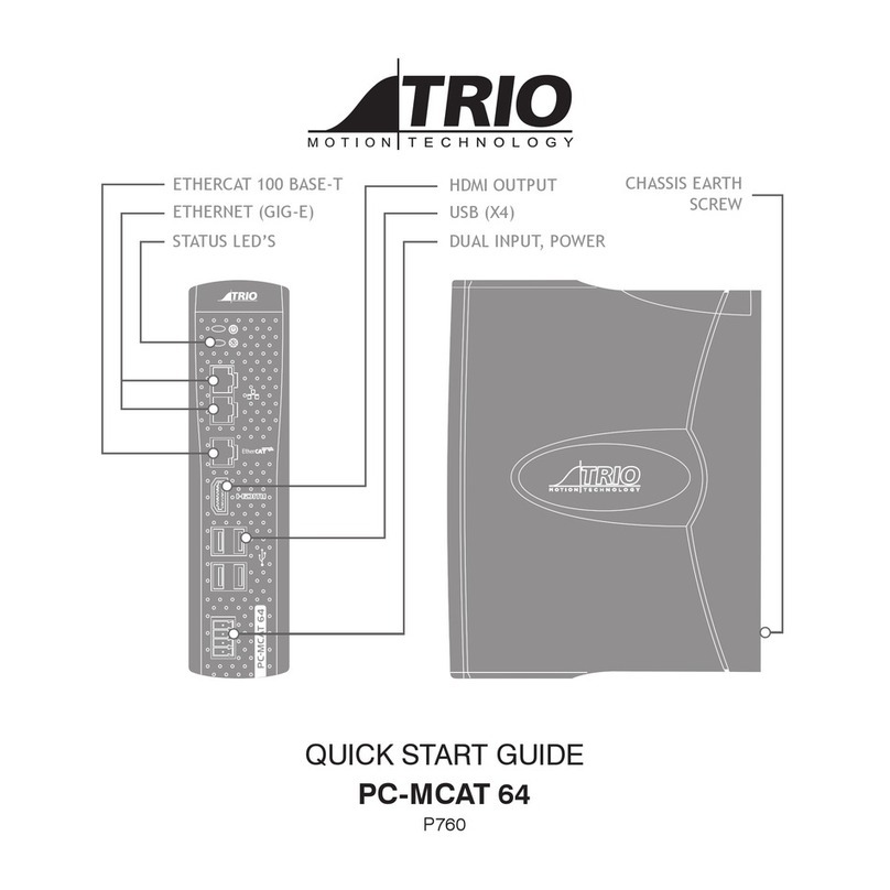
Trio Motion
Trio Motion PC-MCAT 64 quick start guide
