Regin AL24A2D User manual

3076C DEC 2000
AL24A2/D / ALD24A2/D
Tel +46 (0)31 720 02 00 Fax +46 (0)31 720 02 50
Box 116
428 22 KÅLLERED SWEDEN
!
INSTRUKTION INSTRUKTION
78910 11 12
123456
52
,
5
74
85
SETPOINT P-BAND
NEUTRAL
ZONE
AL24-A2/D
REGIN
1
2
3
4
5
6
7
8
9
10
11
12
Fig 1
7
8
AL24A2/D /
ALD24A2/D
1
2
1
2
TBI-....
TG-....
1 2 3 4 A
B
Fig 2
IMPORTANT: Read these
instructions before installation
and wiring of the product.
Supply 24V AC
Neutral 24V AC
Output Y1 0..10V
Signal GND
Output Y2 0..10V
N/C
Signal GND
Main sensor
SPC
N/C
N/C
N/C
External setpoint for panel
mountingusingaTBI-...
Controller with two 0..10V outputs
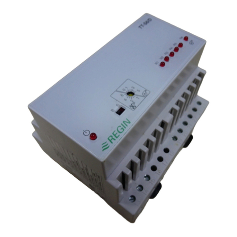
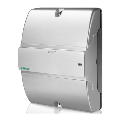
The AL24A2/D, ALD24A2/D is a compact controller for heating or
cooling in ventilation-/airhandling systems and is available with
(ALD) or without (AL) temperature monitor display. The units are
designed to be fitted on a DIN-rail in a panel. All settings are
accessed from the front. The outputs range between 0...10V. The
mode of operation can be either P or PI.
The P-band is adjustable between 2...100 K and I-time can be set
to 1 or 10 minutes.
Installation
Mount this unit on a DIN-rail in a panel.
Ambient temperature, running 0..50°C
Ambient humidity max 90% RH
Degree of protection IP20
Wiring
Supply voltage
24V AC ±15%, 50-60Hz.Power consumption 2VA
Terminal 1 Supply voltage 24 V AC
Terminal 2 System neutral 24 V AC
Outputs
Y1 has heating function only while Y2 can be set to work as either
heating or cooling output (see
function select switch
, SW4).
2 x 0..10V DC, 1mA
Load impedance min 10 KOhm
Terminal 3 Output Y1 0-10 V
Terminal 5 Output Y2 0-10 V
Terminal 4 Signal GND
External setpoint
If external setpoint is desired, connect a setpoint unit (e.g. TBI) as
shown in fig 2. Set SW3 to ’external setpoint’.
SPC (SetPoint Control)
Using an external signal between 0..10V on the SPC input, the
setpoint can be offset up or down. At 5V DC on this terminal, no
change is made to the setpoint. At 0V, setpoint is offset with -15K
and at 10V with +15K.
Terminal 9 0..10V input equals to offset SP with ±15K (SPC)
Terminal 7 Signal GND
Settings
Setpoint
0..30°C. Adjust with left knob on front of the casing.
P-Band
Adjustable with middle knob between 2..100K.
Neutral zone
The neutral zone is adjustable with rightmost knob between
0..5 K and determines the relative starting point for the cooling
function. The cooling output is allowed to increase only when
temperature rises above setpoint + current neutral zone. This
makes the overall system more stable and prevents hunting.
Function select switch
SW1 Mode A = P-controller
B = PI-controller *
SW2 I-Time A = 1 min *
B = 10 min
SW3 Setpoint A = Internal *
B = External
SW4 Y2 Mode A = Cooling function
B = Heating function *
* = Factory setting
Display
The ALD24A2/D controller also has a display showing the
actual temperature at the connected sensor. The measuring
range is 0..30°C and can not be altered.
Indicators
This controller has three LED indicators. The leftmost indicates
power, the middle and rightmost indicate output voltage levels
on Y1 and Y2 respectively. The LED brightness on these two
LEDs is proportional to output level.
Technical support
Consult your local Regin Dealer.
EMC emission and immuniy standard
This product conforms with the requirements of European EMC
standards CENELEC EN50081-1 och EN50082 - 1 and carries
the CE mark.

3076C DEC 2000
AL24A2/D / ALD24A2/D
Tel +46 (0)31 720 02 00 Fax +46 (0)31 720 02 50
Box 116
428 22 KÅLLERED SWEDEN
INSTRUKCJA INSTRUKCJA
78910 11 12
123456
52
,
5
74
85
SETPOINT P-BAND
NEUTRAL
ZONE
AL24-A2/D
REGIN
1
2
3
4
5
6
Zasilanie 24V AC
Masa 24V AC
Wyjcie Y1 0..10V
Masa sygna³owa
Wyjcie Y2 0..10V
Nieu¿ywany
7
8
9
10
11
12
Masa sygna³.
Czujnik g³ówny
SPC
Nieu¿ywany
Nieu¿ywany
Nieu¿ywany
Rys. 1
7
8
AL24A2/D /
ALD24A2/D
Nastawa zewn. za pomoc¹ modu³u
nastawczego TBI-... do monta¿u
panelowego
1
2
1
2
TBI-....
TG-....
1 2 3 4 A
B
Rys. 2
Regulator z dwoma wyjciami 0..10V
AL24A2/D, ALD24A2/D jest kompaktowym regulatorem
przeznaczonym do sterowania ogrzewaniem lub ch³odzeniem w
systemach klimatyzacji i wentylacji. Urz¹dzenie dostarczane jest z
wywietlaczem temperatury (model ALD) lub bez wywietlacza (model
AL). Regulator przeznaczony do monta¿u w panelu na szynie DIN.
Wszystkie pokrêt³a nastawcze i prze³¹czniki wyboru funkcji znajduj¹
siê na frontowej cianie urz¹dzenia. Wyjcia 0...10V. Mo¿liwoæ
wyboru funkcji sterowania P lub PI.
Pasmo P regulowane w zakresie 2...100 K,
Ustawienia czasu I: 1 lub 10 minut.
Monta¿
Urz¹dzenie nale¿y montowaæ w panelu na szynie DIN
Temperatura otoczenia: od 0 do 50°C
Wilgotnoæ otoczenia maks. 90% RH
Stopieñ ochrony IP20
Pod³¹czenia
Zasilanie
24V AC ±15%, 50-60Hz. Pobór mocy 2VA
Zacisk 1 Zasilanie 24 V AC
Zacisk 2 Masa zasilania 24 V AC
Wyjcia
Y1 pe³ni funkcjê sterowania ogrzewaniem jedynie, gdy wyjcie Y2
mo¿e byæ ustawione w tryb sterowania ogrzewaniem lub ch³odzeniem
(patrz Funkcje prze³¹cznika wyboru : SW4).
2 x 0..10V DC, 1mA
Impedancja obci¹¿eniowa min 10 kOhm
Zacisk 3 Wyjcie Y1 0-10 V
Zacisk 5 Wyjcie Y2 0-10 V
Zacisk 4 Masa sygna³owa GND
Nastawa zewnêtrzna
W przypadku potrzeby korzystania z nastawy zewnêtrznej, nale¿y
pod³¹czyæ modu³ nastawczy (np. TBI), jak pokazano na rys.2 i
ustawiæ prze³¹cznik wyboru funkcji SW3 na pozycjê nastawa
zewnêtrzna (B).
SPC (Sterowanie wartoci¹ zadan¹)
Nastawa mo¿e byæ dokonywana zdalnie, za pomoc¹ sygna³u
zewnêtrznego 0...10 V. Sygna³ równy 5 V nie powoduje przesuniêci¹,
wy¿sze napiêcie podnosi, a ni¿sze obni¿a wartoæ zadan¹. Zmiana
napiêcia o +/- 5V powoduje przesuniêcie nastawy o +/-15 K.
Zacisk 9 SPC (sterownie wartosci¹ zadan¹) wejcie 0..10V
Zacisk 7 Masa sygna³owa
Ustawienia
Nastawa
W zakresie 0..30°C. Nastawa przy pomocy pokrêt³a znajduj¹cego
siê po lewej stronie, na ciance frontowej urz¹dzenia.
Pasmo P
Ustawienie przy pomocy rodkowego pokrêt³a, w zakresie
2..100K.
Strefa neutralna
Ustawienie przy pomocy pokrêt³a znajduj¹cego siê po prawej
stronie, w zakresie 0..5 K. Ustawienie strefy neutalnej wp³ywa na
punkt zadzia³ania sekwencji ch³odzenia, co oznacza, ¿e sygna³
wyjciowy zaczyna wzrastaæ kiedy temperatura pomieszczenia
przekroczy nastawê o wartoæ strefy neutralnej. Funkcja ta
zapewnia stabilniejsz¹ pracê systemu.
Funkcje prze³¹czników wyboru
SW1 Funkcja sterowania A = Funkcja regulatora P
B = Funkcja regulatora PI *
SW2 Czas I A = 1 min *
B = 10 min
SW3 Nastawa A = Wewnêtrzna *
B = Zewnêtrzna
SW4 Y2 Tryb A = Funkcja ch³odzenia
B = Funkcja ogrzewania *
* = ustawienie fabryczne
Wywietlacz
Model ALD24A2/D jest wyposa¿ony w wywietlacz pokazuj¹cy
aktualn¹ temperaturê mierzon¹ przez czujnik g³ówny. Zakres
pomiarowy wy³¹cznie od 0 do 30°C.
Sygnalizacja
Regulator posiada trzy diody sygnalizacyjne. Dioda z lewej strony
sygnalizuje zasilanie, rodkowa i prawa wskazuje odpowiednio
poziom sygna³ów wyjciowych na Y1 i Y2 . Jasnoæ wiat³a tych
diód jest proporcjonalna do poziomu sygna³u.
Pomoc techniczna
Prosimy o kontakt z lokalnym przedstawicielem firmy Regin.
Kompatybilnoæ EMC
Urz¹dzenie spe³nia wymagania norm europejskich w zakresie
Kompatybilnoci Elektromagnetycznej CENELEC EN 50081-1 i
EN 50082-1 i posiada znak CE.
!
UWAGA: Przed pod³¹czeniem
regulatora dok³adnie przeczytaj
tê instrukcjê.
3076C DEC 2000
AL24A2/D / ALD24A2/D
Tel +46 (0)31 720 02 00 Fax +46 (0)31 720 02 50
Box 116
428 22 KÅLLERED SWEDEN
BEDIENUNGSANLEITUNG BEDIENUNGSANLEITUNG
!
WICHTIG: Lesen Sie die
Bedienungs-anleitung bevor Sie
den Regler instalieren und
Verdrahten.
78910 11 12
123456
52
,
5
74
85
SETPOINT P-BAND
NEUTRAL
ZONE
AL24-A2/D
REGIN
1
2
3
4
5
6
Versorgung 24V AC
Neutral 24V AC
Ausgang Y1 0..10V
Signal GND
Ausgang Y2 0..10V
N/C
7
8
9
10
11
12
Signal GND
Hauptfühler
SPC
N/C
N/C
N/C
Fig 1
7
8
AL24A2/D /
ALD24A2/D
1
2
1
2
TBI-....
TG-....
1 2 3 4 A
B
Fig 2
Regler mit zwei 0...10V Ausgängen
Der AL24A1/D, ALD24A1/D ist ein Kompaktregler für Heizung- oder
Kühlung mittels Ventilatoren oder in Lüftungsanlagen und ist mit
(ALD) oder ohne (AL) Temperaturanzeige erhältlich. Die Regler
sind für Hutschienenmontage geeignet. Alle Einstellungen können
von der Vorderseite gemacht werden. Der Ausgang ist 0...10 V. Der
Regler kann als P oder als PI Regler arbeiten
Das P-band ist zwischen 2...100 K und I-Zeit zwischen 1 oder 10
Minuten einstellbar.
Einbau
Montieren Sie den Regler auf eine Hutschiene.
Umgebungstemperatur, Betrieb 0..+50°C
Umgebungsfeuchte max 90% RH
Schutzart IP20
Verdrahtung
Versorgungsspannung
24V AC ±15%, 50-60Hz. Leistungsaufnahme 2VA.
Klemme 1 24VAC
Klemme 2 24V AC System neutral
Ausgänge
Y1 ist immer ein Heizausgang, Y2 kann als Heizungs- oder
Kühlausgang verwendet werden. (siehe Funktionswahlschalter,
SW4).
2 x 0..10V DC, 1mA
Lastwiderstand min 10 KOhm
Klemme 3 Ausgang Y1 0-10 V
Klemme 5 Ausgang Y2 0-10 V
Klemme 4 Signal GND
Externer Sollwert
Wird ein externer Sollwert benötigt (z.B. TBI) verbinden Sie diesen
wie in Fig 2. gezeigt. Stellen Sie den SW3 auf ’Externen Sollwert’.
SPC (Sollwertschiebung)
Mit einem externen Signal zwischen 0..10V am SPC-Eingang, kann
der Sollwert nach oben oder unten geschoben werden. Bei Gleich-
spannung von 5V wird keine Änderung am Sollwert vorgenommen,
bei 0V wird der Sollwert mit -15K und bei 10V mit +15K gesetzt.
Dazwischen wird linear geschoben.
Klemme 9 0..10V Entspricht der Schiebung mit ±15K (SPC)
Klemme 7 Signal GND
Einstellungen
Sollwert
0..30°C Einstellbar mit dem linkem Frontpoti.
P-Band
2..100K. Einstellen mit dem mittleren Poti.
Neutrale Zone
Die Neutrale Zone ist zwischen 0...3 K einstellbar (siehe Figur 1)
und beschreibt den relativen Startpunkt für die Kühlfunktion. Der
Kühlausgang steigt nur dann, wenn die Temperatur über dem
Sollwert + der aktuellen neutralen Zone steigt. Dies macht das
Regelsystem stabiler und verhindert Pendelungen.
Funktionswahlschalter:
SW1 Modus A = P-Regler
B = PI-Regler *
SW2 I-Zeit A = 1 min *
B = 10 min
SW3 Sollwert A = Intern *
B = Extern
SW4 Y2 Mode A = Funktion kühlen
B = Funktion heizen *
* = Werkseinstlg.
Anzeige
Der ALD24A2/D Regler hat auch eine Anzeige welche die aktuelle
Temperatur am angeschlossenen Fühler anzeigt. Der
Messbereich liegt zwischen 0..30°C und kann verändert werden.
Meldeleuchten
Der Regler hat drei Meldeleuchten. Die linke zeigt die
Netzspannung an, die mittlere und die rechte (je nach Ausgang Y1
oder Y2) zeigen die Ausgangsspannung an. Die LED-
Leuchtstärke ist direkt proportional zum Ausgangssignal.
Technische Unterstützung
Bei Ihrem lokalen REGIN Händler.
EMC emission and immuniy standard
Dieses Produkt entspricht den Anforderungen des
Euro-päischen Standards CENELEC EN50081-1 und
EN50082 - 1 und trägt das CE Zeichen.
Externer Sollwert für
Schaltschrankmontage mit TBI-...
This manual suits for next models
3
Table of contents
Languages:
Other Regin Controllers manuals

Regin
Regin Corrigo User manual

Regin
Regin TTC40FX User manual

Regin
Regin Corrigo E User manual

Regin
Regin TTC 2000 User manual

Regin
Regin PCMTV50-F20 User manual

Regin
Regin XCA152W-4 User manual

Regin
Regin RVA25-24A User manual

Regin
Regin RVAZ4L1-230 User manual

Regin
Regin RDAS7S-24C User manual

Regin
Regin RDAS5-24C User manual

Regin
Regin RVAN18-230 User manual

Regin
Regin RVAZ4-230 User manual

Regin
Regin RVAPC-24A User manual

Regin
Regin RVAB4-24 User manual

Regin
Regin Optigo OP5U User manual

Regin
Regin CORRIGO L10 User manual

Regin
Regin REGIO ARDO User manual

Regin
Regin REGIO RC-F User manual

Regin
Regin TTC25X User manual

Regin
Regin RDAS7S Series User manual