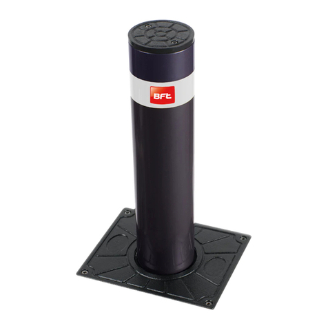
BFT RANCH C 275/600CN Guide

ISTRUZIONI PER INSTALLAZIONE
INSTRUCTIONS FOR INSTALLATION
DISSUASORE FISSO CON O SENZA FLANGIA
FIX BOLLARD WITH OR WITHOUT FANGE
Attenzione! Leggere attentamente le“Avvertenze”all’interno! Caution! Read“Warnings”inside carefully!
07-09-20
DISSUASORE
BOLLARD
FLANGIA
FLANGE
RANCH C 275/600CN
RANCH C 275/800CN
D812819 00550_03

2 - RANCH C 275/600CN - RANCH C 275/800CN
D812819 00550_03
INTRODUZIONE
Leggere attentamente il libretto prima di installare il
prodotto, utilizzarlo e prima di eseguire manutenzione
ordinaria o straordinaria.
Le indicazioni precedute da questo simbolo
contengono informazioni di particolare importanza, il loro
mancato rispetto può comportare la perdita della garanzia
contrattuale.
LE OPERAZIONI CHE EFFETTUATE IN MODO NON CORRETTO
POSSONO PRESENTARE RISCHI SONO INDICATE CON I SIMBOLI:
FOLGORAZIONE SCHIACCIAMENTO
Il libretto di INSTALLAZIONE USO E MANUTENZIONE è
destinato agli installatori, agli utilizzatori ed agli operatori
della manutenzione.
La Ditta non è responsabile per danni arrecati a persone,
animali o cose dovuti ad applicazioni che superano i limiti
indicati nella scheda tecnica allegata o dall’uso diverso da
quello per cui il prodotto è stato progettato.
ATTENZIONE! Seguire tutte le istruzioni, un’installazione
non corretta può provocare lesioni gravi.
SICUREZZA GENERALE
• Conservare le istruzioni per allegarle al fascicolo tecnico e per
consultazioni future.
• L’installazione deve essere eseguita da personale qualicato
(installatore professionale, secondo EN12635), nell’osservanza
della Buona Tecnica e delle norme vigenti.
• Il cavo di alimentazione, durante l’installazione, deve essere
sguainatoinmododa permettereil collegamentodel conduttore
diterraall’appropriatomorsettolasciandoperòiconduttoriattiviil
piùcorti possibile. Ilconduttore diterra deve esserel’ultimo a ten-
dersi in caso di allentamento del dispositivo di ssaggio del cavo.
• Smaltire i materiali di imballo (plastica, cartone, polistirolo, ecc.)
secondo quanto previsto dalle norme vigenti. Non lasciare buste
di nylon e polistirolo a portata dei bambini.
• Togliere l’alimentazione elettrica, prima di qualsiasi intervento
sull’impianto. Scollegare anche eventuali UPS o gruppi di conti-
nuità se presenti.
• Vericare che a monte della rete di alimentazione, vi sia un
interruttore dierenziale con soglia da 0,03A.
• Le uscite non sono a bassissima tensione di sicurezza (SELV),
pertanto non devono essere parti raggiungibili.
• Usare esclusivamente parti originali per qualsiasi manutenzione
o riparazione.
• Non eseguire alcuna modica ai componenti dell’automazione
se non espressamente autorizzata dalla Ditta.
• Non permettere ai bambini di giocare con l’apparecchio.
• L’apparecchio può essere utilizzato da bambini di età non infe-
riore a 8 anni e da persone con ridotte capacità siche, sensoriali
o mentali, o prive di esperienza o della necessaria conoscenza,
purché sotto sorveglianza oppure dopo che le stesse abbiano
ricevuto istruzioni relative all’uso sicuro dell’apparecchio e alla
comprensione dei pericoli ad esso inerenti.
• La pulizia e la manutenzione destinata ad essere eettuata
dall’utilizzatore non deve essere eettuata da bambini senza
sorveglianza.
• Tutto quello che non è espressamente previsto in queste istru-
zioni, non è permesso.
GENERALITA’
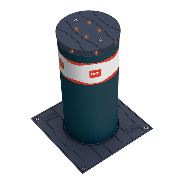
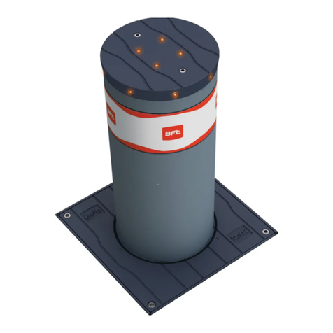
Il dissuasore è la soluzione ideale per la protezione e la
salvaguardia di aree private nel rispetto dei moderni canoni
di arredo urbano.
DATI TECNICI
Dimensioni totali............. Ø500 x 960H (RANCH C 275/600CN)
..............................................Ø500 x 1160H (RANCH C 275/800CN)
Stelo..................................................Ø273 x h. 600/800 x sp. 6 mm
Flangia (optional)........................................................ 470 x 470 mm
Alimentatore luci (optional) .................24 Vac ±10%, 50-60 Hz
Peso netto dissuasore .................. 40 kg (RANCH C 275/600CN)
............................................................... 48 kg (RANCH C 275/800CN)
Peso lordo dissuasore................... 46 kg (RANCH C 275/600CN)
............................................................... 55 kg (RANCH C 275/800CN)
Peso netto angia (optional).................................................... 15 kg
Peso lordo angia (optional).................................................... 18 kg
INTRODUCTION
Please read it carefully before installing the appliance,
before using it and before routine or extraordinary
maintenance work.
The notices preceded by this symbol provide important
information, the non-compliance with such instructions
voids the manufacturer’s guarantee.
OPERATIONS THAT, IF NOT CARRIED OUT CORRECTLY, CAN BE RISKY,
ARE INDICATED WITH THE FOLLOWING SYMBOLS
ELECTROCUTION S CRUSHING
The INSTALLATION, USE AND MAINTENANCE handbook is
for installers, users and maintenance engineers.
The Company is not liable for injury to people or animals or
damage to things in the case of applications that exceed the
limits specied on the enclosed technical data sheet or by
a use dierent from what the appliance has been designed.
Warning! Observe all the instructions, improper installation
can result in serious injury.
GENERAL SAFETY
• Keep hold of instructions so that you can attach them to the
technical le and keep them handy for future reference.
• Installation must be carried out by qualied personnel (pro-
fessional installer, according to EN 12635), in compliance with
Good Practice and current code.
• During installation, the power cable must be stripped to allow
the earth wire to be connected to the relevant terminal, while
leaving the live wires as short as possible. The earth wire must
be the last to be pulled taut in the event the cable’s fastening
device comes loose.
• Scrap packing materials (plastic, cardboard, polystyrene etc)
according to the provisions set out by current standards. Keep
nylon or polystyrene bags out of children’s reach.
• Disconnect the electrical power supply before carrying out any
work on the installation. Also disconnect any UPS, if tted.
• Check that a dierential switch with a 0,03A threshold is tted
just before the power supply mains.
• The outputs are not of type SELV (separated extra-low voltage),
therefore it must not be possible to reach them.
• Only use original parts for any maintenance or repair operation.
• Do not modify the automation components, unless explicitly
authorised by the Company.
• Do not allow children to play with the equipment.
•Theequipmentmaybeusedbychildrenagedover8yearsoldand
by people with reduced physical, sensory or mental capabilities,
orwithoutexperienceorthenecessaryknowledge,providedthey
are supervised or after they have received instructions relating to
the safe use of the equipment and have understood the dangers
inherent in it.
• Cleaning and maintenance meant to be performed by the user
must not be performed by unsupervised children.
• Anything which is not expressly provided for in the present
instructions, is not allowed.
GENERAL
The deterrent bollard is the ideal solution for protecting and
safeguard private areas in compliance with modern urban
furnishing requirements.
TECHNICAL SPECIFICATIONS
Overall dimensions......... Ø500 x 960H (RANCH C 275/600CN)
..............................................Ø500 x 1160H (RANCH C 275/800CN)
Rod.................................................... Ø273 x h. 600/800 x th. 6 mm
Flange (optional)......................................................... 470 x 470 mm
Light power supply (optional) .............24 Vac ±10%, 50-60 Hz
Bollard net weight ....................... 40 kg (RANCH C 275/600CN)
............................................................... 48 kg (RANCH C 275/800CN)
Bollard gross weight .................... 46 kg (RANCH C 275/600CN)
............................................................... 55 kg (RANCH C 275/800CN)
Flange net weight (optional) .................................................. 15 kg
Flange gross weight (optional) .............................................. 18 kg
ATTREZZATURE - EQUIPMENT
17 mm
M8x20
Ø8
M8
6 mm
6 mm
13 mm 8 mm
COMPOSIZIONE DEL KIT - KIT COMPOSITION COMPOSIZIONE DEL KIT - KIT COMPOSITION
M8x20 Ø8
M8
Ø
8
M8
M10x30
M8x16
Ø8
M10
M12x1.5
A
DIMENSIONI D’INGOMBRO
OVERALL DIMENSIONS
Livello stradale
Ground level
Ø273
360
200
Ø500
DISSUASORE SENZA FLANGIA / BOLLARD WITHOUT FLANGE
FLANGIA / FLANGE
B
PREPARAZIONE DEL DISSUASORE
BOLLARD PREPARATION
6 mm
x 3
13 mm
RANCH C 275/600CN - RANCH C 275/800CN - 3
D812819 00550_03
RANCH C 275/600CN - RANCH C 275/800CN
600 (RANCH C 275/600CN)
800 (RANCH C 275/800CN)

C
INSTALLAZIONE
INSTALLATION
600 (*)
600 (*)
CEMENTO (non fornito)
CONCRETE (not supplied)
400 (*)
600 (*)
600 (*)
(*) VALORE INDICATIVO / INDICATIVE VALUE
CAVO LUCI (solo versione con luci)
LIGHT CABLE (light version only)
1 2
Livello stradale
Ground level
20075
275
Ø273
470
470
DISSUASORE CON FLANGIA / BOLLARD WITH FLANGE
D
DIMENSIONI D’INGOMBRO
OVERALL DIMENSIONS
E
PREPARAZIONE DEL DISSUASORE
BOLLARD PREPARATION
21 4
3
M10x30
M10
8 mm
17 mm
M12x1,5
M10x30
M10
17 mm
x2
M8x16
Ø8
x 3
6 mm
4 - RANCH C 275/600CN - RANCH C 275/800CN
D812819 00550_03
600 (RANCH C 600)
800 (RANCH C 800)

CAVO LUCI (solo versione con luci)
LIGHT CABLE (light version only)
600 (*)
600 (*)
400 (*)
230Vac
Linea monofase
Single phase line
Fusibile / Fuse
230V - 1A-T
24Vac
Cavo luci
Light cable
Prima di eettuare qualsiasi intervento sull’impianto togliere
l’alimentazione elettrica mediante un sezionatore.
Always disconnect the electricity with a cut-o switch before
attempting any work on the system.
ATTENZIONE 230V
ATTENTION 230V
VERSIONE CON LUCI / LIGHT VERSION
G
F
CONNESSIONI ELETTRICHE CAPPELLO LUCI (Optional)
ELECTRICAL CONNECTIONS LIGHT CAP (Optional)
INSTALLAZIONE
INSTALLATION
1 2
1234
() Non collegare / Do not connect
brown
black
blue
white or
yellow/green
Buzzer ()
Light
Buzzer ()
Light
Connettore controparte (non fornito)
Counterpart connector (not supplied)
- N° 1 AMP cod. 282088-1
Connettore femmina/female connector
- N° 4 AMP cod. 183035-1
Contatti/pins
- N° 4 AMP cod. 281934-2
Guarnizioni cavi/wire seals
Dal cappello luci
From light cap
CEMENTO (non fornito)
CONCRETE (not supplied)
600 (*)
600 (*)
(*) VALORE INDICATIVO / INDICATIVE VALUE
RANCH C 275/600CN - RANCH C 275/800CN - 5
D812819 00550_03
P800104 ALLU

SICUREZZA GENERALE
• É vietato qualsiasi uso diverso da quello per cui il prodotto è
stato progettato.
• Tenere bambini, persone e cose fuori dal raggio d’azione
dell’automazione, in particolare durante il funzionamento.
• Icollegamentielettrici devonoessereeettuatinel rispetto delle
disposizioni legislative vigenti.
• Gli elementi costruttivi della macchina devono essere in accordo
conleseguentiDirettiveEuropee:2014/35/UE,2014/30/UE,eloro
modiche successive. Per tutti i Paesi extra CEE, oltre alle norme
nazionali vigenti, per un buon livello di sicurezza è opportuno
rispettare anche le norme sopracitate.
• La Ditta declina qualsiasi responsabilità dall’inosservanza della
Buona Tecnica nella installazione del dispositivo descritto nel
presente manuale.
• Noninstallareilprodottoinatmosferapotenzialmenteesplosiva
o in presenza di rischio di incendio.
• Togliere l’alimentazione elettrica, prima di qualsiasi intervento
sull’impianto. Scollegare anche eventuali batterie tampone se
presenti.
• Prevedere sulla rete di alimentazione dell’automazione, un
interruttore o un magnetotermico onnipolare con distanza di
apertura dei contatti uguale o superiore a 3,5 mm. Prevedere
un dispositivo di sezionamento adeguato anche per le batterie
tampone.
• Vericare che a monte della rete di alimentazione, vi sia un
interruttore dierenziale con soglia da 0.03A.
• Vericare se l’impianto di terra è realizzato correttamente.
• Usareesclusivamentepartioriginaliperqualsiasimanutenzione
o riparazione. La Ditta declina ogni responsabilità ai ni della
sicurezzaedelbuonfunzionamentodell’automazionesevengono
impiegati componenti di altri produttori.
• Non eseguire alcuna modica ai componenti dell’automazione
se non espressamente autorizzata dalla Ditta.
• Smaltirei materiali di imballo (plastica, cartone, polistirolo,ecc.)
secondo quanto previsto dalle norme vigenti. Non lasciare buste
di nylon e polistirolo a portata dei bambini.
• Tutto ciò che non è espressamente previsto in queste istruzioni,
non è permesso.
• La pulizia e la manutenzione destinata ad essere eettuata
dall’utilizzatore non deve essere eettuata da bambini senza
sorveglianza.
AVVERTENZE
La Ditta non risponde dei danni causati dall’inosservanza
delle norme di installazione e delle indicazioni riportate in
questo manuale.
Ledescrizioniele illustrazionidelpresentemanualenonsono
impegnative.Lasciandoinalteratelecaratteristicheessenziali
del prodotto, la Ditta si riserva di apportare in qualunque
momento le modiche che essa ritiene convenienti per mi-
glioraretecnicamente,costruttivamenteecommercialmente
il prodotto, senza impegnarsi ad aggiornare la presente
pubblicazione.
MANUTENZIONE ORDINARIA (OGNI SEI MESI)
• La manutenzione deve essere eseguita solo da personale
qualicato.
• Prima di eettuare qualsiasi intervento sull’impianto togliere
l’alimentazione elettrica mediante un sezionatore lucchettabile.
• Controllare visivamente lo stato generale di conservazione
delle parti esterne del dissuasore.
• Controllare che la pellicola retroriettente dello stelo non
sia usurata.
• Controllare la funzionalità delle luci.
• Vericare l’integrità delle connessioni elettriche e dei cablaggi,
in particolare lo stato delle guaine isolanti.
• Registrare gli interventi di manutenzione nell’apposito
modulo.
GENERAL SAFETY
• Any use other than that expressly permitted is prohibited.
•Keepadults,childrenandpropertyoutofrangeoftheautomated
system, especially while it is operating.
• All electrical connections must be done in compliance with
current laws.
•The construction components of this product must comply with
thefollowingEuropeanDirectives:2014/35/UE,2014/30/UE,and
subsequentamendments.Asforallnon-EECcountries,theabove-
mentioned standards as well as the current national standards
should be respected in order to achieve a good safety level.
• The Company declines all responsibility for any consequences
resulting from failure to observe Good Technical Practice when
installing the device described in the present manual.
• Do not install the product in potentially explosive atmosphere
or wherever there is a re risk.
• Disconnect the electrical supply before carrying out any work
on the installation. Also disconnect any buer batteries, if tted.
• Fit an omnipolar or magnetothermal switch on the mains power
supply,havingacontactopeningdistanceequaltoorgreaterthan
3,5mm.Alsotanadequatecut-outdeviceforthebuerbatteries.
• Check that a dierential switch with a 0.03A threshold is tted
just before the power supply mains.
• Check that earthing is carried out correctly.
• Only use original parts for any maintenance or repair operation.
The Company declines all responsibility with respect to the
automation safety and correct operation when other producers’
components are used.
• Do not modify the automation components, unless explicitly
authorised by the Company.
• Scrap packing materials (plastic, cardboard, polystyrene etc)
according to the provisions set out by current standards. Keep
nylon or polystyrene bags out of children’s reach.
• Anything which is not expressly provided for in the present
instructions, is not allowed.
• Cleaning and maintenance meant to be performed by the user
must not be performed by unsupervised children.
WARNINGS
The Company is not to be held responsible for any damage
resulting from failure to observe the installation standards
and the instructions contained in the present manual.
The descriptions and illustrations contained in the present
manual are not binding. The Company reserves the right to
make any alterations deemed appropriate for the technical,
manufacturingand commercialimprovement of theproduct,
while leaving the essential product features unchanged, at
any time and without undertaking to update the present
publication.
ROUTINE MAINTENANCE (EVERY 6 MONTHS)
• Maintenance must be carried out by qualied personnel only.
• Always disconnect the electricity before attempting any work
on the system with a lockable cut-o switch.
• Visually check the overall state of wear and tear of the external
parts of the deterrent bollard.
• Make sure the rear-reecting lm is not worn.
• Make sure the lights work.
• Check that electrical connections and cabling are intact, making
extra sure that insulating sheaths are undamaged.
• Record maintenance in the dedicated form.
6 - RANCH C 275/600CN - RANCH C 275/800CN
D812819 00550_03

Dati impianto / Installation data
Installatore / Installer
Cliente / Customer
Matricola / Serial number
Data installazione
Installation date
Data attivazione
Activation date
Luogo / Location
Dati manutenzione / Maintenance date
Nr. Data • Date Descrizione intervento • Intervention description Firma •Signature
1
Tecnico • Technician
Cliente • Customer
2
Tecnico • Technician
Cliente • Customer
3
Tecnico • Technician
Cliente • Customer
4
Tecnico • Technician
Cliente • Customer
5
Tecnico • Technician
Cliente • Customer
6
Tecnico • Technician
Cliente • Customer
7
Tecnico • Technician
Cliente • Customer
8
Tecnico • Technician
Cliente • Customer
9
Tecnico • Technician
Cliente • Customer
10
Tecnico • Technician
Cliente • Customer
REGISTRO DI MANUTENZIONE / MAINTENANCE LOG
RANCH C 275/600CN - RANCH C 275/800CN - 7
D812819 00550_03

INSTALLATORE
INSTALLER
DATA
DATE
www.bftme.ae
This manual suits for next models
1
Table of contents
Other BFT Control System manuals

BFT
BFT GIOTTO BT A ULTRA 36 User manual

BFT
BFT XPASS B 1200C User manual

BFT
BFT MOOVI ART 90 User manual

BFT
BFT STOPPY MBB 219-500.C Parts list manual

BFT
BFT XPASS B 330/1200 L Parts list manual

BFT
BFT MOOVI 30S User manual

BFT
BFT XPASS B 800C User manual

BFT
BFT PILLAR B 275/600.6C L Quick start guide

BFT
BFT PHP ADA User manual

BFT
BFT PCA ES N3 User manual