Proteco SWING User manual

SWING
Installation Manual
Automation system for counterweight balanced
(up and over) garage doors Technical Installation Manual

1
1. WARNINGS AND GENERAL SAFETY INSTUCTIONS
This manual contains important safety information.
An incorrect installation or an improper use may cause serious damages to persons or objects.
Read this manual carefully and completely. Pay particular attention to the sections marked by the symbol: .
This indicates that risk to personal injury may occur if not adhered to.
Store this manual safety for future use.
Always disconnect main power supply before operating in the automatic gate.
Make sure that the earth system is perfectly working and always connect the automatic gate to it.
The installation of automatic gates and doors must fully comply with the requirements set forth in 2006/42/EC Directive, with particular
reference to EN 12445 and EN 12453 standards.
The final connection to the electrical mains, testing and start-up of the automation must be performed by skilled and qualified personnel
(professional gate installers), who is responsible for carrying out the risks analysis and verifying the compliance of the system with the
current safety standards.
This product is exclusively designed and manufactured for the intended use specified in this manual.
Any other use than stated could compromise the integrity and the safety of the product and therefore is strictly prohibited.
The automation is designed to move driveway gates and not intended to be used for any other purpose.
Do not let children play with the radio transmitters and any other device which could accidentally start the gate automation.
Use exclusively original parts by manufactured by Proteco for maintenance.
Do not carry out any alteration on the components of the automatic gate.
Proteco SRL will not accept liability for any components and/or additional devices used in-conjunction with the automation that has not
been produced exclusively by Proteco.
CE COMPLIANCE DECLARATION
Manufacturer: PROTECO S.r.l.
Address: Via Neive, 77 – 12050 Castagnito (CN) – ITALIA
declares that
IThe product type: SWING Electromechanical gear motor for up and over balanced garage doors
Models: SWING, SWING C
Accessories: E102/C, E102/L, E101
Is built to be integrated into a machine or to be assembled with other machinery to crate a machine under provisions of 2006/42/EC Machinery
Directive, with reference in particular to the following requirements: 1.1.2, 1.1.3, 1.1.5, 1.2.1, 1.2.2, 1.2.3, 1.2.4.1, 1.2.6, 1.3.1, 1.3.4, 1.3.7, 1.3.8.2, 1.3.9,
1.4.1, 1.4.2.1, 1.4.2.2, 1.5.1, 1.5.4, 1.6.1, 1.6.2, 1.6.3, 1.6.4, 1.7.1, 1.7.3, 1.7.4, 1.7.4.1, 1.7.4.2, 1.7.4.3.
ÈIt complies with the essential requirements of EEC Directives:
2006/95/CE Low Voltage Directive
2004/108/CE Electromagnetic Compatibilità Directive
It complies with the essential requirements of EEC Directives:
EN 12453, EN 12445, EN 12604, EN12605, EN 13241-1
EN 55014-1,EN 55014-2
EN 60335-1, EN 60335-2-103
EN 61000-3-2
EN 61000-3-3
The manufacturer also declares that the start-up of the machinery is not permitted unless the machine, in which the product is incorporated or of
which is becoming a component, has been identified and declared as conformed to 2006/42/EC Machinery Directive.
Castagnito, September 14 2015 Marco Gallo
C.E.O.

2
E 101
E 102/C
E 102/L
96
100
620
2.1 Technical Specifications
2. PRODUCT DESCRIPTION AND INTENDED USE
Il motoriduttore SWING è stato studiato per automatizzare porte da garage basculante a contrappeso di tipo residenziale.
Qualsiasi altro uso da quello descritto è da considerarsi improprio e vietato.
Tutti i modelli garantiscono il blocco meccanico della porta con un sistema di ingranaggi irreversibile;
non è pertanto necessario installare alcun tipo di serratura.
In caso di black-out il motoriduttore può essere sbloccato manualmente dall’interno del garage.
2.1 TECHNICAL SPECIFICATIONS
SWING
2.3 Optional Accessories
2.2 Pack Contents
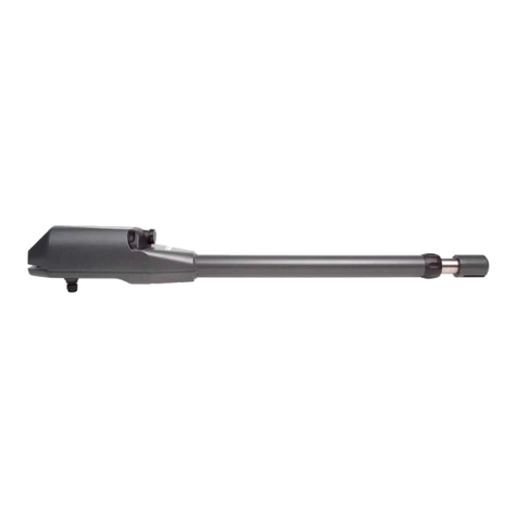
Set of telescopic arms and brackets
for CENTRAL fixing on door
DIMENSIONS
SWING C
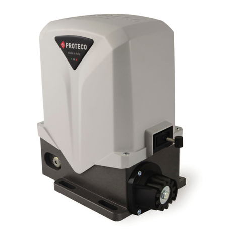
Gearmotor with release system
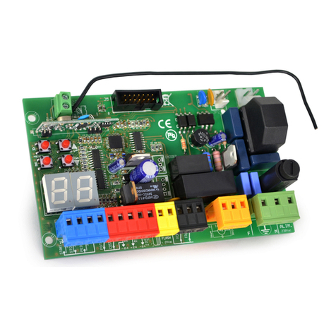
Control panel
+ Base plate 1.2m
+ Limit switch system
Kit for manually release
form outside
Set of telescopic arms and brackets
for lateral fixing on door
Power Supply 230V ~ 50Hz
Current 1.0 A
Moto Power 300 W
Thermic Protection 140°C
Capacitor 10µF
Motor Thrust 645 Nm
Class IP protection 54
Revolutions (speed) 1400 rpm
Opening time 18”
Maximum door surface 8 m²
Working temperature range - 20°C / +50°C
Duty cycle 50%

230 V
50 Hz
3x1.5
2x1.5
1xRG58
4x1
2x1
2x1
3.2.2 ELECTRICAL CABLES SPECIFICATIONS
Use the following cables are required for a correct electrical set-up:
3 x 1.5 for electrical mains 230V
2 x 1.5 for flashing light
1 x RG58 f or external aerial
2 x 1 for transmitting photocell
4 x 1 for receiving photocell
2 x 1 for safety edge
Note: The cables required the electrical set-up (not included in the pack) may vary according
to quantity and type of devices installed.
3.2 Electrical Set-up
3.2.1 STANDARD INSTALLATION
3. INSTALLATION
3.1 Preliminary Checks
Before the installation, to ensure correct working of the automation, please check the followings:
• Make sure the door can be easily moved manually, without frictions or clinging
• Check the weight, dimensions and type of the door is appropriate to this type of automation
• Ensure the door opens smoothly without skids
• Check correct balancing and condition of the door
Any lack or incorrect movement of the door must be fixed before installing the automation system.
Control
panel

43
mc51-11
H
H2/1H2/1
mc51-11
mc51-11
mc51-11
3.3 Gear motor Installation
Fix the base plate on the door according to the type of
doors and measurements as shown here below.
a) Unlock any kind of door blocking system
b)Find the door’s height dimension H by door type (Fig. 1, 2
and 3).
c)Cut the base plate (from the side where there are no
holes on the edge) according to the H dimension.
d)Fix the base plate in the middle of the door (in case of
single motor installation) or on the door’s edges (in case
of twins motor installation) and arrange a solid fastening.
Please refer to 3.4.1 and 3.4.2 sections.
e)Fix the gear motor to the base plate using the four
M8x20 screws supplied; make sure that the transmission
shaft is from 10 to 15 cm lower than the pivoting point of
the door (Fig. 4).
In case of heavy doors o garage doors with pedestrian
shutter in the middle you need to install two motors, one
of each edge of the door (Fig. 5).
Standard up and
over balanced door
Concealed up and
over balanced door
Articulated sections
balanced door
Fig. 1
Fig. 5
Fig. 2
Fig. 3
Fig. 4

5
3.4 Installing the transmission arms
3.4.1 Installing CENTRAL transmission arms set E102/C
(Optional purchase)
a) Fix the transmission arms with toothed ring onto the drive
shaft and fasten with the two M8x8 grub screws (Fig. 6)
b)Get the L arms in to the triangle-shaped brackets with
plastic ring (Fig. 7)
c)Join the L arms to the toothed ring arms by the supplied
coupling pipes (Fig. 8)
d)Fix the triangle-shaped brackets to the doors with the
supplied screws; make sure that bushings are aligned
with the drive shaft (Fig. 9)
e) Insert the flat arms (“swords”) 35x5 in to the L arms (Fig. 10).
The holes must be on the upper side and pointing
towards the door.
f)Fix the flat arms (“swords”) directly to the upper pivots of
the door’s brackets (Fig. 16).
If dimensions or the kind of door don’t allow direct fixing
on the pivots, please use the supplied anchoring
brackets (Fig. 11) and fix them at the same height of the
pivot points of the door (Fig. 12)
g)Fasten the arms by piercing 12 holes as shown in the
picture and fixing the 12 through screws M6x40 and
self-locking nuts (Fig. 13).
Fig. 6
Fig. 7
Fig. 8
Fig. 9
Fig. 11 Fig. 12
Fig. 10
Fig. 13

6
3.4.2 Installing LATERAL transmission arms set E 102/L
(Optional purchase)
a) Fix the toothed ring arm onto the drive shaft and fasten it
with the grub screw M8x8 (Fig. 14).
In case of twin motor installation, repeat procedure on
the opposte side.
b)I Insert the flat arms (“swords”) 35x5 in to the toothed ring
arm (Fig.15)
c)Fix the flat arms (“swords”) directly to the upper pivots of
the door’s brackets (Fig. 16).
If dimensions or the kind of door don’t allow direct fixing
on the pivots, please use the supplied anchoring
brackets (Fig. 11) and fix them at the same height of the
pivot points of the door (Fig. 12)
Fig. 14
Fig. 15Fig. 16

AB
C
D
EF
M
8 Fm
5. ADJUSTING LIMIT SWITCHES
a) Give the control panel an closing command.
b)When the door reaches the closed position give the
control panel a Stop command.
c)Install the cam ring on the driving shaft, pay atten-
tion that pin (D) wouldn’t get stuck between the
two micros.
d)Rotate the ring (B) anti-clockwise so that pin (D) can
activate the closing micro-switch (E).
e)Fasten the grub screw (C) to fix the ring on the drive
shaft in the required position.
f)Place the screw (A) about 17-18 clockwise away
from pin (D).
g)Give the control panel an opening command and
check the correct opening position of the door.
h)If the door doesn’t stop in the correct open position
move screw (A) one or more holes
backward/forward
A: VITE
B: DISCO
C: GRANO
D: PIOLO
E: MICRO DI CHIUSURA
F: MICRO DI APERTURA
4. ELECTRICAL WIRING
Wire motor and limit switches as per below schemes:
Insert electrical cables into the control panel’s case. Please follow the control panel’s instruction manual to proceed with
the correct cable wiring and programming.
Nero
Blu
MOTOR WIRING
Bianco
Verde
Giallo
LIMIT SWITCHES WIRING
Marrone
Marrone CLOSE OPEN

7
zoom A zoom B
1) Unlock motor moving the handle.
2) Insert the steel wire in the eyelet on the motor carter
(zoom A)
3) Get the steel wire into the black sheath.
4) Drive the sheath and the wire to the point where the
pulling system will be fixed.
5) When placing the sheath and the wire make sure it
makes wide and reasonable bends as shown in the
picture.
6) Check the limit of the sheath is close to the motor
(hold the sheath with one hand and straighten the
wire out with the other hand).
7) Fix now the pulling system to the frame.
8) Cut the sheath accordingly.
9) Fasten the wire to the pulling system.
10) Adjust wire’s pulling by its regulator.
6. INSTALLING THE MANUAL RELEASE SYSTM FROM OUTSIDEE 101
(Optional)

7. TESTING THE AUTOMATION AND START UP
Power the system and proceed with a careful checking of the gear motor working, please pay
particular attention to safety devices connected to the automation and to the emergency
manual release systems.
Place the cover on the motor and screw it.
Hand over this instructions manual to the end user and demonstrate the correct use of the automation
and how to release the motor for manual operation of the gate in the event of power cuts.
8. RELEASE PROCEDURE FOR MANUAL OPERATION
Always cut the main power of the system during the release and re-locking procedure to avoid
any accidental activation of the door.
1)Cut off main power to motor
2) Rotate the handle as shown in the beside picture
3) Open the door manually and secure it so that it won’t
move (for example because of a gust of wind) or fall on
people and objects
4) Restore power supply, give a Start command to the
automation and move the release handle back to its
original position.
9. MAINTENANCE
Effettuare almeno semestralmente la verifica funzionale dell’impianto con particolare attenzione
ai dispositivi di sicurezza e di sblocco e alle parti meccaniche in movimento.
10. DISPOSAL
Do not pollute the environment
Alcune parti di questo prodotto possono contenere sostanze inquinanti.
Some components may contain polluting substances. Ensure materials are passed to THE
authorised municipal collection facilities.

11. EXPLODED VIEW DRAWING
Proteco S.r.l. Via Neive, 77 - 12050 CASTAGNITO (CN) ITALY
Tel. +39 0173 210111 - Fax +39 0173 210199 - info@proteco.net - www.proteco.net
Table of contents
Other Proteco Garage Door Opener manuals
Popular Garage Door Opener manuals by other brands

GFA
GFA ELEKTROMAT ST 16.15 installation instructions

Beninca
Beninca VN.S manual

Craftsman
Craftsman 139.53992D owner's manual

Chamberlain
Chamberlain MyQ LM70EVK Instruction manual and installation instructions

Chamberlain
Chamberlain Power Drive Security+ PD752CD owner's manual

Chamberlain
Chamberlain WD832KEV installation instructions

Calimet
Calimet CM5-DCNB instruction manual

DTS
DTS 600 Elite installation manual

Craftsman
Craftsman 139.53669SRT owner's manual

King gates
King gates MINIMODUS Installation and use instructions and warnings

Craftsman
Craftsman 139.53990DS owner's manual

Chamberlain
Chamberlain Power Drive Security+ PD612CD owner's manual