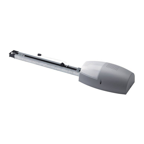
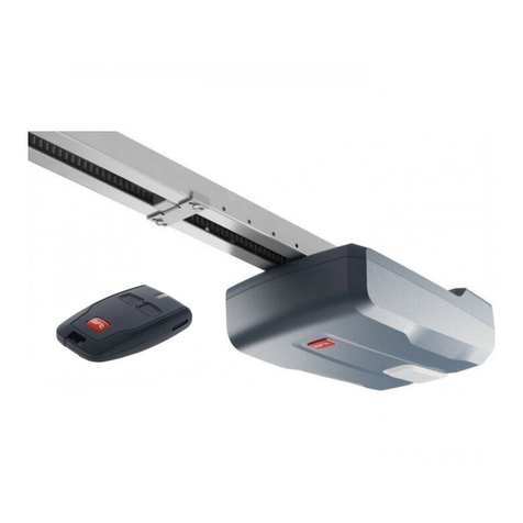
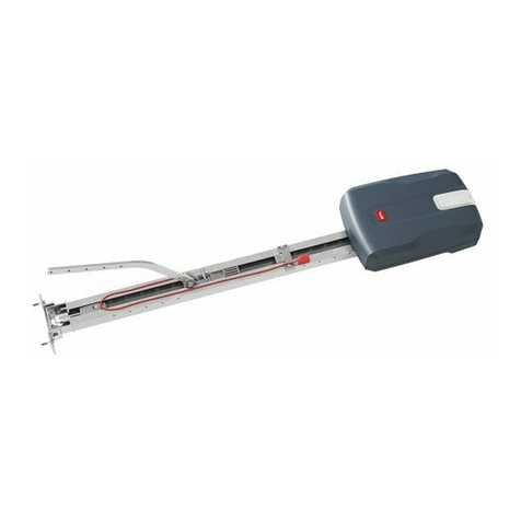
BFT Botticelli VENERE D User manual

ISTRUZIONI D’USO E DI INSTALLAZIONE
INSTALLATION AND USER’S MANUAL
INSTRUCTIONS D’UTILISATION ET D’INSTALLATION
INSTALLATIONS-UND GEBRAUCHSANLEITUNG
INSTRUCCIONES DE USO Y DE INSTALACION
GEBRUIKS- EN INSTALLATIEAANWIJZINGEN
BOTTICELLIVENERE D
BOTTICELLI VENERE D
D811493 00100_01 16-10-08
AUTOMAZIONI PER PORTE BASCULANTI E SEZIONALI
AUTOMATION FOR OVERHEAD AND SECTIONAL GARAGE DOORS
AUTOMATION POUR PORTES BASCULANTES ET SECTIONALES
GARAGENTORANTRIEB FÜR SCHWING UND SEKTIONALTORE
AUTOMATIZACIONES PARA PUERTAS BASCULANTE Y SECCIONALES
AUTOMATISERINGEN VOOR KANTEL- EN SECTIEDEUREN
Attenzione! Leggere attentamente le “Avvertenze” all’interno! Caution! Read “Warnings” inside carefully! Attention! Veuillez lire attentivement les Avertissements qui se trouvent à l’intérieur!
Achtung! Bitte lesen Sie aufmerksam die„Hinweise“ im Inneren! ¡Atención¡ Leer atentamente las“Advertencias”en el interior! Let op! Lees de“Waarschuwingen”aan de binnenkant zorgvuldig!

2 - BOTTICELLI VENERE D
D811493 00100_01

MANUALE D’USO
ITALIANO
Nel ringraziarVi per la preferenza accordata a questo prodotto, la ditta è certa che
da esso otterrete le prestazioni necessarie al Vostro uso. Leggete attentamente
l’opuscolo “Avvertenze” ed il “Libretto istruzioni” che accompagnano questo
prodotto in quanto forniscono importanti indicazioni riguardanti la sicurezza, l’in-
stallazione,l’usoelamanutenzione.Questoprodottorispondeallenormericonosciute
della tecnica e della disposizioni relative alla sicurezza. Confermiamo che è conforme
alle seguenti direttive europee: 2004/108/CE, 2006/95/CE, 98/37/CEE, 99/05/CEE (e
loro modiche successive).
1) GENERALITÀ
Esso è adatto a motorizzare porte sezionali, porte basculanti debordanti a molle a
totale rientranza e porte basculanti a contrappesi mediante un apposito braccio di
traino.L’altezzamassimadella portabasculantenon devesuperare i3 metri. L’instal-
lazione di facile esecuzione, permette un rapido montaggio senza alcuna modica
alla porta. Il blocco in chiusura è mantenuto dal motoriduttore irreversibile.
Questo prodotto è stato progettato per motorizzare i sopra indicati tipi di
porte. Ogni altro impiego, sarà considerato contrario all’utilizzo previsto dal
fabbricanteche,pertanto,nonpotràrisultareresponsabiledeidanniapersone,
animali o cose che eventualmente ne derivino.
2) SICUREZZA
L’automazione,seinstallataedutilizzatacorrettamente,soddisfailgradodisicurezza
richiesto.Tuttaviaèopportunoosservarealcuneregoledicomportamentoperevitare
inconvenienti accidentali. Prima di usare l’automazione, leggere attentamente le
istruzioni d’uso e conservarle per consultazioni future.
t5FOFSFCBNCJOJQFSTPOFFDPTFGVPSJEBMSBHHJPEB[JPOFEFMMBVUPNB[JPOFJOparticolare durante il funzionamento.
t/POMBTDJBSFSBEJPDPNBOEJPBMUSJEJTQPTJUJWJEJDPNBOEPBMMBQPSUBUBEFJCBNCJOJonde evitare azionamenti involontari dell’automazione.
t/PODPOUSBTUBSFWPMPOUBSJBNFOUFJMNPWJNFOUPEFMMBOUBt/POUFOUBSFEJBQSJSFNBOVBMNFOUFMBQPSUBTFOPOÒTUBUPTCMPDDBUPJMTJTUFNBEJblocco interno tirando con l’apposita cordina collegata al carrello (g.1), oppure
attivato lo sblocco esterno (SM1 o SET/S g. 2-g.3).
t/PONPEJöDBSFJDPNQPOFOUJEFMMBVUPNB[JPOFt*ODBTPEJNBMGVO[JPOBNFOUPUPHMJFSFMBMJNFOUB[JPOFBUUJWBSFMPTCMPDDPEJemergenza per consentire l’accesso e richiedere l’intervento di un tecnico qua-
licato (installatore).
t1FSPHOJPQFSB[JPOFEJQVMJ[JBFTUFSOBUPHMJFSFMBMJNFOUB[JPOFEJSFUFt5FOFSFQVMJUFMFPUUJDIFEFMMFGPUPDFMMVMFFEJEJTQPTJUJWJEJTFHOBMB[JPOFMVNJOPTBControllare che rami ed arbusti non disturbino i dispositivi di sicurezza (fotocel-
lule).
t1FSRVBMTJBTJJOUFSWFOUPEJSFUUPBMMBVUPNB[JPOFBWWBMFSTJEJQFSTPOBMFRVBMJöDBUP(installatore) o centro assistenza tecnica.
t"OOVBMNFOUFGBSDPOUSPMMBSFMBVUPNB[JPOFEBQFSTPOBMFRVBMJöDBUPt$POUSPMMBSFTQFTTPMJNQJBOUPFEJOQBSUJDPMBSFDBWJNPMMFFTVQQPSUJQFSTDPQSJSFeventuali sbilanciamenti, segni di usura o danni. Non usare l’automazione nel
casorisultassero necessarieuna riparazioneouna regolazione,dalmomentoche
un guasto all’installazione o una porta non correttamente bilanciata potrebbero
provocare ferite.
t7FSJöDBSFNFOTJMNFOUFDIFJMNPUPSFFòFUUVJMJOWFSTJPOFDPOVOPTUBDPMPBMUP50 mm dal suolo. Se il funzionamento non risultasse corretto, richiedere l’inter-
vento di un tecnico qualicato, dal momento che una regolazione non corretta
potrebbe costituire un pericolo.
3) MANOVRA DI EMERGENZA
Nel caso manchi l’energia elettrica o, di avaria del sistema, per eseguire la manovra
manualmente, bisogna tirare il cordino collegato al carrello come in g.1. Per auto-
rimesse prive di uscita secondaria è obbligatorio montare un dispositivo di sblocco
dall’esterno conchiavetipoilMod.SM1(g.2)o ilMod.SET/S(g.3).ATTENZIONE:se
la porta non è correttamente bilanciata, l’attivazione del rilascio manuale potrebbe
provocare un movimento incontrollato della stessa.
4) SOSTITUZIONE DELLA LAMPADINA
-BTPTUJUV[JPOFEFMMBMBNQBEJOBMVDFEJDPSUFTJBTJFòFUUVBUPHMJFOEPMBDPQFSUVSBtrasparente (Fig.4).
ATTENZIONE: Utilizzare esclusivamente lampade tipo 24V 25W max E14.
E14 24V
25W max
BOTTICELLI VENERE D - 3
D811493 00100_01

USER’S MANUAL
ENGLISH
Thank you for buying this product, our company is sure that you will be more than
satised with the product’s performance. The product is supplied with a “Warn-
ing” leaet and an “ Instruction booklet ”. These should both be read carefully
as they provide important information about safety, installation, operation and
maintenance. This product complies with the recognised technical standards and
safety regulations.We declare that this product is in conformity with the following
European Directives: 2004/108/CE, 2006/95/CE, 98/37/EEC, 99/05/EEC (and subse-
quent amendments).
1)GENERAL OUTLINE
The BOTTICELLI system is compatible with the EElink protocol for fast installa-
tion and maintenance. It is suitable for motorising sectional doors, protruding
fully retracting spring operated overhead doors and counterweight overhead
doors provided with an appropriate towing arm. The overhead door must not be
higher than 3 metres. It is easy to install and fast to t and does not need the door
to be modied. The irreversible gearmotor keeps the door locked in the closing
position. The control unit is builtin. It controls the operation relays and the safety
devices (photocell, rubber skirt) before performing every manoeuvre.
This product was designed to motorise the types of door mentioned above.
Any other use is considered contrary to that intended by the manufactur-
er who,therefore,cannot be held responsible for any injuries to persons or
animals,or damage to things which might derive from misuse.
2)SAFETY
If correctly installed and used, this automation device satises the required safety
level standards. However, it is advisable to observe some practical rules in order to
avoid accidental problems. Before using the automation device, carefully read the
operation instructions and keep them for future reference.
t,FFQDIJMESFOQFSTPOTBOEUIJOHTPVUTJEFUIFBVUPNBUJPOXPSLJOHBSFBQBS-
ticularly during operation.
t,FFQSBEJPDPOUSPMPSPUIFSDPOUSPMEFWJDFTPVUPGDIJMESFOTSFBDIJOPSEFSUPavoid any unintentional automation activation.
t%POPUJOUFOUJPOBMMZPQQPTFUIFMFBGNPWFNFOUt%POPUBUUFNQUUPPQFOUIFEPPSNBOVBMMZJGUIFJOUFSOBMMPDLJOHTZTUFNIBTOPUbeen released by pulling the appropriate wire connected to the carriage (g.1), or
the external lock (SM1 or SET/S g.2-g.3)activated. t%POPUNPEJGZUIFBVUPNBUJPODPNQPOFOUTt*ODBTFPGNBMGVODUJPOEJTDPOOFDUUIFQPXFSTVQQMZBDUJWBUFUIFFNFSHFODZrelease to gain access to the automation device and request the assistance of a
qualied technician (installer).
t#FGPSFQSPDFFEJOHUPBOZFYUFSOBMDMFBOJOHPQFSBUJPOEJTDPOOFDUUIFNBJOTpowers supply.
t,FFQUIFQIPUPDFMMPQUJDBMDPNQPOFOUTBOEMVNJOPVTTJHOBMJOEJDBUJPOEFWJDFTclean. Check that the safety devices (photocells) are not obscured by branches
or shrubs.
t'PSBOZEJSFDUBTTJTUBODFUPUIFBVUPNBUJPOTZTUFNSFRVFTUUIFBTTJTUBODFPGBqualied technician (installer).
t)BWFRVBMJöFEQFSTPOOFMDIFDLUIFBVUPNBUJPOTZTUFNPODFBZFBSt$IFDLUIFJOTUBMMBUJPOGSFRVFOUMZJOQBSUJDVMBSDBCMFTTQSJOHTBOETVQQPSUTUPnd out any unbalance, sign of wear or damage. Do not use the operator in the
case where any repairs or adjustments are required, given that an installation
malfunction or an incorrectly balanced door could cause injuries.
t0ODFBNPOUIDIFDLUIBUUIFNPUPSSFWFSTFTXIFOFODPVOUFSJOHPOPCTUBDMF50 mm away from the oor. Should operation show to be incorrect, request the
assistance of a qualied technician, given that an incorrect adjustment could be
dangerous.
3) EMERGENCY MANOEUVRE
In case of electric power failure or system malfunction, the manoeuvre must be
carried out manually by pulling the wire connected to the carriage, as in g.1. For
garages which are not provided with a second exit, it is compulsory to t an exter-
nal key release device like Mod. SM1 (g.2) or Mod. SET/S (g.3).
WARNING: If the door is not correctly balanced, activation of the carriage manual
release could provoke an uncontrolled door movement.
4) BULB REPLACEMENT
To replace the courtesy light bulb, remove its transparent cover (g.4).
WARNING: Only 24V 25W max E14 bulbs must be used.
E14 24V
25W max
4 - BOTTICELLI VENERE D
D811493 00100_01

MANUEL D’UTILISATION
FRANÇAIS
Nous vous remercions pour avoir choisi ce produit. Nous sommes certains qu’il
WPVTPòSJSBMFTQFSGPSNBODFTRVFWPVTTPVIBJUF[-JTF[BUUFOUJWFNFOUMBCSPDIVSF“Avertissements” et le “Manuel d’instructions” qui accompagnent ce produit,
puisqu’ils fournissent d’importantes indications concernant la sécurité, l’installa-
tion, l’utilisation et l’entretien. Ce produit est conforme aux règles reconnues de
la technique et aux dispositions de sécurité. Nous certions sa conformité avec les
directives européennes suivantes: 2004/108/CE, 2006/95/CE, 98/37/CEE, 99/05/CEE
(et modications successives).
1) GENERALITES
Le système BOTTICELLI est compatible avec le protocole EElink pour une instal-
lation et un entretien rapides. Il est indiqué pour motoriser des portes multilames
, des portes de garage débordantes à ressorts complètement escamotables et
des portes de garage à contrepoids avec un bras spécial de traction. La hauteur
maxi de la porte de garage ne doit pas dépasser 3 mètres. L’installation, très facile
à réaliser, permet un montage rapide sans besoin de modier la porte. Le blocage
en fermeture est assuré par le motoréducteur irréversible. L’unité de commande
FTUJODPSQPSÏF-VOJUÏEFDPNNBOEFFòFDUVFMFDPOUSÙMFEFTSFMBJTEFNBSDIFet des dispositifs de sécurité (cellule photoélectrique, barre palpeuse) avant d’ef-
fectuer chaque manoeuvre. Ce produit a été conçu pour motoriser les portes
indiquées cihaut. Toute autre utilisation sera considérée contraire à l’utilisa-
tion prévue par le producteur qui ne pourra donc en aucun cas être tenu res-
ponsable des éventuels dommages dérivants aux personnes, aux animaux
ou aux choses.
2) SECURITE
La motorisation, si correctement installée et utilisée, est conforme au degré de sécu-
rité requis. Il est toutefois conseillé de respecter ces quelques règles de conduite an
d’éviter tout inconvénient ou accident. Avant d’utiliser la motorisation, lire attentive-
ment les instructions d’utilisation et les conserver en cas de besoin.
t5FOJSMFTFOGBOUTMFTQFSTPOOFTFUMFTDIPTFTIPSTEVSBZPOEBDUJPOEFMBNPUP-
risation, particulièrement pendant le fonctionnement.
t/FQBTMBJTTFSMFTSBEJPDPNNBOEFTPVEBVUSFTEJTQPTJUJGTEFDPNNBOEFËMBportée des enfants, an d’éviter des actionnements involontaires de la motori-
sation.
t/FQBTDPOUSBTUFSWPMPOUBJSFNFOUMFNPVWFNFOUEFMBQPSUFt/FQBTDIFSDIFSËPVWSJSNBOVFMMFNFOUMBQPSUFTJMFTZTUÒNFEFCMPDBHFJOUFSOFn’a pas été débloqué en tirant la cordelette spécialement prévue connectée au
traînard (g.1), ou bien si le déblocage externe (SM1 ou SET/S g.2-g.3) n’est
pas activé.
t/FQBTNPEJöFSMFTDPNQPTBOUTEFMBNPUPSJTBUJPOt&ODBTEFNBVWBJTGPODUJPOOFNFOUDPVQFSMBMJNFOUBUJPOBDUJWFSMFEÏCMPDBHFd’urgence an de permettre l’accès et demander l’intervention d’un technicien
qualié (installateur).
t1PVSUPVUFPQÏSBUJPOEFOFUUPZBHFFYUÏSJFVSDPVQFSMBMJNFOUBUJPOEFMJHOFt/FUUPZFSMFTPQUJRVFTEFTDFMMVMFTQIPUPÏMFDUSJRVFTFUMFTEJTQPTJUJGTEFTJHOBMJ-
sation lumineuse. S’assurer que des branches ou des arbustes ne dérangent pas
les dispositifs de sécurité (cellules photoélectriques).
t1PVSUPVUFJOUFSWFOUJPOEJSFDUFTVSMBNPUPSJTBUJPOTBESFTTFSËEVQFSTPOOFMqualié (installateur) ou à un centre Après-Vente.
t$IBRVFBOOÏFGBJSFDPOUSÙMFSMBNPUPSJTBUJPOQBSEVQFSTPOOFMRVBMJöÏt$POUSÙMFSTPVWFOUMJOTUBMMBUJPOFUFOQBSUJDVMJFSMFTDÉCMFTMFTSFTTPSUTFUMFTsupports pour découvrir d’éventuels déséquilibres, des signes d’usure ou des
dommages. Ne pas utiliser l’automation au cas où une réparation ou un réglage
seraient nécessaires, car une panne de l’installation ou une porte non équilibrée
correctement peuvent provoquer des blessures.
t7ÏSJöFSUPVTMFTNPJTRVFMFNPUFVSFòFDUVFMJOWFSTJPOFOQSÏTFODFEVOPCTUBDMFd’une hauteur de 50 mm en partant du sol. Si le fonctionnement n’est pas con-
forme, demander l’intervention d’un technicien qualié car un réglage incorrect
peut constituer un danger.
3) MANOEUVRE D’URGENCE
&ODBTEFQBOOFEÏMFDUSJDJUÏPVEFQBOOFEVTZTUÒNFQPVSFòFDUVFSMBNBOPFV-
vre manuellement il faut tirer la cordelette connectée au traînard comme indiqué
à la g.1. En cas de garages sans sortie secondaire, il faut monter un dispositif de
déblocage extérieur à clé Mod. SM1 (g.2) ou Mod. SET/S (g.3).
ATTENTION:Si la porten’est pas équilibrée correctement, l’activation du déclenche-
NFOUNBOVFMEVDIBSJPUEFEÏCMPDBHFQFVUQSPWPRVFSVONPVWFNFOUJODPOUSÙMÏde cette dernière.
4) REMPLACEMENT DE L’AMPOULE
Le remplacement de l’ampoule de la lumière de courtoisie se fait en enlevant la
couverture transparente (Fig. 4).
ATTENTION: Utiliser exclusivement des ampoules de type 24V 25W maxi E14.
E14 24V
25W max
BOTTICELLI VENERE D - 5
D811493 00100_01

BEDIENUNGSANLEITUNG
DEUTSCH
Wir danken Ihnen, daß Sie sich für diese Anlage entschieden haben. Ganz sicher
wird sie mit ihren Leistungen Ihren Ansprüchen vollauf gerecht werden. Lesen Sie
aufmerksam die Broschüre “Hinweisen“ und die “Gebrauchsanweisung“ durch,
die dem Produkt beiliegen. Sie enthalten wichtige Hinweise zur Sicherheit, In-
stallation, Bedienung und Wartung der Anlage. Dieses Produkt genügt den aner-
kannten technischen Regeln und Sicherheitsbestimmungen. Wir bestätigen, daß
es mit folgenden Europäischen Richtlinien übereinstimmt: 2004/108/CE, 2006/95/
CE, 98/37/EWG, 99/05/EWG (und ihren nachfolgende Änderungen).
1) ALLGEMEINES
Das System BOTTICELLI wird vom Protokoll EElink für eine schnelle Installati-
on und Wartung unterstützt. Es eignet sich für den Antrieb von Sektionaltüren,
hervorstehen-den Garagentüren mit vollständig versenkten Federn und unter
Verwendung eines speziellen Zugarmes von Gegengewichts Garagentü-ren. Die
Garagentür darf nicht höher als 3 Meter sein. Die leicht durchzuführende Instal-
lation ermöglicht eine schnelle Montage ohne jeden Umbau der Tür. Die Blockie-
rung bei der Schließung wird von einem irreversiblen Getriebemotor aufrecht er-
IBMUFO%JF4UFVFSVOHJTUFJOHFCBVU%JF4UFVFSVOHàCFSOJNNUEJF,POUSPMMFEFSBetriebsrelais und der Sicherheitsvorrichtungen (Fotozelle, Sicherheitsleiste) vor
der Ausführung jeglicher Vorgänge.
Dieses Produkt wurde entwickelt, um die oben genannten Türarten anzutrei-
ben. Jede andere Verwendung wird als unsachgemäßer Gebrauch angese-
hen, der der vorgesehenen Nutzung durch den Hersteller zuwiderläuft. Der
Hersteller kann in solchen Fällen nicht für entstehende Personen- oder Sach-
schäden haftbar gemacht werden.
2) SICHERHEIT
Die Anlage erfüllt bei richtiger Installation und Bedienung die erforderlichen Si-
cherheitsstandards.
Trotzdem ist es sinnvoll, einige Verhaltensmaßregeln zu beachten, um versehent-
liche Zwischenfälle auszuschließen.
t7PS(FCSBVDIEFS"OMBHFEJF#FUSJFCTBOMFJUVOHBVGNFSLTBNMFTFOVOEGàS[V-
künftige Einsichtnahme aufbewahren.
t,JOEFS&SXBDITFOFVOE4BDIXFSUFTPMMUFOBVFSIBMCEFT"LUJPOTSBEJVTEFS5àSgehalten werden, besonders während des Betriebes.
t,FJOF'FSOCFEJFOVOHFOPEFSBOEFSF4UFVFSVOHTWPSSJDIUVOHFOJO3FJDIXFJUFWPO,JOEFSOMJFHFOMBTTFO4JFLÚOOUFOEJF"OMBHFVOHFXPMMUJO(BOHTFU[FOt4FU[FO4JFEFS'MàHFMCFXFHVOHOJDIUXJMMFOUMJDI,SBGUFOUHFHFOt7FSTVDIFO4JFOJDIUEJF5àSWPO)BOE[VÚòOFOXFOOOJDIUWPSIFSEJFJOUFSOFVerriegelung durch Ziehen der zugehörigen (Abb.1), mit dem Wagen verbunde-
nen Schnur oder durch Betätigung der externen Entsperrungsvorrichtung (SM1
oder SET/S Abb. 2 - Abb. 4) entriegelt wurde.
t,FJOF6NCBVUFOBO"OMBHFOLPNQPOFOUFOWPSOFINFOt#FJ#FUSJFCTTUÚSVOHFOEJF4USPNWFSTPSHVOHVOUFSCSFDIFOEVSDI#FUÊUJHVOHder Notentriegelung den Zugang ermöglichen und einen fachkundigen Tech-
niker (Installateur) bestellen.
t7PSKFEFS"VFOSFJOJHVOHEJF4USPNWFSTPSHVOHVOUFSCSFDIFOt%JF0QUJLFOEFS'PUP[FMMFOVOEEJF-FVDIUTJHOBMFJOSJDIUVOHFOTBVCFSIBMUFOÄste und Strauchwerk dürfen nicht die Sicherheitsvorrichtungen (Fotozellen)
beeinträchtigen.
t8FOOFJOF"SCFJUVONJUUFMCBSBOEFS"OMBHFFSGPSEFSMJDIJTUXFOEFO4JFTJDIhierzu an fachkundiges Personal (Installateur).
t&JONBMKÊISMJDINVEJF"OMBHFWPO'BDIMFVUFOLPOUSPMMJFSUXFSEFOt,POUSPMMJFSFO4JFEJF"OMBHFIÊVöHFSJOTCFTPOEFSF,BCFM'FEFSOVOEUSBHFOEFElemente auf Ungleichgewichte, Verschleißspuren und Schäden. Die automati-
sche Anlage nicht verwenden, wenn Reparaturen oder Einstellungen anstehen,
denn ein Schaden an der Anlage oder eine nicht korrekt ausbalancierte Tür sind
verletzungsträchtig.
t1SàGFO4JFJONPOBUMJDIFO"CTUÊOEFOPCEFS.PUPSVNTUFVFSUXFOOFSBVGFJONNWPN#PEFOFSIPCFOFT)JOEFSOJTUSJòU4PMMUFEJFTOJDIUXJFWPSHFTFIFOpassieren, muß ein Fachmann hinzugezogen werden, weil eine fehlerhafte
Einstellung eine Gefahr darstellen kann.
3) BEDIENUNG IM NOTFALL
Bei Stromausfall oder defektem Antriebssystem für die Handbedienung die mit
dem Wagen verbundene Schnur ziehen, wie es in Abb.1 gezeigt wird.
Bei Autogaragen ohne Nebenausgang ist die Anbringung einer Entsperrungsvor-
richtung des Typs SM1 (Abb.2) oder SET/S (Abb.3) obligatorisch, die von außen
mit einem Schlüssel betätigt werden kann.
ACHTUNG:Wenn die Tür nicht richtig ausbalanciert ist, kann die Handentsperrung
des Wagens eine unkontrollierte Bewegung dieser Tür auslösen.
4) AUSTAUSCH DER BIRNE
%JF#JSOFEFS)JMGTCFMFVDIUVOHXJSEBVTHFUBVTDIUJOEFNNBOWPSIFSEJF,MBS-
sichtabdeckung entfernt (Abb.4).
ACHTUNG: Verwenden Sie ausschließlich Birnen des Typs 24V 25W max E14.
E14 24V
25W max
6 - BOTTICELLI VENERE D
D811493 00100_01

MANUAL DE USO
ESPAÑOL
Al agradecerle la preferencia que ha manifestado por este producto, la empresa
está segura de que de él obtendrá las prestaciones necesarias para sus exigen-
cias. Lea atentamente el folleto “Advertencias” y el “Manual de instrucciones” que
acompañan a este producto, pues proporcionan importantes indicaciones refe-
rentes a la seguridad, la instalación, el uso y el mantenimiento del mismo. Este
producto cumple los requisitos establecidos por las normas reconocidas de la técni-
ca y las disposiciones relativas a la seguridad. Conrmamos su conformidad con las
siguientes directivas europeas: 2004/108/CE, 2006/95/CE, 98/37/CEE, 99/05/CEE (y
modicaciones sucesivas).
1) DATOS GENERALES
El sistema BOTTICELLI es compatible con el protocolo EElink, para una instalación y
un mantenimiento rápidos. Es ideal para motorizar puertas seccionales, puertas bas-
culantes desbordantes, completamente retráctiles, con muelles y puertas basculantes
de contrapesos, mediante un brazo de arrastre.
La altura máxima de la puerta basculante no debe superar los 3 metros. La insta-
lación, de fácil ejecución, permite un rápido montaje sin necesidad de modicar
mínimamente la puerta. El bloqueo de cierre se mantiene por medio del motorre-
ductor irreversible.
El cuadro de mando está incorporado. Antes de efectuar una maniobra, el cuadro
efectúa el control de los relés de marcha y de los dispositivos de seguridad (foto-
célula, borde sensible).
Este producto ha sido proyectado para motorizar los tipos de puertas antes
indicados. Cualquier otro empleo se considerará contrario a la utilización
prevista por el fabricante que, por tanto, no podrá resultar responsable de
los daños a personas, animales o cosas que eventualmente puedan derivar-
se.
2) SEGURIDAD
El automatismo, si se instala y utiliza correctamente, satisface el grado de seguri-
dad requerido. Sin embargo, es conveniente observar algunas reglas de compor-
tamiento para evitar inconvenientes accidentales. Antes de usar el automatismo,
lea atentamente las instrucciones de uso y consérvelas para consultas futuras.
t.BOUFOFSBOJ×PTQFSTPOBTZDPTBTGVFSBEFMDBNQPEFBDDJØOEFMBVUPNBUJT-
mo, especialmente durante su funcionamiento.
t/PEFKBSSBEJPNBOEPTVPUSPTEJTQPTJUJWPTEFNBOEPBMBMDBODFEFMPTOJ×PTpara evitar el accionamiento involuntario del automatismo.
t/PDPOUSBTUBSWPMVOUBSJBNFOUFFMNPWJNJFOUPEFMBQVFSUBt/PJOUFOUBSBCSJSNBOVBMNFOUFMBQVFSUBTJBOUFTOPTFIBEFTCMPRVFBEPFMsistema de bloqueo interior, tirando del cordel expresamente conectado al
carro(g.1), o no se ha activado el dispositivo de desbloqueo exterior (SM1 o
SET/S g.2-g.3).
t/PNPEJöDBSMPTDPNQPOFOUFTEFMBVUPNBUJTNPt&ODBTPEFNBMGVODJPOBNJFOUPDPSUBSFMTVNJOJTUSPEFDPSSJFOUFBDUJWBSFMEJT-
positivo de desbloqueo de emergencia para consentir el acceso y solicitar la
intervención de un técnico cualicado (instalador).
t"OUFTEFSFBMJ[BSDVBMRVJFSPQFSBDJØOEFMJNQJF[BFYUFSOBDPSUBSFMTVNJOJTUSPde corriente.
t.BOUFOFSMJNQJBTMBTMFOUFTEFMBTGPUPDÏMVMBTZMPTEJTQPTJUJWPTEFTF×BMJ[BDJØOluminosa. Controlar que ramas o arbustos no intereran con los dispositivos de
seguridad (fotocélulas).
t4JSFTVMUBOFDFTBSJPFGFDUVBSVOBJOUFSWFODJØOEJSFDUBFOFMBVUPNBUJTNPMMB-
mar a personal cualicado (instalador) o a un centro de asistencia técnica.
t"OVBMNFOUFIBDFSDPOUSPMBSFMBVUPNBUJTNPQPSQFSTPOBMDVBMJöDBEPt$POUSPMFBNFOVEPMBJOTUBMBDJØOZFTQFDJBMNFOUFDBCMFTNVFMMFTZTPQPSUFTpara descubrir si hay desequilibrios, signos de desgaste o daños. No utilice el
automatismo en caso de que resulte necesaria una reparación o una regulación,
ya que una avería en la instalación o una puerta no equilibrada correctamente
podrían provocar heridas.
t$POUSPMFNFOTVBMNFOUFRVFFMNPUPSFGFDUÞFMBJOWFSTJØODPOVOPCTUÈDVMPEFmm de altura respecto al suelo. Si el funcionamiento no resulta correcto, solicite
la intervención de un técnico cualicado, pues una regulación incorrecta podría
constituir un peligro.
3) MANIOBRA DE EMERGENCIA
En caso de que falte la energía eléctrica o en caso de avería del sistema, para rea-
lizar la maniobra manualmente, hay que tirar del cordel conectado al carro, como
se ilustra en la g.1. En garajes colectivos desprovistos de salida secundaria, es
obligatorio montar un dispositivo de desbloqueo desde el exterior con llave tipo
Mod. SM1 (g.2) o Mod. SET/S (g.3).
ATENCION: Si la puerta no está equilibrada correctamente, la activación del desen-
ganche manual podría provocar un movimiento incontrolado de la misma.
4) SUSTITUCION DE LA BOMBILLA
La sustitución de la bombilla de la luz interior se efectúa quitando la cobertura
transparente (Fig.4).
ATENCION: Deben utilizarse exclusivamente bombillas tipo 24 V 25 W máx. E14.
E14 24V
25W max
BOTTICELLI VENERE D - 7
D811493 00100_01

GEBRUIKSHANDLEIDING
NEDERLANDS
De rma dankt u voor de voorkeur die u aan ons product heeft gegeven en is er-
van overtuigd dat u hiervan de nodige prestaties voor uw gebruik zult bekomen.
Gelieve aandachtig de folder “Waarschuwingen” en het “Instructieboekje” die
dit product vergezellen te lezen, want ze geven belangrijke aanwijzingen voor
wat betreft de veiligheid, de installatie, het gebruik en het onderhoud. Dit product
beantwoordt aan de erkende normen van de techniek en de beschikkingen m.b.t.
de veiligheid. We bevestigen dat het product conform is de volgende Europese
richtlijnen: 2004/108/EG, 2006/95/EG, 98/37/EEG, 99/05/EEG (en volgende wijzi-
gingen).
1) ALGEMEENHEDEN
Dit product is geschikt voor het motoriseren van sectiedeuren, inspringende overla-
ppende klapdeuren met veer en klapdeuren met tegenwichten middels een specia-
le trekarm. De maximum hoogte van de klapdeur mag de 3 meters niet overschrij-
den. De installatie kan gemakkelijk worden uitgevoerd en staat een snelle montage
toe zonder enige wijziging aan de deur. De blokkering in sluiting wordt bekomen
door de onomkeerbare reductiemotor.
Dit product werd ontworpen om de voornoemde typen van deuren te moto-
riseren. Ieder ander gebruik zal beschouwd worden als tegenstrijdig met het
gebruik voorzien door de fabrikant die bijgevolg niet aansprakelijk kan ges-
teld worden voor schade aan personen, dieren of dingen die hieraan eventue-
el te wijten zijn.
2)VEILIGHEID
De automatisering, indien correct geïnstalleerd en gebruikt, voldoet aan de vereiste
veiligheidsgraad. Het is evenwel best enkele gedragsregels in acht te nemen tenein-
de toevallige inconveniënten te voorkomen. Voordat men de automatisering ge-
bruikt, aandachtig de gebruiksinstructies lezen en deze bewaren voor toekomstige
gebruiken.
t,JOEFSFOQFSTPOFOFOEJOHFOCVJUFOEFXFSLTUSBBMWBOEFBVUPNBUJTFSJOHIPV-
den, in het bijzonder tijdens de werking.
t(FFOBGTUBOETCFEJFOJOHFOPGBOEFSFCFEJFOJOHTJOSJDIUJOHFOCJOOFOIFUCFSFJLvan kinderen laten teneinde onvrijwillige activeringen van de automatisering te
vermijden.
t/JFUWSJKXJMMJHEFCFXFHJOHWBOIFUMVJLIJOEFSFOt/JFUQSPCFSFOEFEFVSNBOVFFMUFPQFOFOJOEJFOIFUJOUFSOCMPLLFSJOHTTZTUFFNOJFUHFEFCMPLLFFSEXFSEEPPSUFUSFLLFOBBOIFUEFTCFUSFòFOEUPVXUKFWFSCPO-
den met het wagentje (g.1), of indien de externe deblokkering geactiveerd is
(SM1 of SET/S g. 2-g.3). t%FDPNQPOFOUFOWBOEFBVUPNBUJTFSJOHOJFUXJK[JHFOt*OHFWBMWBOFFOTMFDIUFXFSLJOHEFWPFEJOHXFHOFNFOEFOPPEEFCMPLLFSJOHactiveren om de toegang toe te staan en de ingreep van een gekwaliceerde
technicus (installateur) vragen.
t7PPSBMMFPQFSBUJFTWBOFYUFSOFTDIPPONBBLEFWPFEJOHWBOIFUOFUXFHOF-
men.
t%FPQUJTDIFFMFNFOUFOWBOEFGPUPDFMMFOFOEFJOSJDIUJOHFOWBOMJDIUTJHOBMFOschoon houden. Controleren of er geen takken en struiken de veiligheidsinri-
chtingen (fotocellen) storen.
t7PPSHFMJKLXFMLFSFDIUTUSFFLTFJOHSFFQPQEFBVUPNBUJTFSJOHCFSPFQEPFOPQgekwaliceerd personeel (installateur) of op het centrum van technische assis-
tentie.
t+BBSMJKLTEFBVUPNBUJTFSJOHEPFODPOUSPMFSFOEPPSHFLXBMJöDFFSEQFSTPOFFMt%FJOTUBMMBUJFEJLXJKMTDPOUSPMFSFOFOJOIFUCJK[POEFSLBCFMTWFSFOFOTVQQPSUTom eventuele onevenwichtige standen, tekens van slijtage of beschadigingen te
ontdekken. De automatisering niet gebruiken indien een reparatie of een rege-
ling noodzakelijk blijkt te zijn, gezien een defect aan de installatie of aan een deur
die niet correct in evenwicht is verwondingen zou kunnen veroorzaken.
t.BBOEFMJKLTWFSJöÑSFOPGEFNPUPSEFJOWFSTJFVJUWPFSUNFUFFOIJOEFSOJTNFUeen hoogte van 50 mm van de grond. Indien de werking niet correct blijkt te zijn,
de ingreep vragen van een gekwaliceerde technicus, gezien een niet correcte
regeling een gevaar kan inhouden.
3) NOODMANOEUVRES
Ingeval de elektrische energie ontbreekt of in geval van een defect aan het systeem,
moet men om het manoeuvre manueel uit te voeren aan het touwtje trekken dat
verbonden is met het wagentje zoals op g.1. Voor garages zonder secundaire uit-
gang is het verplicht een deblokkeerinrichting van aan de buitenkant te monteren
met sleutel type Mod. SM1 (g.2) of Mod. SET/S (g.3). OPGELET: indien de deur
niet correct in evenwicht is, kan de activering van het manueel loslaten een onge-
controleerde beweging ervan veroorzaken.
4) VERVANGING VAN HET LAMPJE
De vervanging van het waaklampje wordt uitgevoerd door het transparant deksel
weg te nemen (Fig.4).
OPGELET: Uitsluitend lampen type 24V 25W max E14 gebruiken.
E14 24V
25W max
8 - BOTTICELLI VENERE D
D811493 00100_01

MANUALE PER L’INSTALLAZIONE
ITALIANO
Nel ringraziarVi per la preferenza accordata a questo prodotto, la ditta è certa che
da esso otterrete le prestazioni necessarie al Vostro uso. Leggete attentamente
l’opuscolo “Avvertenze” ed il “Libretto istruzioni” che accompagnano questo
prodotto in quanto forniscono importanti indicazioni riguardanti la sicurezza,
l’installazione, l’uso e la manutenzione. Questo prodotto risponde alle norme
riconosciutedellatecnica edella disposizionirelativeallasicurezza.Confermiamo
cheèconformealle seguentidirettiveeuropee: 2004/108/CE, 2006/95/CE, 98/37/
CEE, 99/05/CEE (e loro modiche successive).
1) SICUREZZA GENERALE
ATTENZIONE! Una installazione errata o un uso improprio del prodotto, può
creare danni a persone, animali o cose.
t-FHHFUFBUUFOUBNFOUFMPQVTDPMPw"WWFSUFO[FwFEJMw-JCSFUUPJTUSV[JPOJwDIFaccompagnano questo prodotto, in quanto forniscono Importanti indicazioni
riguardanti la sicurezza, l’installazione, l’uso e la manutenzione.
t4NBMUJSFJNBUFSJBMJEJJNCBMMPQMBTUJDBDBSUPOFQPMJTUJSPMPFDDTFDPOEPRVBOUPprevisto dalle norme vigenti. Non lasciare buste di nylon e polistirolo a portata
dei bambini.
t$POTFSWBSFMFJTUSV[JPOJQFSBMMFHBSMFBMGBTDJDPMPUFDOJDPFQFSDPOTVMUB[JPOJfuture.
t2VFTUPQSPEPUUPÒTUBUPQSPHFUUBUPFDPTUSVJUPFTDMVTJWBNFOUFQFSMVUJMJ[[Pindicatoinquestadocumentazione.Usinonindicatiinquestadocumentazione
potrebbero essere fonte di danni al prodotto e fonte di pericolo.
t-B%JUUBEFDMJOBRVBMTJBTJSFTQPOTBCJMJUËEFSJWBOUFEBMMVTPJNQSPQSJPPEJWFSTPda quello per cui è destinato ed indicato nella presente documentazione.
t/POJOTUBMMBSFJMQSPEPUUPJOBUNPTGFSBFTQMPTJWBt(MJFMFNFOUJDPTUSVUUJWJEFMMBNBDDIJOBEFWPOPFTTFSFJOBDDPSEPDPOMFTF-
guentiDirettiveEuropee:2004/108/CE,2006/95/CE,98/37/CEEeloromodiche
successive. Per tutti i Paesi extra CEE, oltre alle norme nazionali vigenti, per un
buon livello di sicurezza è opportuno rispettare anche le norme sopra citate.
t-B%JUUBEFDMJOBRVBMTJBTJSFTQPOTBCJMJUËEBMMJOPTTFSWBO[BEFMMB#VPOB5FDOJDBnellacostruzionedellechiusure(porte,cancelli,ecc.),nonchédalledeformazioni
che potrebbero vericarsi durante l’uso.
t
L’installazionedeveessereinaccordoconquantoprevistodalleDirettiveEuropee:
2004/108/CE, 2006/95/CE, 98/37/CEE e loro modiche successive.
t5PHMJFSFMBMJNFOUB[JPOFFMFUUSJDBQSJNBEJRVBMTJBTJJOUFSWFOUPTVMMJNQJBOUPScollegare anche eventuali batterie tampone se presenti.
t1SFWFEFSFTVMMBSFUFEJBMJNFOUB[JPOFEFMMBVUPNB[JPOFVOJOUFSSVUUPSFPVOmagnetotermico onnipolare con distanza di apertura dei contatti uguale o
superiore a 3,5 mm.
t7FSJöDBSFDIFBNPOUFEFMMBSFUFEJBMJNFOUB[JPOFWJTJBVOJOUFSSVUUPSFEJòF-
renziale con soglia da 0.03A.
t7FSJöDBSFTFMJNQJBOUPEJUFSSBÒSFBMJ[[BUPDPSSFUUBNFOUFDPMMFHBSFUVUUFle parti metalliche della chiusura (porte, cancelli, ecc.) e tutti i componenti
dell’impianto provvisti di morsetto di terra.
t"QQMJDBSFUVUUJJEJTQPTJUJWJEJTJDVSF[[BGPUPDFMMVMFDPTUFTFOTJCJMJFDDOF-
cessari a proteggere l’area da pericoli di schiacciamento, convogliamento,
cesoiamento.
t"QQMJDBSFBMNFOPVOEJTQPTJUJWPEJTFHOBMB[JPOFMVNJOPTBMBNQFHHJBOUFJOposizione visibile, ssare alla struttura un cartello di Attenzione.
t-B%JUUBEFDMJOBPHOJSFTQPOTBCJMJUËBJöOJEFMMBTJDVSF[[BFEFMCVPOGVO[JPOBNFO-
to dell’automazione se vengono impiegati componenti di altri produttori.
t6TBSFFTDMVTJWBNFOUFQBSUJPSJHJOBMJQFSRVBMTJBTJNBOVUFO[JPOFPSJQBSB[JP-
ne.
t/POFTFHVJSFBMDVOBNPEJöDBBJDPNQPOFOUJEFMMBVUPNB[JPOFTFOPOFTQSFT-
samente autorizzata dalla Ditta.
t*TUSVJSFMVUJMJ[[BUPSFEFMMJNQJBOUPQFSRVBOUPSJHVBSEBJTJTUFNJEJDPNBOEPapplicati e l’esecuzione dell’apertura manuale in caso di emergenza.
t/POQFSNFUUFSFBQFSTPOFFCBNCJOJEJTPTUBSFOFMMBSFBEB[JPOFEFMMBVUP-
mazione.
t/POMBTDJBSFSBEJPDPNBOEJPBMUSJEJTQPTJUJWJEJDPNBOEPBMMBQPSUBUBEFJCBNCJOJonde evitare azionamenti involontari dell’automazione.
t-VUJMJ[[BUPSFEFWFFWJUBSFRVBMTJBTJUFOUBUJWPEJJOUFSWFOUPPSJQBSB[JPOFEFMMBV-
tomazione e rivolgersi solo a personale qualicato.
t5VUUPRVFMMPDIFOPOÒFTQSFTTBNFOUFQSFWJTUPJORVFTUFJTUSV[JPOJOPOÒpermesso.
t-JOTUBMMB[JPOFEFWFFTTFSFGBUUBVUJMJ[[BOEPEJTQPTJUJWJEJTJDVSF[[BFDPNBOEJconformi alla EN 12978.
t*OTUBMMBSFRVBMTJBTJDPNBOEPöTTPJOWJTUBEFMMBQPSUBNBMPOUBOPEBQBSUJNPCJMJe ad un’altezza superiore a 1,5 m.
t"HHJVOHFSFVOFUJDIFUUBDIFJOEJDIJMFTFHVFOUJGSBTJ“Tenere i bambini lontano dalla porta in movimento”.
“ATTENZIONE: rischio di schiacciamento. Controllare regolarmente che la
porta inverta il movimento quando urta un ostacolo alto 50 mm dal suolo e,
TFOFDFTTBSJPFòFUUVBSFJMDPSSFUUPTFUUBHHJP2) GENERALITÀ
Il sistema BOTTICELLI è adatto a motorizzare porte sezionali (g.3), porte bascu-
lantidebordanti a molle a totalerientranza(g.2)e portebasculanti a contrappesi
mediante un apposito braccio di traino (g.4). L’altezza massima della porta ba-
sculantenon devesuperarei3 metri. L’installazionedifacile esecuzione,permette
un rapido montaggio senza alcuna modica alla porta. Il blocco in chiusura è
mantenuto dal motoriduttore irreversibile.
3) DATI TECNICI
3.1) Attuatore
Alimentazione:.......................................................230V~±10%, 50/60Hz Monofase (*)
Tensione motore:............................................................................................................24V
Potenza max. assorbita dalla rete:................................................................................180W
Lubricazione:.........................................................................................Grasso permanente
Forza trazione e spinta:.....................................................................................................600N
Corsa utile:..................................................BINARIO L.=2900 corsa utile=2400 mm (**)
.......................................................................BINARIO L.=3500 corsa utile=3000 mm (***)
Velocità media:..............................................................................................................5 m/min
Reazione all’urto:................................Limitatore di coppia integrato su quadro comando
Manovre in 24 ore:....................................................................................................................20
Finecorsa:.........................................................................................Elettronico ad ENCODER
Luce cortesia:.....................................................................Lampada 24V
~
25W max, E14
Temperatura di funzionamento:....................................................................-15°C / +60°C
Grado di protezione:............................................................................................................IPX0
Peso testamotore:.................................................................................................................5 kg
Rumorosità:...................................................................................................................<70dB(A)
Dimensioni:....................................................................................................................Vedi g.1
(*) Disponibile in tutte le tensioni di rete.
(**)Ruotando la testa del motore di 90°(Fig.11), la corsa utile diventerà 2580 mm.
(***)Ruotando la testa del motore di 90°(Fig.11), la corsa utile diventerà 3180 mm.
4) INSTALLAZIONE DELL’ATTUATORE
4.1) Veriche preliminari:
t$POUSPMMBSFJMCJMBODJBNFOUPEFMMBQPSUBt$POUSPMMBSFMPTDPSSJNFOUPEFMMBQPSUBQFSUVUUBMBDPSTBt4FMBQPSUBOPOÒEJOVPWBJOTUBMMB[JPOFDPOUSPMMBSFMPTUBUPEJVTVSBEJUVUUJJcomponenti.
t4JTUFNBSFPTPTUJUVJSFMFQBSUJEJGFUUPTFPVTVSBUFt-BóEBCJMJUËFMBTJDVSF[[BEFMMBVUPNB[JPOFÒEJSFUUBNFOUFJOøVFO[BUBEBMMPstato della struttura della porta.
t1SJNBEJJOTUBMMBSFJMNPUPSFUPHMJFSFFWFOUVBMJGVOJPDBUFOFTVQFSøVFFEJTB-
bilitare qualsiasi apparecchiatura non necessaria.
4.2) Montaggio
Tolto l’imballo ricordiamo di smaltire tutti i componenti dell’imballo, separando
i diversi tipi di materiale (cartone, polistirolo, pvc ecc.) secondo quanto previsto
dalle norme vigenti.
1) Togliere dalla cremonese della porta il catenaccio di blocco esistente.
.POUBSFMBTUBòBBNVSPJONFUBMMPDPOMFWJUJEJTFSJFTVMMBTUBòBQPSUBCJ-
OBSJP'JH3JG&-FWJUJOPOEFWPOPFTTFSFöTTBUFMBTUBòBEFWFQPUFSruotare.
"óODIÒJMCJOBSJPWFOHBöTTBUPDPSSFUUBNFOUFTFHOBSFMBNF[[FSJBEFMMBQPSUBQPTJ[JPOBSFJM#*/BTPóUUPFTFHOBSFJGPSJ'JHFare attenzione che la distanza tra il binario e il telo della porta sia compresa
tra 108 e 166 mm(vedi g.14).Se non si rispetta questa altezza utilizzare le
TUBòFJOEPUB[JPOF-BUBCFMMBEJ'JH"SBQQSFTFOUBMFWBSJFDPNCJOB[JPOJQFSöTTBSFMBTUBòBal portone basculante.
'PSBSFJMTPóUUPDPOVOBQVOUB%SJTQFUUBOEPJSJGFSJNFOUJQSFDFEFOUF-
mente segnati e inserire i tasselli.
5) Bloccare il binario alla base g.7 (rif.1-2) e g.8 (rif.3-4-5).
6) Con l’aiuto di un appoggio adeguato, alzare l’intero motore, avvitare le viti
BMMBTUBòBQPSUBCJOBSJPTFO[BöTTBSMFBMUFMBJPEFMMBQPSUB'JH"PTFMBM-
UF[[BMPDPOTFOUFNPOUBSFMBTUBòBöTTBOEPMBBMMBSDIJUSBWFJONVSBUVSBDPOtasselli (Fig.9B).
"M[BSFMBUFTUBNPUPSJ[[BUBöOPBEBQQPHHJBSFJMUVUUPBMTPóUUPFJOTFSJSWJMFWJUJEJöTTBHHJPDIFCMPDDBOPJMCJOBSJPDPNQSFTFMFWJUJEFMMBTUBòBEJancoraggio).
8)
Nel caso in cui il ssaggio della testa motore e del binario non fossero ssati
EJSFUUBNFOUFBMTPóUUPWFEFSF'JHCJTPHOBTFNQSFDPOUSPMMBSFMBQMBOBSJUËdel binario e la sua perpendicolarità).
9) Nel caso in cui il binario fosse girato di 90° rispetto alla testa motore, usare la
dima di riferimento di Fig. 11A per tagliare il carter seguendo le misure indica-
UF1FSJMöTTBHHJPBTPóUUPEFM#*/WFEFSF'JHFOFMDBTPJODVJJMCJOBSJPOPOGPTTFöTTBUPEJSFUUBNFOUFBMTPóUUPWFEFSF'JH
10)
Nel caso in cui il binario fosse in due metà vedere Fig.13, per i vari tipi di
ssaggi vedere gure precedenti.
4CMPDDBSFJMDBSSFMMPFöTTBSFMFTUBòFEJBODPSBHHJPBMUFMPEFMMBQPSUB(Fig.14). La distanza fra binario e sezionale può andare da 108 a 166 mm. Se
ÒQJáHSBOEFÒOFDFTTBSJPVUJMJ[[BSFMFTUBòFFBCCBTTBSFJMNPUPSFTFÒQJápiccola è necessario accorciare il piatto di trascinamento.
12) Applicare gli adesivi forniti in prossimità dei punti pericolosi Fig.5.
5) REGOLAZIONETENDICATENA (BOTTICELLI)
L’automazione viene fornita già tarata e collaudata. Nel caso necessiti aggiustare
la tensione della catena agire come indicato in g.15.
ATTENZIONE:il gommino antistrapponondevemaiesserecompleta-mente
compresso. Vericare scrupolosamente che il gommino non vada in totale
compressione durante il funzionamento.
6) PREDISPOSIZIONE IMPIANTO ELETTRICO (Fig.16)
M) Attuatore
Ft) Fotocellula trasmittente
Fr) Fotocellule ricevente
T) Trasmittente 1-2-4 canali
Predisporre l’arrivo dei collegamenti degli accessori, dei dispositivi di sicurezza
e di comando al gruppo motore tenendo nettamente separati i collegamenti
a tensione di rete dai collegamenti in bassissima tensione di sicurezza (24V),
utilizzando l’apposito passacavo (g.8 rif.5P1). Procedere al loro collegamento
come indicato nello schema elettrico.
I cavi di connessione accessori devono essere protetti da canaletta (g.8
rif.5C1).
7) QUADRO COMANDO VENERE D (Fig.17)
Alimentazione accessori:......................................................................24V~ (180mA max)
...................................................................................................................24Vsafe (180mA max)
Regolazione limitatore di coppia:................................................In chiusura e apertura
BOTTICELLI VENERE D - 9
D811493 00100_01

MANUALE PER L’INSTALLAZIONE
ITALIANO
Tempo di chiusura automatica:..........................................................................Da 1 a 180s
Collegamento lampeggiante:.....................................................................24V~ max 25W
Tempo di accensione lampada di servizio:....................................................................90s
Radioricevente Rolling-Code incorporata:..............................Frequenza 433.92 MHz
Codica:.............................................................................................Algoritmo Rolling-Code
N° combinazioni:.........................................................................................................4 miliardi
Impedenza antenna:......................................................................................50 Ohm (RG58)
N° max radiocomandi memorizzabili:...............................................................................63
Fusibili..........................................................................................................................vedi Fig.17
7.1) Collegamenti morsettiera (Fig.17)
AVVERTENZE-Nelleoperazionidicablaggioedinstallazioneriferirsiallenorme
vigenti e comunque ai principi di buona tecnica.
I conduttori alimentati a bassissima tensione di sicurezza (24V), devono essere
sicamente separati dai conduttori a bassa tensione, oppure devono essere
adeguatamente isolati con isolamento supplementare di almeno 1mm.
I conduttori devono essere vincolati da un ssaggio supplementare in prossimità
dei morsetti, per esempio mediante fascette.
MORSETTO DESCRIZIONE
JP2 cablaggio trasformatore
JP10 cablaggio motore
1-2 Ingressoantennaperschedaradioriceventeintegrata
(1:CALZA. 2: SEGNALE)
3-4 Ingresso START (N.O.)
3-5 Ingresso STOP (N.C.) Se non si utilizza lasciare il pon-
ticello inserito.
3-6 Ingresso FOTOCELLULA (N.C.) Se non si utilizza la-
sciare il ponticello inserito.
3-7 Ingresso FAULT (N.O.)
Ingresso per fotocellule dotate di contatto N.O. di
verica
8-9 Uscita 24 V~ per luce lampeggiante (25 W max)
10-11 Uscita 24V~ 180mA max - alimentazione fotocellule
o altri dispositivi.
12-13 Uscita 24V~ Vsafe 180mA max - alimentazione tra-
smettitori fotocellule con verica.
14-15 Uscita spia cancello aperto (Contatto NO) / 2° canale
radio.
16-17 Ingresso APERTURA PARZIALE (N.O.)
8) PROGRAMMAZIONE
Il quadro comandi dotato di microprocessore, viene fornito con parametri di
funzionamento preimpostati dal costruttore, validi per installazioni standard. I
parametripredenitipossono essere variatimedianteil programmatorea display
incorporato o mediante programmatore palmare uiversale.
/FMDBTPMBQSPHSBNNB[JPOFWFOHBFòFUUVBUBNFEJBOUFQSPHSBNNBUPSFQBMNBSFuiversale,leggereattentamenteleistruzionirelativeaunprogrammatorepalmare
uiversale e procedere come segue.
Collegare il programmatore palmare uiversale alla centralina tramite l’accessorio
UNIFLAT. Entrare nel menù“CENTRALINE”, nel sottomenù“PARAMETRI”e scorrere
le schermate del display con le frecce su/giù impostando numericamente i valori
dei parametri di seguito elencati.
Per le logiche di funzionamento, riferirsi al sottomenù“LOGICA”.
Nelcasosiprocedaallaprogrammazionemedianteilprogrammatoreincorporato
fare riferimento alla Fig. A e B e al paragrafo“congurazione”.
Di seguito si elenca il signicato ed i valori che possono essere assunti da ogni
parametro.
8.1 CONFIGURAZIONE
Il programmatore a display consente di impostare tutte le funzioni del quadro
comandi VENERE D.
Il programmatore dispone di tre pulsanti per la navigazione tra i menu e la con-
gurazione dei parametri di funzionamento:
+ tasto scorrimento menu/incremento valore
- tasto scorrimento menu/riduzione valore
0,UBTUPEJJOWJPDPOGFSNBLa pressione simultanea dei tasti + e - consente di uscire menu in cui si sta ope-
rando e passare al menu superiore.
Se la pressione simultanea dei tasti + e - avviene al livello principale dei menu
(parametri-logiche-radio-lingua-default-autosettaggio-regolazione necorsa),
si esce dalla programmazione e si spegne il display (viene visualizzato il mes-
saggio FINE).
Le modiche apportate vengono impostate solo se seguite dalla pressione del
UBTUP0,$POMBQSJNBQSFTTJPOFEFMUBTUP0,TJFOUSBJONPEBMJUËQSPHSBNNB[JPOFInizialmente sul display compaiono le seguenti informazioni:
- Versione Software centrale di comando
/VNFSPNBOPWSFUPUBMJFòFUUVBUFJMWBMPSFÒFTQSFTTPJONJHMJBJBRVJOEJdurante le prime mille manovre il display indica costantemente 0000
/VNFSPNBOPWSFFòFUUVBUFEBMMVMUJNBNBOVUFO[JPOFJMWBMPSFÒFTQSFTTPJOmigliaiaquindi duranteleprimemillemanovreildisplayindicacostantemente
0000.
- Numero radiocomandi memorizzati.
6OBQSFTTJPOFEFMUBTUP0,EVSBOUFMBGBTFEJQSFTFOUB[JPOFJOJ[JBMFDPOTFOUFdi passare direttamente al primo menu (parametri-logiche-radio-lingua-default-
autosettaggio-regolazione necorsa).
Di seguito vengono elencati i menu principali ed i relativi sottomenu disponi-
bili.
Il parametro predenito, è quello chiuso fra parentesi quadre [ 0 ]
Tra parentesi rotonde viene indicata la scritta che appare sul display.
Fate riferimento alle Figure A e B per la procedura di congurazione della cen-
trale.
8.2 Menu Parametri .0+
- Tempo Chiusura Automatica (2!) [ 40s ]
Impostare numericamente il valore del tempo di apertura automatica da 1 a
180 secondi.
- Coppia apertura (!MNNG?N) [ 50% ]
Impostare il valore di coppia di apertura del motore tra 1% e 99%.
- Coppia chiusura (!MNNG?!F) [ 50% ]
Impostare il valore di coppia di chiusura del motore tra 1% e 99%.
ATTENZIONE: Verificare che il valore della forza d’impatto
misuratoneipuntiprevistidallanormaEN12445,siainferiorea quanto
indicato nella norma EN 12453.
Una errata impostazione della sensibilità può creare danni
a persone, animali o cose.
- Apertura parziale ( ?NN?PX) [1,0 m]
Impostare numericamente il valore di apertura parziale da 10 cm (000,1) a 6
mt. (006.0)
- Zona (8MLC) [ 0 ]
Impostare il numero di zona tra un valore minimo di 0 ed un valore massimo
di 127. Vedi paragrafo 11 “Connessione seriale”.
- Velocità a regime in apertura (TCJ?N) [99%]
Imposta la velocità massima in apertura che raggiunge l’attuatore a regime.
Ilvaloreè espresso inpercentualesulla velocitàmassimaraggiungibiledall’at-
tuatore.
- Velocità a regime in chiusura (TCJAF) [99%]
Imposta la velocità massima in chiusura che raggiunge l’attuatore a regime.
Ilvaloreè espresso inpercentualesulla velocitàmassimaraggiungibiledall’at-
tuatore.
- Spazio di rallentamento (QN?XGMP?JJ) [007]
Imposta lo spazio di rallentamento in apertura e in chiusura che esegue
l’attuatore.
Il valore è espresso in centimetri.
La modica di uno di questi parametri:
- Velocità a regime in apertura
- Velocità a regime in chiusura
- Spazio di rallentamento
comporta una manovra completa dell’attuatore eseguita senza controllo anti-
schiacciamento. Questa manovra è contraddistinta dal lampeggio sul display
della scritta “SET”.
8.3 Menu Logiche *-%'!
- TCA (2!) [ OFF ]
ON: Attiva la chiusura automatica
OFF: Esclude la chiusura automatica.
- 3 Passi (.?QQG) [ OFF ]
ON:
Abilita la logica 3 passi.
6OJNQVMTPEJTUBSUIBJTFHVFOUJFòFUUJ
porta chiusa:.............................................................................................................apre
in apertura:........................................ferma ed inserisce il TCA (se congurato)
porta aperta:........................................................................................................ chiude
in chiusura:........................................................................... ferma e inverte il moto
dopo stop:.................................................................................................................apre
OFF: Disabilita logica 3 passi.
- Blocca Impulsi apertura ( J'KN.) [ OFF ]
0/-JNQVMTPEJTUBSUOPOIBBMDVOFòFUUPEVSBOUFMBGBTFEJBQFSUVSB0''-JNQVMTPEJTUBSUIBFòFUUPEVSBOUFMBGBTFEJBQFSUVSB- Pre allarme (NPCJJ) [ OFF ]
ON: Il lampeggiante si accende circa 3 secondi prima della partenza del mo-
tore.
OFF: Il lampeggiante si accende contemporaneamente alla partenza dei mo-
tori.
- Fotocellule in apertura ($MRMA?N) [ OFF ]
ON: in caso di oscuramento, esclude il funzionamento della fotocellula in
apertura. In fase di chiusura, inverte immediatamente.
OFF: in caso di oscuramento, le fotocellule sono attive sia in apertura che in
chiusura. Un oscuramento della fotocellula in chiusura, inverte il moto
solo dopo il disimpegno della fotocellula.
- Test fotocellule (RCQRNFMR) [ OFF ]
ON: Attiva la verica delle fotocellule (vedi g. 17A)
OFF: Disattiva la verica delle fotocellule
- Spia cancello aperto o II° canale radio (1!!F) [ ON ]
ON:
L’uscita tra i morsetti 14-15 viene congurata come Spia cancello aperto, il II°
canale radio in questo caso comanda l’apertura parziale.
OFF
:
L’uscita tra i morsetti
14-15
viene congurata come II° canale radio.
- Codice Fisso (AMBGACDGQQM) [ OFF ]
ON: Il ricevitore risulta congurato per il funzionamento in modalità codice sso,
vedi paragrafo“Clonazione dei Radiotrasmettitori”
OFF:
Il ricevitore risulta congurato per il funzionamento in modalità rolling-
10 - BOTTICELLI VENERE D
D811493 00100_01

MANUALE PER L’INSTALLAZIONE
ITALIANO
code, vedi paragrafo “Clonazione dei Radiotrasmettitori”
- Programmazione radiocomandi (NPMEP?BGM) [ ON ]
ON: Abilita la memorizzazione via radio dei trasmettitori (Fig.20):
1- Premere in sequenza il tasto nascosto (P1) e il tasto normale (T1-T2-T3-
T4) di un trasmettitore già memorizzato in modalità standard attraverso
il menu radio.
2-Premere entro10siltastonascosto (P1) ed il tastonormale (T1-T2-T3-T4)
di un trasmettitore da memorizzare.
La ricevente esce dalla modalità programmazione dopo 10s, entro questo
tempo è possibile inserire ulteriori nuovi trasmettitori.
Questa modalità non richiede l’accesso al quadro comando.
OFF: Disabilita la memorizzazione via radio dei trasmettitori.
I trasmettitori vengono memorizzati solo utilizzando l’apposito menu
Radio.
- Selezione START - OPEN (QR?PRMNCL) [ OFF ]
ON: L’ingresso tra i due morsetti 3-4 funziona come OPEN.
OFF:
L’ingresso tra i due morsetti 3-4 funziona come START.
- Selezione PED-CLOSE (NCBAJMQC) [ OFF ]
ON: L’ingresso tra i due morsetti 16-17 funziona come CLOSE.
OFF: L’ingresso tra i due morsetti 16-17 funziona come APERTURA PARZIALE.
- Master/Slave (K?QRCP) [ OFF ]
ON: Il quadro comando viene settato come Master in un collegamento cen-
tralizzato.
OFF: Il quadro comando viene settato come Slave in un collegamento centra-
lizzato.
8.4 MENU RADIO 0"'-
- Aggiungi
Consente di aggiungere un tasto di un radiocomando nella memoria della
ricevente, dopo la memorizzazione restituisce il numero della ricevente nella
locazione della memoria (da 01 a 64).
-Aggiungi Tasto start (EEQR?PR)
associa il tasto desiderato al comando Start
-Aggiungi Tasto 2ch (EEAF)
associa il tasto desiderato al comando 2° canale radio
- Leggi (*CEEG)
&òFUUVBVOBWFSJöDBEJVOUBTUPEJVOBSJDFWFOUFTFNFNPSJ[[BUPSFTUJUVJTDFJMnumero della ricevente nella locazione della memoria (da 01 a 64) e numero
del tasto (T1-T2-T3 o T4).
- Elimina Lista (CJGK)
ATTENZIONE! Rimuove completamente dalla memoria del la
ricevente tutti i radiocomandi memorizzati.
- Lettura codice ricevitore (AMB06)
Visualizza il codice inserito nel ricevitore.
- W LINK (SI)
ON =
Abilita la programmazione a distanza delle schede tramite un radiocoman-
EP8-*/,QSFDFEFOUFNFOUFNFNPSJ[[BUP
Questa abilitazione rimane attiva 3 minuti dall’ultima pressione del radio-
DPNBOEP8-*/,
'BSFSJGFSJNFOUPBMNBOVBMFEFMSBEJPDPNBOEP8-*/,QFSMBNBQQBUVSBEFJrelativi tasti.
OFF =
1SPHSBNNB[JPOF8-*/,EJTBCJMJUBUBConsultate i paragra 8/9/10/11 per ulteriori informazioni inerenti le fun-
zionalità avanzate del ricevitore incorporato Clonix.
8.5 Menu Lingua (*',%3)
Consente di impostare la lingua del programmatore a display.
Sono disponibili 5 lingue:
- ITALIANO ('2)
- FRANCESE ($0)
- TEDESCO ("#3)
- INGLESE (#,%)
- SPAGNOLO (#1.)
8.6 MENU DEFAULT "#$3*2
Riportalacentraleaivaloripreimpostatideidefault. Dopoilripristinoènecessario
FòFUUVBSFVOOVPWPBVUPTFUUBHHJP8.7 DIAGNOSTICA E MONITORAGGIO
Il display presente sul quadro VENERE D sia nel normale funzionamento, sia nel
caso di anomalie visualizza alcune utili informazioni.
Diagnostica:
Nel caso di malfunzionamenti il display visualizza un messaggio che indica quale
dispositivo è necessario vericare:
STRT = attivazione ingresso START
STOP = attivazione ingresso STOP
PHOT = attivazione ingresso PHOT
SWO = attivazione ingresso FINECORSA APERTURA
SWC = attivazione ingresso FINECORSA CHIUSURA
PED = attivazione ingresso PEDONALE
OPEN = attivazione ingresso OPEN
CLS = attivazione ingresso CLOSE
Nel caso l’anta incontri un’ostacolo, il quadro VENERE D ferma e comanda un’in-
versione, simultaneamente il display visualizza il messaggio “AMP”.
Monitoraggio:
Nelle fasi di apertura e chiusura il display visualizza quattro cifre separate da un
punto, ad es.
Le cifre si aggiornano costantemente durante la manovra
e rappresentano la coppia istantanea raggiunta dal motore 1 (
) e la soglia di
coppia (apertura, chiusura, rallentamento) impostata sul menù parametri (
).
Questi valori consentono di correggere l’impostazione della coppia.
Se il valore di coppia istantaneo raggiunto durante la manovra si avvicina sensibi-
limente al valore di soglia impostato nel menu parametri, potrebbero vericarsi
in futuro anomalie di funzionamento dovute all’usura o a piccole deformazioni
dell’anta.
Si consiglia pertanto di vericare la coppia massima raggiunta, durante alcune
manovre in fase di installazione ed eventulmente impostare nel menu parametri
un valore superiore di circa 5/10 punti percentuali.
8.8) DIAGNOSTICA ERRORI:
ER01 Errore verica dispositivi di sicurezza (fotocellula)
ER10 Rilevati problemi al circuito di comando motore
ER11 Rilevati problemi al circuito di lettura corrente motore
8.9) MENU AUTOSETTAGGIO
t1PSUBSFMBOUBJOQPTJ[JPOFEJDIJVTVSBt%BSFBWWJPBEVOBPQFSB[JPOFEJBVUPTFUUBHHJPQPSUBOEPTJOFMMBQQPTJUPNFOVdel quadro VENERE D (Fig.B).
t/POBQQFOBQSFNVUPJMQVMTBOUF0,WJFOFWJTVBMJ[[BUPJMNFTTBHHJPiwla centrale comanda una manovra di apertura seguita da una manovra di
chiusura, durante al quale viene automaticamente settato il valore minimo
di coppia necessario al movimento dell’anta.
Durante questa fase è importante evitare l’oscuramento delle fotocellule,
nonchè l’utilizzo dei comandi START, STOP e del display.
Alterminediquestaoperazionelacentraledicomandoavràautomaticamente
impostato i valori ottimali di coppia. Vericarli ed eventualmente modicarli
come descritto in programmazione.
ATTENZIONE: Verificare che il valore della forza d’impatto
misuratoneipuntiprevistidallanormaEN12445,siainferiore a quanto
indicato nella norma EN 12453.
Attenzione!! Durante l’autosettaggio la funzione di rileva
mentoostacolinonèattiva,l’installatoredevecontrollareilmovimento
dell’automazione ed impedire a persone o cose di avvicinarsi o sostare nel
raggio di azione dell’automazione.
8.10) MENU REGOLAZIONE FINECORSA
Il quadro comandoVENERE D dispone di un menu di regolazione dei necorsa di
apertura e chiusura che semplica la procedura di installazione.
Facendo riferimento alle Fig.18/19 e alla Fig.B di programmazione del quadro
comando procedere come segue:
t%BSFBWWJPBEVOBPQFSB[JPOFEJSFHPMB[JPOFöOFDPSTBQPSUBOEPTJOFMMBQQPTJUPmenu del quadro VENERE D (Fig.B).
t"MMBWJTVBMJ[[B[JPOFEFMNFTTBHHJPi$-04&wQPSUBSFMBOUBOFMMBQPTJ[JPOFEJchiusuradesideratautilizzandoipulsanti“UP”e“DOWN”dellacentrale,tenendo
presente che il pulsante“DOWN” chiude l’anta, mentre il pulsante “UP” apre
l’anta.
Appena l’anta si trova nella posizione di chiusura desiderata premere il pulsante
i0,wJONPEPEBNFNPSJ[[BSFMBQPTJ[JPOFEJöOFDPSTBDIJVTVSBt"MMBWJTVBMJ[[B[JPOFEFMNFTTBHHJPi01&/wQPSUBSFMBOUBOFMMBQPTJ[JPOFEJaperturadesideratautilizzandoipulsanti“UP”e“DOWN”dellacentraletenendo
presente che il pulsante“DOWN” chiude l’anta, mentre il pulsante “UP” apre
l’anta.
Appena l’anta si trova nella posizione di apertura desiderata premere il pulsante
i0,wJONPEPEBNFNPSJ[[BSFMBQPTJ[JPOFEJöOFDPSTBBQFSUVSBt1PTJ[JPOBSFDPSSFUUBNFOUFFöTTBSFDPOMFWJUJJMiCMPDDBDBSSFMMPwBSJEPTTPEFMcarrello (g.18 rif.6 A-B).
NOTA: Queste manovre vengono eseguite in modalità “uomo presente”
a velocità ridotta e senza l’intervento delle sicurezze.
8.11) STATISTICHE
Collegato il programmatore PALMARE UNIVERSALE alla centralina, entrare nel
menù CENTRALE / STATISTICHE e scorrere la schermata dei parametri statistici:
- Versione software microprocessore scheda.
/VNFSPDJDMJFòFUUVBUJ4FTJTPTUJUVJTDPOPJNPUPSJBOOPUBSTJJMOVNFSPdi manovre eseguite no a quel momento.
/VNFSPDJDMJFòFUUVBUJEBMMVMUJNBNBOVUFO[JPOF7JFOFB[[FSBUPBVUPmaticamente ad ogni autodiagnosi o scrittura parametri.
- Data ultima manutenzione. Da aggiornare manualmente dall’apposito
menù“ Aggiorna data di manutenzione”.
- Descrizione impianto. Permette di inserire 16 caratteri di individuazione
impianto.
9 DATI TECNICI RICEVITORE INTEGRATO
Canali di uscita della ricevente:
- canale uscita1, se reso attivo comanda uno START
- canale uscita 2, se reso attivo comanda l’eccitazione del relè II° canale radio
per 1s.
Versioni trasmettitori utilizzabili:
Tutti i trasmettitori ROLLING CODE compatibili con
.
9.1) INSTALLAZIONE ANTENNA
Usare una antenna accordata sui 433MHz.
Per il collegamento Antenna-Ricevitore usare cavo coassiale RG58.
La presenza di masse metalliche a ridosso dell’antenna, può disturbare la rice-
zione radio. In caso di scarsa portata del trasmettitore, spostare l’antenna in un
punto più idoneo.
9.2) CONFIGURAZIONE RICEVITORE
Le operazioni di clonazione possono essere eettuate solo con l’apposito
programmatore (UNIRADIO).
BOTTICELLI VENERE D - 11
D811493 00100_01

MANUALE PER L’INSTALLAZIONE
ITALIANO
Il ricevitore a bordo di tipo clonabile unisce le caratteristiche di estrema sicu-
rezza alla copiatura della codica a codice variabile (rolling code), la praticità
EJQPUFSFòFUUVBSFHSB[JFBEVOFTDMVTJWPTJTUFNBPQFSB[JPOJEJiDMPOB[JPOFwEJtrasmettitori.
Clonare un trasmettitore signica generare un trasmettitore in grado di inserirsi
automaticamente nella lista dei trasmettitori memorizzati nel ricevitore aggiun-
gendosi o sostituendo un particolare trasmettitore.
La clonazione per sostituizione consente di creare un nuovo trasmettitore che
prende il posto nel ricevitore di un trasmettitore precedentemente memorizza-
to, in quemodo sto sarà possibile rimuovere dalla memoria e rendere non più
utilizzabile un trasmettitore.
Sarà quindi possibile programmare a distanza e senza intervenire sul ricevitore
un gran numero di trasmettitori in aggiunta o in sostituzione di trasmettitori che,
per esempio, siano stati smarriti.
Quando la sicurezza della codica non sia determinante, il ricevitore a bordo
QFSNFUUFEJFòFUUVBSFMBDMPOB[JPOFJOBHHJVOUBBDPEJDFöTTPDIFSJOVODJBOEPal codice variabile, permette comunque di avere una codica con un elevato
numero di combinazioni, mantenendo la possibilità di “copiare” un qualsiasi
trasmetittore già programmato.
PROGRAMMAZIONE
Lamemorizzazionedeitrasmettitoripuòavvenireinmodalitàmanualeoamezzodel
programmatore UNIRADIO, che consente la gestione tramite il software EEdbase
del database completo dell’installazione.
In questo ultimo caso la programmazione della ricevente avviene tramite la
connessionediUNIRADIOalquadrocomandoVENERED,utilizzandogliaccessori
UNIFLAT e UNIDA.
9.3) PROGRAMMAZIONE MANUALE
Nel caso di installazioni standard nelle quali non siano richieste le funzionalità
avanzate è possibile procedere alla memorizzazione manuale dei trasmettitori,
facendo riferimento alla Fig.B per la programmazione base.
- Se si desidera che il trasmettitore attivi l’uscita1 (START) con il tasto1 o con il
tasto 2 o con il tasto 3 o con il tasto 4, inserire il trasmettitore nel menu tasto
start come in g. B.
- Se si desidera che il trasmettitore attivi l’uscita2 (rele II° canale radio) con il
tasto1 o con il tasto 2 o con il tasto 3 o con il tasto 4, inserire il trasmettitore
nel menu tasto 2can. come in g. B.
Nota: Il tasto nascosto P1 assume aspetto diverso a seconda del modello di
trasmettitore.
Per i trasmettitori dotati di tasto nascosto, premere il pulsante nascosto P1
(Fig.B1). Per i trasmettitori sprovvisti del tasto nascosto, il tasto P1 corrisponde
alla pressione contemporanea dei 4 tasti del trasmettitore o, aprendo il vano
batteria, a ponticellare con un cacciavite le due piazzole P1 (Fig.B2).
NOTA IMPORTANTE: CONTRASSEGNARE IL PRIMOTRASMETTITORE MEMO-
RIZZATO CON IL BOLLINO CHIAVE (MASTER).
Il primo trasmettitore, nel caso di programmazione manuale, assegna il CODICE
$)*"7&%&-3*$&7*503&RVFTUPDPEJDFSJTVMUBOFDFTTBSJPQFSQPUFSFòFUUVBSFMBsuccessiva clonazione dei radiotrasmettitori.
9.4) CLONAZIONE DEI RADIOTRASMETTITORI
Clonazione con rolling code/Clonazione a codice sso
Fate rifermento alle istruzioni UNIRADIO e alla Guida programmazione CLONIX.
9.5) PROGRAMMAZIONE AVANZATA: COMUNITÀ DI RICEVITORI
Fate rifermento alle istruzioni UNIRADIO e alla Guida programmazione CLONIX.
9.6) PROGRAMMAZIONE TRASMETTITORI REMOTA (Fig. 20)
1) Premere il tasto nascosto (P1) di un trasmettitore già memorizzato in modalità
standard attraverso la programmazione manuale.
2) Premere il tasto normale (T1-T2-T3-T4) di un trasmettitore già memorizzato in
modalità standard attraverso la programmazione manuale.
3) La lampada di cortesia lampeggia. Premere entro 10s il tasto nascosto (P1) di
un trasmettitore da memorizzare.
4) La lampada di cortesia rimane accesa ssa. Premere il tasto normale (T1-T2-
T3-T4) di un trasmettitore da memorizzare.
La ricevente esce dalla modalità programmazione dopo 10s, entro questo tempo
è possibile inserire ulteriori nuovi trasmettitori.
Questa modalità non richiede l’accesso al quadro di comando.
10) CONNESSIONE SERIALE MEDIANTE SCHEDA SCS1 (Fig.20A)
Il quadro di comando VENERE D consente, tramite appositi ingressi e uscite
seriali (SCS1), la connessione centralizzata di più automazioni. In questo modo
è possibile, con un unico comando, eseguire l’apertura o la chiusura di tutte le
automazioni connesse.
Seguendo lo schema di Fig.20A, procedere alla connessione di tutti i quadri co-
mando VENERE D, utilizzando esclusivamente un doppino di tipo telefonico.
Nelcasosiutilizziuncavotelefonicoconpiùcoppierisultaindispensabileutilizzare
i li della stessa coppia.
La lunghezza del cavo telefonico fra una apparecchiatura e la successiva
non deve eccedere i 250 m.
Aquestopuntoènecessariocongurareopportunamenteogniquadrocomando
VENERE D, impostando inanzitutto una centrale MASTER, che avrà il controllo di
tutte le altre, necessariamente settate come SLAVE (vedi menu logiche).
Impostare inoltre il numero di Zona (vedi menu parametri) tra 0 e 127.
Il numero di zona consente di creare dei gruppi di automazioni, ognuna delle
quali risponde al Master di Zona. Ognizona può avere un soloMaster,il Master
della zona 0 controlla anche gli Slave delle altre zone.
11) MANOVRA DI EMERGENZA
Nelcaso manchil’energiaelettrica o,diavariadelsistema,pereseguirelamanovra
manualmente, bisogna tirare il cordino collegato al carrello come in g.21. Per
autorimesse prive di uscita secondaria è obbligatorio montare un dispositivo di
sblocco dall’esterno con chiave tipo il Mod.SM1 (g.22) o il Mod.SET/S (g.23).
12) VERIFICA DELL’AUTOMAZIONE
Prima di rendere denitivamente operativa l’automazione, controllare
scrupolosamente quanto segue:
t$POUSPMMBSFJMDPSSFUUPGVO[JPOBNFOUPEJUVUUJJEJTQPTJUJWJEJTJDVSF[[BNJDSPnecorsa, fotocellule, coste sensibili ecc.).
t7FSJöDBSFDIFMBTQJOUBBOUJTDIJBDDJBNFOUPEFMMBQPSUBTJBFOUSPJMJNJUJQSFWJTUJdalle norme vigenti e comunque non troppo elevata rispetto alle condizioni
di installazione ed uso.
t7FSJöDBSFDIFJMHPNNJOPUFOEJDBUFOBOPOTJDPNQSJNBDPNQMFUBNFOUFEVSBOUFla manovra.
t7FSJöDBSFJMDPNBOEPEJBQFSUVSBNBOVBMFt7FSJöDBSFMPQFSB[JPOFEJBQFSUVSBFDIJVTVSBDPOJEJTQPTJUJWJEJDPNBOEPapplicati.
t
Vericare la logica elettronica di funzionamento normale e personalizzata.
13) USO DELL’AUTOMAZIONE
Poichél’automazionepuòesserecomandataadistanzamedianteradiocomandoo
pulsantedistart,equindinonavista,èindispensabilecontrollarefrequentemente
MBQFSGFUUBFóDJFO[BEJUVUUJJEJTQPTJUJWJEJTJDVSF[[B1FSRVBMTJBTJBOPNBMJBEJfunzionamento, intervenire rapidamente avvalendosi anche di personale qua-
licato. Si raccomanda di tenere i bambini a debita distanza dal raggio d’azione
dell’automazione.
14) COMANDO
L’utilizzo dell’automazione consente l’apertura e la chiusura della porta in modo
motorizzato. Il comando può essere di diverso tipo (manuale, con radiocomando,
controllo accessi con tessera magnetica ecc.) secondo le necessità e le caratteri-
stiche dell’installazione. Per i vari sistemi di comando, vedere le relative istruzioni.
Gli utilizzatori dell’automazione devono essere istruiti al comando e all’uso.
15) ACCESSORI
SM1 Sblocco esterno da applicare alla cremonese esistente della porta bascu-
lante (g.22).
SET/S Sblocco esterno a maniglia rientrante per porte sezionali max. 50mm
(g.23).
ST Sblocco automatico catenacci per porte basculanti a molle. Applicato al
braccettodi comando,sgancia automaticamentei catenaccilaterali della
porta (g.24).
16) MANUTENZIONE
Per qualsiasi manutenzione all’installazione, togliere l’alimentazione di rete e
scollegare la batteria.
t7FSJöDBSFQFSJPEJDBNFOUFWPMUFMBOOPJMUFOTJPOBNFOUPEFMMBDBUFOBcinghia.
t
Eseguire saltuariamente la pulizia delle ottiche delle fotocellule se installate.
t'BSDPOUSPMMBSFEBQFSTPOBMFRVBMJöDBUPJOTUBMMBUPSFMBDPSSFUUBSFHPMB[JPOFdella frizione elettronica.
t1FSRVBMTJBTJBOPNBMJBEJGVO[JPOBNFOUPOPOSJTPMUBUPHMJFSFBMJNFOUB[JPOFBMsistema e scollegarela batteria. Richiederel’intervento di personale qualicato
(installatore). Nel periodo di fuori servizio, attivare lo sblocco manuale per
consentire l’apertura e la chiusura manuale.
Se il cavo di alimentazione è danneggiato, esso deve essere sostituito dal
costruttore o dal suo servizio assistenza tecnica o comunque da persona
con qualica similare, in modo da prevenire ogni rischio.
16.1) SOSTITUZIONE FUSIBILE
ATTENZIONE! Scollegare la tensione di rete.
Togliere dal porta fusibile la protezione in gomma. Rimuovere il fusibile (Fig.25
Rif.A) da cambiare e sostituirlo con il nuovo. A operazione conclusa, inserire
nuovamente la protezione in gomma.
17) DEMOLIZIONE
Attenzione: Avvalersi esclusivamente di personale qualicato.
L’eliminazione dei materiali va fatta rispettando le norme vigenti.
Nelcasodidemolizionedell’automazionenonesistonoparticolaripericoliorischi
derivanti dall’automazione stessa.
Èopportuno,in caso di recuperodeimateriali,che venganoseparatiper tipologia
(parti elettriche - rame - alluminio - plastica - ecc.).
18) SMANTELLAMENTO
Attenzione: Avvalersi esclusivamente di personale qualicato.
Nel caso l’automazione venga smontata per essere poi rimontata in altro sito
bisogna:
t5PHMJFSFMBMJNFOUB[JPOFFTDPMMFHBSFUVUUPMJNQJBOUPFMFUUSJDPFTUFSOPt/FMDBTPBMDVOJDPNQPOFOUJOPOQPTTBOPFTTFSFSJNPTTJPSJTVMUJOPEBOOFHHJBUJprovvedere alla loro sostituzione.
Ledescrizioni e leillustrazionidel presente manuale non sono impegnative.
Lasciando inalterate le caratteristiche essenziali del prodotto, la Ditta si
riservadiapportareinqualunquemomentolemodichecheessaritienecon-
venientipermiglioraretecnicamente,costruttivamenteecommercialmente
il prodotto, senza impegnarsi ad aggiornare la presente pubblicazione.
12 - BOTTICELLI VENERE D
D811493 00100_01

4#,#0#"OK
?NN?PXXMLCTCJ?NTCJAFQN?XGMP?JJQR?PRMNCLNCBAJMQCK?QRCP
BOTTICELLI VENERE D - 13
D811493 00100_01

M
TI
14 - BOTTICELLI VENERE D
D811493 00100_01

INSTALLATION MANUAL ENGLISH
Thank you for buying this product, our company is sure that you will be more
than satised with the product’s performance. The product is supplied with a
“Warnings”leaet and an “Instruction booklet”. These should both be read care-
fully as they provide important information about safety, installation, operation
andmaintenance.This product complieswiththe recognisedtechnicalstandards
and safety regulations. We declare that this product is in conformity with the
following European Directives: 2004/108/CE, 2006/95/CE, 98/37/EEC, 99/05/EEC
(and subsequent amendments).
1) GENERAL SAFETY
WARNING! An incorrect installation or improper use of the product can cause
damage to persons, animals or things.
t5IFi8BSOJOHTwMFBøFUBOEi*OTUSVDUJPOCPPLMFUwTVQQMJFEXJUIUIJTQSPEVDUshould be read carefully as they provide important information about safety,
installation, use and maintenance.
t4DSBQQBDLJOHNBUFSJBMTQMBTUJDDBSECPBSEQPMZTUZSFOFFUDBDDPSEJOHUPUIFQSPWJTJPOTTFUPVUCZDVSSFOUTUBOEBSET,FFQOZMPOPSQPMZTUZSFOFCBHTPVUof children’s reach.
t,FFQUIFJOTUSVDUJPOTUPHFUIFSXJUIUIFUFDIOJDBMCSPDIVSFGPSGVUVSFSFGFS-
ence.
t5IJTQSPEVDUXBTFYDMVTJWFMZEFTJHOFEBOENBOVGBDUVSFEGPSUIFVTFTQFDJöFEin the presentdocumentation.Anyother usenotspecied in this documenta-
tion could damage the product and be dangerous.
t5IF$PNQBOZEFDMJOFTBMMSFTQPOTJCJMJUZGPSBOZDPOTFRVFODFTSFTVMUJOHGSPNJNQSPQFSVTFPGUIFQSPEVDUPSVTFXIJDIJTEJòFSFOUGSPNUIBUFYQFDUFEBOEspecied in the present documentation.
t%POPUJOTUBMMUIFQSPEVDUJOFYQMPTJWFBUNPTQIFSFt5IFDPOTUSVDUJPODPNQPOFOUTPGUIJTQSPEVDUNVTUDPNQMZXJUIUIFGPMMPXJOHEuropeanDirectives:2004/108/CEE,2006/95/EEC,98/37/EECand subsequent
amendments. As for all non EEC countries, the abovementioned standards as
well as the current national standards should be respected in order to achieve
a good safety level.
t5IF$PNQBOZEFDMJOFTBMMSFTQPOTJCJMJUZGPSBOZDPOTFRVFODFTSFTVMUJOHGSPNfailuretoobserveGoodTechnicalPracticewhenconstructingclosingstructures
(door, gates etc.), as well as from any deformationwhich might occur during
use.
t5IFJOTUBMMBUJPONVTUDPNQMZXJUIUIFQSPWJTJPOTTFUPVUCZUIFGPMMPXJOH&V-
ropean Directives: 2004/108/CEE, 2006/95/EEC, 98/37/EEC and subsequent
amendments.
t%JTDPOOFDUUIFFMFDUSJDBMQPXFSTVQQMZCFGPSFDBSSZJOHPVUBOZXPSLPOUIFJOTUBMMBUJPO"MTPEJTDPOOFDUBOZCVòFSCBUUFSJFTJGöUUFEt'JUBOPNOJQPMBSPSNBHOFUPUIFSNBMTXJUDIPOUIFNBJOTQPXFSTVQQMZIBW-
ing a contact opening distance equal to or greater than 3,5 mm.
t$IFDLUIBUBEJòFSFOUJBMTXJUDIXJUIB"UISFTIPMEJTöUUFEKVTUCFGPSFUIFpower supply mains.
t$IFDLUIBUFBSUIJOHJTDBSSJFEPVUDPSSFDUMZDPOOFDUBMMNFUBMQBSUTGPSDMPTVSF(doors, gates etc.) and all system components provided with an earth termi-
nal.
t'JUBMMUIFTBGFUZEFWJDFTQIPUPDFMMTFMFDUSJDFEHFTFUDXIJDIBSFOFFEFEto protect the area from any danger caused by squashing, conveying and
shearing.
t1PTJUJPOBUMFBTUPOFMVNJOPVTTJHOBMJOEJDBUJPOEFWJDFCMJOLFSXIFSFJUDBObe easily seen, and x a Warning sign to the structure.
t5IF$PNQBOZEFDMJOFTBMMSFTQPOTJCJMJUZXJUISFTQFDUUPUIFBVUPNBUJPOTBGFUZand correct operation when other manufacturers’components are used.
t0OMZVTFPSJHJOBMQBSUTGPSBOZNBJOUFOBODFPSSFQBJSPQFSBUJPOt%POPUNPEJGZUIFBVUPNBUJPODPNQPOFOUTVOMFTTFYQMJDJUMZBVUIPSJTFECZthe company.
t*OTUSVDUUIFQSPEVDUVTFSBCPVUUIFDPOUSPMTZTUFNTQSPWJEFEBOEUIFNBOVBMopening operation in case of emergency.
t%POPUBMMPXQFSTPOTPSDIJMESFOUPSFNBJOJOUIFBVUPNBUJPOPQFSBUJPOarea.
t,FFQSBEJPDPOUSPMPSPUIFSDPOUSPMEFWJDFTPVUPGDIJMESFOTSFBDIJOPSEFSUPavoid unintentional automation activation.
t5IFVTFSNVTUBWPJEBOZBUUFNQUUPDBSSZPVUXPSLPSSFQBJSPOUIFBVUPNBUJPOsystem, and always request the assistance of qualied personnel.
t"OZUIJOHXIJDIJTOPUFYQSFTTMZQSPWJEFEGPSJOUIFQSFTFOUJOTUSVDUJPOTJTnot allowed.
t*OTUBMMBUJPONVTUCFDBSSJFEPVUVTJOHUIFTBGFUZEFWJDFTBOEDPOUSPMTQSFTDSJCFEby the EN 12978 Standard.
t'JUBOZöYFEDPOUSPMXJUIJOTJHIUPGUIFEPPSCVUBXBZGSPNNPWJOHQBSUThigher than 1.5 m.
t"EEBMBCFMCFBSJOHUIFGPMMPXJOHOPUJDFTi,FFQDIJMESFOBXBZGSPNUIFNPWJOHEPPSw“WARNING: risk of squashing”.
Regularly check that the door reverses its movement when colliding with an
obstacle 50 mm away from the oor and, if necessary, set it correctly.
2) GENERAL OUTLINE
The BOTTICELLI system is suitable for motorising sectional doors (g. 3), protrud-
ing fully retracting spring-operated overhead doors (g. 2) and counterweight
overhead doors provided with an appropriate towing arm (g. 4).The overhead
door must not be higher than 3 metres. Its easy installation allows fast tting
without needing the door to be modied. The irreversible gearmotor keeps the
door locked in the closing position.
3) TECHNICAL SPECIFICATIONS
3.1) Actuator
Power supply:....................................................230V~±10%, 50/60Hz single-phase (*)
Motor voltage:.................................................................................................................24V
Max. power absorbed from mains:..............................................................................180W
Lubrication:.................................................................................................permanent grease
Towing and pushing force:..............................................................................................600N
8PSLJOHTUSPLF53"$,-XPSLJOHTUSPLFNN53"$,-XPSLJOHTUSPLFNNAverage speed:..............................................................................................................5 m/min
Impact reaction:..........................................integrated torque limiter on control panel
Manoeuvres in 24 hours:........................................................................................................20
Limit switch:..................................................................................Electronic with ENCODER
Courtesy light:..............................................................................24V
~
25W max, E14 bulb
Working temperature:.......................................................................................-15°C / +60°C
Degree of protection:..........................................................................................................IPX0
Motor head weight:...............................................................................................................5kg
Noise level:.....................................................................................................................<70dB(A)
Dimensions:.....................................................................................................................see g.1
(*) Available in all mains voltages.
(**)By turning the motor head by 90° (Fig.11) the useful stroke will be 2580 mm.
(***)By turning the motor head by 90° (Fig.11) the useful stroke will be 3180 mm.
4) ACTUATOR INSTALLATION
4.1) Preliminary checks
t$IFDLUIBUUIFEPPSJTCBMBODFEt$IFDLUIBUUIFEPPSTMJEFTTNPPUIMZBMPOHJUTFOUJSFUSBWFMt*GUIFEPPSIBTOPUCFFOOFXMZJOTUBMMFEDIFDLUIFXFBSDPOEJUJPOPGBMMJUTcomponents.
t3FQBJSPSSFQMBDFGBVMUZPSXPSOQBSUTt5IFBVUPNBUJPOSFMJBCJMJUZBOETBGFUZBSFEJSFDUMZJOøVFODFECZUIFTUBUFPGthe door structure.
t#FGPSFöUUJOHUIFNPUPSSFNPWFBOZTVQFSøVPVTSPQFTPSDIBJOTBOEEJTBCMFany unnecessary appliances.
4.2) FITTING
After unpacking, dispose of the parts which make up the package properly, by
TFQBSBUJOHUIFEJòFSFOUUZQFPGNBUFSJBMTDBSECPBSEQPMZTUZSFOF17$etc.) according to the national rules in force.
1) Remove the existing locking bolt from the cremone bolt of the door.
2) Fit the metal wall bracket to the track-holder bracket using the screws sup-
plied as standard (Fig.12 Ref.E). The screws must not be tightened, so that
the bracket can be rotated.
3) In order for the track to be correctly xed, mark the mid-point of the door,
position the BIN onto the ceiling and mark the holes (Fig.6).
Make sure that the distance between the track and the door panel is com-
prised between 108 and 166 mm (see Fig.14). If this is not the case, use the
brackets provided (Fig.10). If the distance is smaller, the towing plate must
be shortened. The table in Fig.14A gives the various combinations for fas-
tening the bracket to the overhead door.
4) Drill the ceiling using a D.10 bit, with reference to the markings made previ-
ously, and insert the plugs.
5) With the help of an adequate support, lift the entire motor, screw the screws
onto the track-holding bracket without xing them to the door frame
(Fig.9A) or, if the height allows it, t the bracket to the masonry lintel by
means of plugs (Fig.9B).
6) Rest the motor onto the oor (taking care not to damage it) and x the
articulated bracket to the door frame or to the ceiling (Fig.9A, Fig.9B).
7) Lift the motor-driven head until everything rests against the ceiling and in-
sert the xing screws which lock the track.
8) In the case where the motor is not directly xed to the ceiling, t the brack-
ets as shown in Fig.10 Ref.C, after marking and drilling the holes with refer-
ence to the brackets.
*OUIFDBTFXIFSFUIFUSBDLJTNBEFJOUXPIBMWFTTFF'JHGPSUIFEJòFS-
ent types of xing methods, see the previous gures.
10)
Release the carriage and x the anchoring brackets to the door panel
(Fig.14). The distance allowed between track and sectional door is 108 to
166 mm. In case of greater distance, it is necessary to use the brackets and
lower the motor; in case of shorter distance, it is necessary to shorten the
towing plate.
11)
Check that the carriage and anchoring bracket screws provide for correct
play of the towing bar.
12)
Stick the adhesive labels supplied next to the dangerous points (Fig. 5).
5) CHAIN TIGHTENER ADJUSTMENT (BOTTICELLI)
The operator supplied is already calibrated and inspected. Should the chain ten-
sion need to be adjusted, proceed as shown in g. 15.
WARNING: the anti-tear rubber element must never be completely com-
pressed. Scrupulously check that the rubber does not become totally com-
pressed during operation.
6) ELECTRICAL INSTALLATION SET-UP (Fig.16)
M) Actuator
Ft) Transmitter photocell
Fr) Receiver photocells
T) 1-2-4 channel transmitter.
Arrange for the connections of accessories and safety and control devices to
reach the motor unit, keeping the mains voltage connections clearly separate
from the extra low safety voltage connections (24V) by means of the appropriate
cable holder (g. 8 ref. 5P1).
Proceed to connection following the indications given in the wiring diagram.
The cablesfor connectingtheaccessoriesmustbeprotectedbya raceway (fig. 8ref.5C1).
BOTTICELLI VENERE D - 15
D811493 00100_01

INSTALLATION MANUAL
ENGLISH
7) VENERE D Control panel (Fig.17)
Supply to accessories: ...........................................................................24V~ (180mA max)
........................................................................................24V~ Vsafe VENERE D (180mA max)
Torque limiter setting:..................................................................on closing and opening
Automatic closing time:..................................................................................from 1 to 180s
Blinker connection:.........................................................................................24V~ max 25W
Service light switching-on time:........................................................................................90s
Incorporated rolling-code radio receiver:................................frequency 433.92 MHz
Coding:.................................................................................................rolling-code algorithm
No. combinations:.......................................................................................................4 milliard
Antenna impedance:.......................................................................................50Ohm (RG58)
Max no. radio controls to be memorised:........................................................................10
Fuses:........................................................................................................................see gure 17
7.1) Terminal board connections (Fig.17)
WARNINGS - For wiring and installation operations, refer to the current
standards and good technical principles.
The wires supplied with extra low safety voltage (24V) must be kept physically
separatefrom the low voltage wires,or elsetheymust be providedwithadequate
additional insulation of at least 1mm.
The wires must be clamped by an extra fastener near the terminals, for example
by bands.
TERMINAL DESCRIPTION
JP2 transformer wiring
JP10 motor wiring
1-2 Antenna input for integrated radio-receiver board
(1: BRAID. 2: SIGNAL)
3-4 START input (N.O.)
3-5 STOP input (N.C.) If not used, leave the jumper inserted.
3-6 PHOTOCELL input (N.C.) If not used, leave the jumper inser-
ted.
3-7 FAULT input (N.O.)
Input for photocells provided with checking N.O. contact
8-9 24 V~ output for blinking light (25 W max)
10-11 24V~ 180mA max output – power supply for photocells or
other devices
12-13 24V~ Vsafe 180mA max output – power supply for checking
photocell transmitters.
16-17 PARTIAL OPENING input
8) PROGRAMMING
Thecontrolpanelwithbuilt-inmicroprocessorcomeswithfactorysettings,which
arevalidforstandardinstallations.Thepresetparameterscanonlybeeditedusing
the built-in programmer with display or universal handheld programmer.
If you are performing programming via a universal handheld programmer, care-
fully read the relevant instructions for use of the universal handheld programmer
before proceeding as follows. Connect the universal handheld programmer
to the control unit by means of the UNIFLAT accessory. Enter the “CONTROL
UNITS” menu, then the “PARAMETERS” submenu and use the up/down arrows
to run through the screens on the display, entering the numerical values of the
parameters listed below.
For information on operating logics, refer to the “LOGIC” submenu.
If you are performing programming with the aid of the built-in programmer, refer
to Fig. A and B and to the “setup” section.
The meaning of each parameter and the values each can be given are listed
below.
8.1) Setup
Via the programmer with display, you can set all the VENERE D control panel’s
functions.
The programmer has three buttons for navigating between menus and setting
operating parameters:
+ menu scroll/increase value key
- menu scroll/decrease value key
0,SFUVSOLFZDPOöSNPressing the + and - keys at the same time allows you to exit the menu you are
working inside and move to the next menu up. If the + and - keys are pressed
at the same time when on the main menus (parameters-logic-radio-language-
default-autoset- limit switch adjustment), you exit programming and the display
TXJUDIFTPòUIF&/%NFTTBHFBQQFBST$IBOHFTPOMZCFDPNFPQFSBUJWFJGUIF0,LFZJTQSFTTFEBGUFSUIFZBSFNBEF5IFöSTUUJNFZPVQSFTTUIF0,LFZZPVFOUFSQSPHSBNNJOHNPEFTo start with, the display gives the following information:
- Software version of control unit
- Total number of operations carried out (the value is given in thousands, hence
the display will keep showing 0000 for the rst thousand operations)
- Number of operations carried out since last service (the value is given in
thousands, hence the display will keep showing 0000 for the rst thousand
operations)
- Number of memorized remote controls.
1SFTTJOHUIF0,LFZEVSJOHUIFJOJUJBMQSFTFOUBUJPOBMMPXTZPVUPTLJQUPUIFöSTUmenu (parameters-logic-radio-language-default-autoset-limit switch adjust-
ment).
The main menus are listed below along with the relevant submenus available
for each.
The default setting is the one inside square brackets [ 0 ]
The message that appears on the display is shown inside round brackets.
Refer to Figures A and B for the control unit setup procedure.
8.2) Parameters Menu (.0+)
- Automatic Closing Time (2!) [ 40s ]
Set the numerical value of the automatic opening time in the range 1 to 180
seconds.
- Opening torque (-N2MPOSC) [ 50% ]
Set the numerical value of the motor’s opening torque in the range 1% to
99%.
- Closing torque (!JQ2MPOSC) [ 50% ]
Set the numerical value of the motor’s closing torque in the range 1% to
99%.
NOTE: In case of obstacle detection, the Ampere-stop function halts the leaf
movement, reverses the motion for 1 sec. and stays in the STOP state.
WARNING: Check that the force of impact measured at the points
provided for by standard EN 12445 is lower than the value laid down
by standard EN 12453.
Setting sensitivity incorrectly can result in damage to property and injury
to people and animals.
- Partial opening (N?PRMNCL) [ 1.0 m ]
Set the numerical value of partial opening in the range 10 cm (0.001) to 6 m
(006.0)
- Zone (8MLC) [ 0 ]
Set the zone number between a minimum value of 0 and a maximum value
of 127. See section 11 entitled “Serial connection”.
- Running speed during opening (MNQNCCB) [99%]
Sets the maximum opening speed reached by the actuator at running
speed.
The value is given as a percentage of the maximum speed the actuator can
reach.
- Running speed during closing (AJQNCCB) [99%]
Sets the maximum closing speed reached by the actuator at running speed.
The value is given as a percentage of the maximum speed the actuator can
reach.
- Slow-down distance (BGQRQJMSB) [007]
Sets the slow-down distance travelled by the actuator during opening and
closing.
The value is given in centimetres.
Editing one of the following parameters:
- Running speed during opening
- Running speed during closing
- Slow-down distance
results in the actuator performing a complete opening/closing cycle with the
BOUJDSVTIGFBUVSFTXJUDIFEPò5IFi4&5wNFTTBHFøBTIFTPOUIFEJTQMBZUPwarn that this cycle is in progress.
8.3 LOGIC MENU *-%'!
- Automatic ClosingTime (2!) [ OFF ]
ON: Switches automatic closing on
0''4XJUDIFTBVUPNBUJDDMPTJOHPò- 3 Step (3 Step) [OFF]
ON: Switches to 3-step logic.
"TUBSUQVMTFIBTUIFGPMMPXJOHFòFDUTdoor closed:..............................................................opens
during opening:..................stops and switches on TCA (if congured)
door open:.................................................closes
during closing:.................................stops and movement is reversed
after stop:................................................opens
0''4XJUDIFTPòTUFQMPHJD- Block opening pulses (G@JMNCL)[ OFF ]
0/5IFTUBSUQVMTFIBTOPFòFDUEVSJOHPQFOJOH0''5IFTUBSUQVMTFIBTFòFDUEVSJOHPQFOJOH- Pre-alarm (NPC?J?PK) [ OFF ]
ON: The ashing light comes on approx. 3 seconds before the motor starts.
OFF: The ashing light comes on at the same time as the motors start.
- Photocells during opening (.FMRMAMNCL) [ OFF ]
0/XIFOCFBNJTCSPLFOPQFSBUJPOPGUIFQIPUPDFMMJTTXJUDIFEPòEVSJOHopening. During closing, movement is reversed immediately.
OFF: when beam is broken, photocells are active during both opening and
closing. When beam is broken during closing, movement is reversed
only once the photocell is cleared.
- Photocell test (RCQRNFMR) [ OFF ]
ON: Switches photocell testing on (see g. 17A)
0''4XJUDIFTQIPUPDFMMUFTUJOHPò- Gate open light or 2nd radio channel (1!!F) [ ON ]
ON: The output between terminals 14-15 is set as Gate open light: in this
case, the 2nd radio channel controls partial opening.
OFF: The output between terminals 14-15 is set as 2nd radio channel.
- Fixed Code (DGVCBAMBC) [ OFF ]
ON: Receiver is congured for operation in xed-code mode, see“Radio
transmitter cloning”section.
OFF: Receiver is congured for operation in rolling-code mode, see“Radio
transmitter cloning”section.
- Remote control programming (P?BGMNPME) [ ON ]
ON: Enables wireless memorizing of transmitters (Fig.20):
1- Press in sequence the hidden key (P1) and normal key (T1-T2-T3-T4)
of a transmitter that has already been memorized in standard mode via
16 - BOTTICELLI VENERE D
D811493 00100_01

INSTALLATION MANUAL ENGLISH
the radio menu.
2- Press within 10 sec. the hidden key (P1) and normal key (T1-T2-T3-T4) of a
transmitter to be memorized.
The receiver exits programming mode after 10 sec.: you can use this time to
enter other new transmitters.
This mode does not require access to the control panel.
OFF: Disables wireless memorizing of transmitters. Transmitters are memo-
rized only using the relevant Radio menu.
- START - OPEN setting (QR?PRMNCL) [ OFF ]
ON: Input between terminals 3-4 works as OPEN.
OFF: Input between terminals 3-4 works as START.
- PED-CLOSE setting (NCBAJMQC) [ OFF ]
ON: Input between terminals 16-17 works as CLOSE.
OFF: Input between terminals 16-17 works as PARTIAL OPENING.
- Master/Slave (K?QRCP) [ OFF ]
ON: Control panel is set up as the Master unit in a centralized connection
system.
OFF: Control panel is set up as a Slave unit in a centralized connection sys-
tem.
8.4) RADIO MENU (0"'-)
- Add
Used to add a key on a remote control to the receiver’s memory.
Once memorized, it returns the number of the receiver in the memory loca-
tion (from 01 to 64).
- Add Start Key (BBQR?PR)
associates the desired key with the Start command
- Add 2ch Key (BBAF)
associates the desired key with the 2nd radio channel command
- Read (0C?B)
Checks a key of a receiver and, if memorized, returns the number of the
receiver in the memory location (from 01 to 64) and number of the key (T1-
T2-T3 or T4).
- Erase List (CP?QC)
WARNING! Erases all memorized remote controls from the receiver’s
memory.
- Read receiver code (AMB06)
Displays the code entered in the receiver.
- W LINK (SI)
ON =
&OBCMFTSFNPUFQSPHSBNNJOHPGDBSETWJBBQSFWJPVTMZNFNPSJ[FE8-*/,SFNPUFDPOUSPM*USFNBJOTFOBCMFEGPSNJOVUFTGSPNUIFUJNFUIF8-*/,remote control is last pressed.
3FGFSUPUIF8-*/,SFNPUFDPOUSPMTNBOVBMGPSUIFNBQQJOHPGUIFSFM-
evant keys.
OFF =
8-*/,QSPHSBNNJOHEJTBCMFEConsult sections 8/9/10/11 for further information on the built-in Clonix
receiver’s advanced features.
8.5 LANGUAGE MENU *,%3%#
Used to set the programmer’s language on the display.
There are 5 language options:
- ITALIAN ('2)
- FRENCH ($0)
- GERMAN ("#3)
- ENGLISH (#,%)
- SPANISH (#1.)
8.6) DEFAULT MENU ("#$3*2)
Restores the controller’s default factory settings. Following this reset, you will
need to run the autoset function again.
8.7) DIAGNOSTICS AND MONITORING
The display on theVENERE D panel gives a certain amount of useful information
both during normal operation and when faults are detected.
Diagnostics:
In the event of malfunctions, the display gives a message showing which device
needs checking:
STRT = START input activated
STOP = STOP input activated
PHOT = PHOT input activated
SWO = OPENING LIMIT SWITCH input activated
SWC = CLOSING LIMIT SWITCH input activated
PED = PEDESTRIAN input activated
OPEN = OPEN input activated
CLS = CLOSE input activated
In the event the door encounters an obstacle, theVENERE D panel stops the door
and commands it to reverse, while on the display the “AMP” message appears
Monitoring:
Duringopeningandclosing,thedisplayshowsfournumbersseparatedbyadecimal
point, e.g. . The numbers are updated constantly during the door’s opera-
tion and stand for the instantaneous torque reached by motor 1 () and torque
threshold (opening, closing, slow-down) set in the parameters menu ().
Via these values, we can correct the torque setting.
If the value of the instantaneous torque reached during the door’s operation gets
rather close to the threshold value set in the parameters menu, malfunctioning
may occur in the future due to wear or the door becoming slightly misshapen.
Consequently, it is advisable to check the maximum torque reached during a
number of cycles at the installation stage and, where necessary, set a value ap-
prox. 5/10 percentage points higher in the parameters menu.
8.8) ERROR DIAGNOSTICS:
ER01 Error in safety device (photocell) test
ER10 Problems detected in motor’s control circuit
ER11 Problems detected in motor’s current reading circuit
8.9) AUTOSET MENU
Move the door to the closed position
t-BVODIBOBVUPTFUPQFSBUJPOCZHPJOHUPUIFSFMFWBOUNFOVPOUIF7&/&3&D panel (Fig.B).
t"TTPPOBTZPVQSFTTUIF0,CVUUPOUIFiwNFTTBHFJTEJTQMBZFEBOEUIFcontrol unit commands the door to perform a full cycle (opening followed
by closing), during which the minimum torque value required for the door
to move is set automatically.
During this stage, it is important to avoid breaking the photocells’beams and
not to use the START and STOP commands or the display.
Once this operation is complete, the control unit will have automatically set
the optimum torque values. Check them and, where necessary, edit them as
described in the programming section.
WARNING: Check that the force of impact measured at the points
provided for by standard EN 12445 is lower than the value laid down
by standard EN 12453.
Warning!!Whilethe autoset function is running,the obstacledetection
function is not active. Consequently, the installer must
8.10) LIMIT SWITCH ADJUSTMENT MENU
The VENERE D control panel has an opening and closing limit switch adjustment
menu, which simplies the installation procedure.
Refer to Figures 18/19 and Fig.B illustrating the control panel’s programming
and proceed as follows:
t-BVODIBMJNJUTXJUDIBEKVTUNFOUPQFSBUJPOCZHPJOHUPUIFSFMFWBOUNFOVon the VENERE D panel (Fig.B).
t8IFOUIFi$-04&wNFTTBHFJTEJTQMBZFENPWFUIFEPPSUPUIFEFTJSFEDMPTFEposition using the “UP” and “DOWN” buttons on the control unit, bearing in
mind that the “DOWN” button closes the door, while the “UP” button opens
the door. As soon as the door is in the desired closed position, press the
i0,wCVUUPOUPTUPSFUIFDMPTFEUSBWFMMJNJUQPTJUJPOt8IFOUIFi01&/wNFTTBHFJTEJTQMBZFENPWFUIFEPPSUPUIFEFTJSFEPQFOposition using the “UP” and “DOWN” buttons on the control unit, bearing in
mind that the “DOWN” button closes the door, while the “UP” button opens
the door.
"TTPPOBTUIFEPPSJTJOUIFEFTJSFEPQFOQPTJUJPOQSFTTUIFi0,wCVUUPOUPstore the open travel limit position.
t1PTJUJPOUIFiSVOOFSTUPQwDPSSFDUMZVQBHBJOTUUIFSVOOFSBOETFDVSFJOQMBDFwith the screws (g.18 ref.6 A-B).
NOTE:Theseoperationsmustbeperformedin“deadman”modeatreduced
speed and without the safety devices operating.
8.11) STATISTICS
Connect the UNIVERSAL HANDHELD programmer to the control unit, enter the
CONTROL UNIT/STATISTICS menu and run through the statistics parameters
screen:
- Software version of card microprocessor.
- Number of cycles performed. If the motors are replaced, write down the
number of operations performed so far.
- Number of cycles performed since last service. Automatically reset every time
self-diagnosis is run or parameters are written.
- Dateoflastservice.Mustbeupdatedmanuallyviatherelevant“Updateservice
date” menu
.- System description. Allows for 16 characters to be entered to identify the
system.
9) TECHNICAL DATA OF BUILT-IN RECEIVER
Receiver’s output channels:
- output channel 1, if activated, commands the door to START
- output channel 2, if activated, commands the 2nd radio channel relay to
energize for 1 sec..
Usable transmitter versions:
All ROLLING CODE transmitters compatible with
9.1) INSTALLING THE ANTENNA
Use an antenna tuned to 433MHz.
Use RG58 coax cable to connect the Antenna and Receiver.
Metal bodies close to the antenna can interfere with radio reception. If the trans-
mitter’s range is limited, move the antenna to a more suitable position.
9.2) RECEIVER SETUP
Cloning can only be performed with the relevant programmer (UNIRADIO).
The on-board receiver, which is of the cloneable kind, combines the qualities of
extreme security with rolling-code copying and the practicality of being able to
“clone”transmitters by virtue of an exclusive system.
Cloning a transmitter means generating a transmitter that can get itself entered
automaticallyon the listoftransmittersmemorized inthereceivereitherbybeing
added or by replacing a given transmitter.
Replacement cloning can be used to create a new transmitter that takes the
place of the previously memorized transmitter in the receiver. With this method,
a transmitter can be removed from the memory and be put out of service.
Hence a large number of added transmitters or transmitters replacing lost ones,
for example, can be programmed remotely without having physical access to
the receiver.
BOTTICELLI VENERE D - 17
D811493 00100_01

INSTALLATION MANUAL
ENGLISH
When the security of the code is not crucial, the on-board receiver can be used to
add a transmitter via xed-code cloning: while opting not to use the rolling code,
this still gives us a code with a large number of combinations, at the same time
we still have the option of“copying”any previously programmed transmitter.
PROGRAMMING
Transmitters can be memorized in manual mode or by means of the UNIRADIO
programmer, which allows the installation’s complete database to be managed
via the EEdbase software.
In the latter case, the receiver is programmed by connecting UNIRADIO to the
VENERE D control panel, using the UNIFLAT and UNIDA accessories.
9.3) MANUAL PROGRAMMING
In the case of standard installations in which advanced features are not required,
transmitters can be memorized manually, referring to Fig.B for the basic pro-
gramming.
- If you want the transmitter to activate output 1 (START) with key 1 or key 2
or key 3 or key 4, enter the transmitter in the start key menu as illustrated in
Fig.B.
- If you want the transmitter to activate output 2 (2nd radio channel relay) with
key 1 or key 2 or key 3 or key 4, enter the transmitter in the 2ch key menu as
illustrated in Fig.B.
Note: The hidden key P1 changes appearance depending on the transmitter
model. For transmitters featuring a hidden key, press the hidden button P1
(Fig.B1).
Fortransmitterswithnohidden key,simultaneouslypressingthetransmitter’s
4 keys, or opening the battery compartment and using a screwdriver to jump
the two P1 points (Fig.B2), is equivalent to pressing key P1.
IMPORTANT NOTE:THE FIRSTTRANSMITTER MEMORIZED MUST BE IDENTI-
FIED BY ATTACHING THE KEY LABEL (MASTER).
In the event of manual programming, the rst transmitter assigns the RECEIVER’S
,&:$0%&UIJTDPEFJTSFRVJSFEUPTVCTFRVFOUMZDMPOFUIFSBEJPUSBOTNJUUFST9.4) CLONING RADIO TRANSMITTERS
Cloning with rolling code/Cloning with xed code
Refer to the UNIRADIO instructions and CLONIX programming guide.
9.5) ADVANCED PROGRAMMING: RECEIVER COMMUNITY
Refer to the UNIRADIO instructions and CLONIX programming guide.
9.6) REMOTE TRANSMITTER PROGRAMMING (Fig.20)
1) Press the hidden key (P1) of a transmitter that has already been memorized
in standard mode via manual programming.
2) Press the normal key (T1-T2-T3-T4) of a transmitter that has already been
memorized in standard mode via manual programming.
3) The courtesy light ashes. Press within 10 sec. the hidden key (P1) of a trans-
mitter to be memorized.
4) The courtesy light remains steadily lit. Press the normal key (T1-T2-T3-T4) of
a transmitter to be memorized.
The receiver exits programming mode after 10 sec.: you can use this time to enter
other new transmitters.
This mode does not require access to the control panel.
10) SERIAL CONNECTION VIA SCS1 CARD (Fig.20A)
The VENERE D control panel’s special serial inputs and outputs (SCS1) make the
centralized connection of a number of automated devices possible. That way,
all the automated devices connected can be opened or closed with a single
command.
Connect all VENERE D control panels using twisted pair cabling only, proceeding
as shown in the diagram in Fig.20A.
When using a telephone cable with more than one pair, it is essential to use wires
from the same pair.
The length of the telephone cable between one unit and the next must not
be greater than 250 m.
Atthis point,eachVENERED controlpanel needs tobe conguredappropriately,
starting by entering a MASTER control panel that will have control over all the
others, which therefore have to be set as SLAVE units (see logic menu).
Also set the Zone number (see parameters menu) in the range 0 to 127.
The zone number allows you to create groups of automated devices, each of
which answers to the Zone Master. Each zone can have only one Master: the
Master of zone 0 also controls the Slaves of the other zones.
11) EMERGENCY MANOEUVRE
In case of electric power failure or system malfunction, the manoeuvre must be
carried out manually by pulling the wire connected to the carriage, as in g.21.
For garages which are not provided with a second exit, it is compulsory to t an
external key release device like Mod. SM1 (g.22) or Mod. SET/S (g.23).
12) AUTOMATION CHECK
Before the automation device nally becomes operational, scrupulously
check the following conditions:
t$IFDLUIBUBMMUIFTBGFUZEFWJDFTMJNJUNJDSPTXJUDIFTQIPUPDFMMTFMFDUSJDFEHFTetc) operate correctly.
t$IFDLUIBUUIFEPPSBOUJTRVBTIUISVTUJTDPNQSJTFEXJUIJOUIFMJNJUTTFUPVUby the current standards, and anyway not too strong for the installation and
operating conditions.
t$IFDLUIBUUIFDIBJOUJHIUFOJOHSVCCFSFMFNFOUJTOPUDPNQMFUFMZDPNQSFTTFEduring the manoeuvre.
t$IFDLUIFNBOVBMPQFOJOHDPOUSPMPQFSBUJPOt
Check the opening and closing operations using the control devices tted.
t$IFDLUIFOPSNBMBOEDVTUPNJTFEPQFSBUJPOFMFDUSPOJDMPHJDT13) AUTOMATION DEVICE USE
Sincetheautomationdevicecanberemotelycontrolledbymeansofaradiocontrol
deviceoraStartbutton,andthereforewhennotinsight,allthesafetydevicesmust
CFGSFRVFOUMZDIFDLFEJOPSEFSUPFOTVSFUIFJSQFSGFDUFóDJFODZ*OUIFFWFOUPGanymalfunction,requestimmediateassistancefromqualiedpersonnel.Children
must be kept at a safe distance from the automation operation area.
14) AUTOMATION CONTROL
The use of this control device allows the gate to be opened and closed automati-
DBMMZ5IFSFBSFEJòFSFOUUZQFTPGDPOUSPMTNBOVBMSBEJPDPOUSPMNBHOFUJDDBSEaccess etc.) depending on the installation requirements and characteristics. For
the various control systems, see the relevant instructions.The automation device
users must be instructed on control and operation.
15) ACCESSORIES
SM1 External release device to be applied to the cremone bolt already tted
to the overhead door (g.22).
SET/S External release device with retracting handle for sectional doors measur-
ing max 50mm (g.23).
ST Automatic bolt release device for spring-operated overhead doors.
Fitted to the control arm, it automatically releases the side door bolts
(g.24).
16) MAINTENANCE
Before carrying out any maintenance operation, disconnect the system power
supply.
t1FSJPEJDBMMZDIFDLUIFUFOTJPOPGUIFDIBJOCFMUUXJDFBZFBSt0DDBTJPOBMMZDMFBOUIFQIPUPDFMMPQUJDBMFMFNFOUTJGJOTUBMMFEt)BWFBRVBMJöFEUFDIOJDJBOJOTUBMMFSDIFDLUIFDPSSFDUTFUUJOHPGUIFFMFDUSPOJDclutch.
t8IFOBOZPQFSBUJPOBMNBMGVODUJPOJGGPVOEBOEOPUSFTPMWFEEJTDPOOFDUthe system power supply and request the assistance of a qualied technician
(installer). When the product is out of service, activate the manual release
device to allow the door to be opened and closed manually.
If the power supply cable is damaged, it must be replaced directly by our
company or our technical service department or by a technician having
similar qualication so as to avoid any risks.
16.1) FUSE REPLACEMENT (Fig.25)
WARNING! Disconnect the mains voltage.
Remove the rubber protection from the fuse-carrier. Remove the fuse (Fig.25,
Ref.A) to be replaced and replace it with a new one. After completing this opera-
tion, re-t the rubber protection.
17) SCRAPPING
Warning! This operation should only be carried out by qualied person-
nel.
Materials must be disposed of in conformity with the current regulations.
In case of scrapping, the automation devices do not entail any particular risks or
danger. In case of materials to be recycled, these should be sorted out by type
(electrical components, copper, aluminium, plastic etc.).
18) DISMANTLING
Warning! This operation should only be carried out by qualied personnel.
When the automation system is disassembled to be reassembled on another
site, proceed as follows:
t%JTDPOOFDUUIFQPXFSTVQQMZBOEUIFFOUJSFFYUFSOBMFMFDUSJDBMJOTUBMMBUJPOt*OUIFDBTFXIFSFTPNFPGUIFDPNQPOFOUTDBOOPUCFSFNPWFEPSBSFEBN-
aged, they must be replaced.
The descriptions and illustrations contained in the present manual are not
binding. The Company reserves the right to make any alterations deemed
appropriateforthetechnical,manufacturingandcommercialimprovement
of the product, while leaving the essential product features unchanged, at
any time and without undertaking to update the present publication.
18 - BOTTICELLI VENERE D
D811493 00100_01

LEGENDA
Fig. A
OK
Press the OK key
$2TCLCPCB
[ ]
Parameter increment/reduction
or ON/OFF commutation
Menu scrolling
(+ = preceding - = following)
Press OK key (Enter/confirm)
OK! message (confirms modification made)
.0%
OK
+/-
OK
ACCESS TO MENUS
-
+
/ON
/OFF
Control unit software version
No. total manoeuvres
(x 10)
No. manoeuvres since latest
maintenance(x 10)
No. radio control devices
memorised
KO! message (value or function error)
.0%
“Wait” message (enter value or function)
Simultaneously press the + and - keys.
Simultaneous pressure of the + and – keys
allows you to exit the active menu and return
to the preceding menu; if this takes place at
the main menu level, programming is exited
and the display switched off.
The modifications made are only confirmed if
the OK key is subsequently pressed.
Preset value
OK
K?QRCPQRCNG@JMNCLNPC?J?PKNFMRMAMNCLRCQRNFMRQA?AFDGVCBAMBCP?BGMNPMEQR?PRMNCLNCBAJMQCXMLC#LBAJQNCCBMNQNCCBBGQRQJMSB*-%'!
FOLLOWING MENUS
FIG. B
MNRMPOSCAJQRMPOSCN?PRMNCL#LB
BOTTICELLI VENERE D - 19
D811493 00100_01

Fig. B
PRECEDING MENUS
FIG. A
0"'-
-
+
-
+
+/-
#,"
OK
+/-
Press P1 (pushbutton) on radio
control device.
Press the required T (key) on
radio control device – see Fig. B2
Press the required T (key) on
radio control device – see Fig. B2
Release P1 on radio
control device
""QR?PR
FGBBCL@SRRMLPCJC?QCBCQGPCB@SRRML.0%0#"
OK
OK
OK
#01#-
+
-
+
Press P1 (pushbutton) on radio
control device.
Press the required T (key) on
radio control device – see Fig. B2
Release P1 on radio
control device
""AFFGBBCL@SRRMLPCJC?QCBCQGPCB@SRRML
OK
-
+
R!-"06
OK
!
OK
$"
OK
OK
-
+
+/-
MJ?LES?EC#,"#,"#,"#,"JQU?BH
TI
20 - BOTTICELLI VENERE D
D811493 00100_01
Other manuals for Botticelli VENERE D
2
Table of contents
Languages:
Other BFT Garage Door Opener manuals

BFT
BFT LUX User manual

BFT
BFT TIZIANO B GDA 260 S01 User manual

BFT
BFT LIBRA Guide

BFT
BFT deimos ultra bt a 400 User manual

BFT
BFT PHEBE N User manual

BFT
BFT ELI BT A35 V User manual

BFT
BFT EOS 120 VENERE D User manual

BFT
BFT ORO User manual

BFT
BFT ARES ULTRA BT A 1500 User manual

BFT
BFT PHOBOS BT A40 User manual