Protecta EuroProt+ User manual

PROTECTION, AUTOMATION AND
CONTROL FOR POWER INDUSTRY
DOCUMENT ID: PP-13-22720
VERSION: 1.0
2023-03-14, BUDAPEST
EuroProt+ Operating Manual with
Troubleshooting Guide
FW version 2.10
A
PPLICATION GUIDE
2
VERSION INFORMATION
EuroProt+ Operating Manual with Troubleshooting Guide FW version 2.10
www.protecta.hu
VERSION INFORMATION
VERSION DATE MODIFICATION COMPILED BY
1.0 2023-03-14 First published version Saina, Zsarnai

3
CONTENTS
EuroProt+ Operating Manual with Troubleshooting Guide FW version 2.10
www.protecta.hu
CONTENTS
1 Introduction ........................................................................................................................... 6
2 Starting the device ................................................................................................................ 6
2.1 The hardware modules of the device ............................................................................ 6
2.2 Fast startup .................................................................................................................... 6
3 Local operation on the front panel ........................................................................................ 7
3.1 The structure of the human-machine interface of the device ........................................ 8
3.2 Using the touch buttons ................................................................................................. 9
3.3 Using the HMI touchscreen buttons ............................................................................ 11
3.3.1 The home screen ................................................................................................. 11
3.3.2 The parameters menu ......................................................................................... 12
3.3.3 On-line functions, Events, System settings ......................................................... 14
3.3.4 User-defined/Custom screens ............................................................................. 14
4 Remote operation via web browser .................................................................................... 16
4.1 Properties of the Ethernet communication .................................................................. 16
4.1.1 The Ethernet connection ..................................................................................... 16
4.1.1.1 Using the RJ-45 connection ........................................................................ 16
4.1.1.2 Using the EOB connection .......................................................................... 17
4.1.1.3 Using fiber optic connections....................................................................... 17
4.1.2 Settings needed for the Ethernet connection ...................................................... 17
4.1.2.1 Connection to the device with fix IP address............................................... 17
4.1.3 Using web browsers ............................................................................................ 19
4.2 Menu items in the web browser ................................................................................... 20
4.2.1 Main panel ........................................................................................................... 20
4.2.2 Parameters .......................................................................................................... 21
4.2.2.1 Managing multiple parameter sets .............................................................. 23
4.2.3 System settings ................................................................................................... 24
4.2.4 Online data .......................................................................................................... 25
4.2.5 Events .................................................................................................................. 26
4.2.6 Disturbance recorder ........................................................................................... 27
4.2.7 Commands .......................................................................................................... 30
4.2.8 Network protectionHood ...................................................................................... 31
4.2.9 Documentation .................................................................................................... 32
4.2.10 Security ................................................................................................................ 32
4.2.10.1 Security settings .......................................................................................... 32
4.2.10.2 User manager .............................................................................................. 33
4.2.10.3 Certificate handling ...................................................................................... 34
4.2.10.4 Alarms / Logging .......................................................................................... 35
4.2.10.5 Audit trails .................................................................................................... 36
4.2.11 Advanced ............................................................................................................. 37
Maintenance ............................................................................................................ 37
4.2.11.1 ........................................................................................................................... 37

4
CONTENTS
EuroProt+ Operating Manual with Troubleshooting Guide FW version 2.10
www.protecta.hu
4.2.11.2 I/O tester ...................................................................................................... 40
4.2.11.3 Update manager .......................................................................................... 42
5 Troubleshooting .................................................................................................................. 44
5.1 Warning and Error Messages ...................................................................................... 44
5.1.1 Warning messages in the web browser .............................................................. 44
5.1.2 Error messages in the web browser .................................................................... 48
5.1.3 Error messages on the LCD screen .................................................................... 51
5.1.4 Operation of the IFR (Internal Fault Relay) ......................................................... 53
5.2 Necessary data before contacting Protecta Support ................................................... 53
5.2.1 Serial Number of the Device ............................................................................... 53
5.2.2 Information about firmware and configuration versions ...................................... 54
5.3 Quick Troubleshooting ................................................................................................ 55
5
INTRODUCTION
EuroProt+ Operating Manual with Troubleshooting Guide FW version 2.10
www.protecta.hu
USED SYMBOLS
Additional information
Useful information for settings.
Important part for proper usage.

6
INTRODUCTION
EuroProt+ Operating Manual with Troubleshooting Guide FW version 2.10
www.protecta.hu
1 Introduction
The EuroProt+ type complex protection in respect of hardware and software is a modular device.
The modules are assembled and configured according to the requirements, and then the software
determines the functions. This manual describes the common properties of the numerous
possibilities. It also provides technical guidance to operate the device locally with the LCD and
remotely with a web browser. The individual characteristics of the specific applications are
described in the manuals of the factory configurations.
2 Starting the device
In order to meet the device at the first time, this chapter provides information for new users to
secure a safe first start-up of the device.
2.1 The hardware modules of the device
For technical details of the modules of the EuroProt+ type complex protection please see the
document “Hardware description”. The applied modules for a certain application are listed in
the corresponding “Configuration description” document. These documents are available on-
line on the Protecta website by selecting the desired product.
2.2 Fast startup
The CPU module of the device is equipped with two processors: RDSP, for protection function
processing, and CDSP, for communication function processing.
After powering up the device, the RDSP processor starts-up with the previously saved
configuration and parameters. Generally, the power-up procedure for the RDSP and application
functions takes approx. 4-5 sec. During this time the “Status LED” (see Figure 3-1) is red. If the
protection functions are ready for operation the red LED turns to green, the fault relay NO contact
closes (3-4 or 5-6) and the device is ready to trip after this short period. During the restart
procedure after a new downloaded configuration, the LED is also red for a short time. Latched
red LED however means general error. In this case the protection functions are not available.
The CDSP’s start-up procedure is longer, because its operating system needs time to build its file
system, initializing user applications such as HMI functions and IEC61850 software stack. The
availability of the touch screen of the front panel after about 25-30 seconds indicates successful
termination of the start-up procedure.
7
LOCAL OPERATION ON
THE FRONT PANEL
EuroProt+ Operating Manual with Troubleshooting Guide FW version 2.10
www.protecta.hu
3 Local operation on the front panel
Figure 3-1 The front panel of the device
CHANGE SCREEN
BUTTON
OPERATION
BUTTONS
USER LEDS
LED RESET
BUTTON
COM LED
STATUS LED
TFT DISPLAY
REPLACEABLE
LED DESCRIPTION LABEL
RJ-45
(OR EOB)
CONNECTOR
OPTICAL INTERFACE

8
LOCAL OPERATION ON
THE FRONT PANEL
EuroProt+ Operating Manual with Troubleshooting Guide FW version 2.10
www.protecta.hu
3.1 The structure of the human-machine interface of the device
The EuroProt+ device HMI on the front panel contains the following elements:
Table 3-1 The elements of the front panel
FUNCTION DESCRIPTION
User LEDs (16 pcs) Three-colors, 3mm circular LEDs programmable by the user.
COM LED (1 pc) Yellow, 3mm circular LED indicating front panel communication
link and activity
Touch button LEDs (4 pcs) Yellow, 3mm circular LEDs indicating touch button actions
Status LED (1 pc)
Three-color, 3mm circular LED
Green: normal device operation
Yellow: device is in warning state
Red: device is in alarm state
Touch buttons (4 pcs) HMI touch buttons (On/Off Operation, Change Screen, LED
acknowledgement), see Paragraph 3.2 for details.
Buzzer Audible touch button pressure feedback
Changeable LED
description label Describes user LED functionality
3.5” or optional 5.7” display
320*240 pixels TFT display with resistive touch screen interface
Optical interface This inteface is made for EOB connection, and/or serves as a
service port for Protecta personnel only.
RJ-45 connector Supporting 10/100Base-T Ethernet connection
EOB connector (option)
Ethernet Over Board: communication interface realizes isolated,
non-galvanic Ethernet connection with the help of a magnetically
attached EOB device. This is a proprietary and patented solution
from Protecta Ltd.
EOB1: Supporting 10Base-T Ethernet connection. Passive
device with one RJ45 type connector. Obsolete module.
EOB2: Supporting 10/100Base-Tx Ethernet connection. An
active device that has a USB port in addition to the RJ45
connector for powering up. All EOB topics in this manual are
referring to EOB2.
9
LOCAL OPERATION ON
THE FRONT PANEL
EuroProt+ Operating Manual with Troubleshooting Guide FW version 2.10
www.protecta.hu
3.2 Using the touch buttons
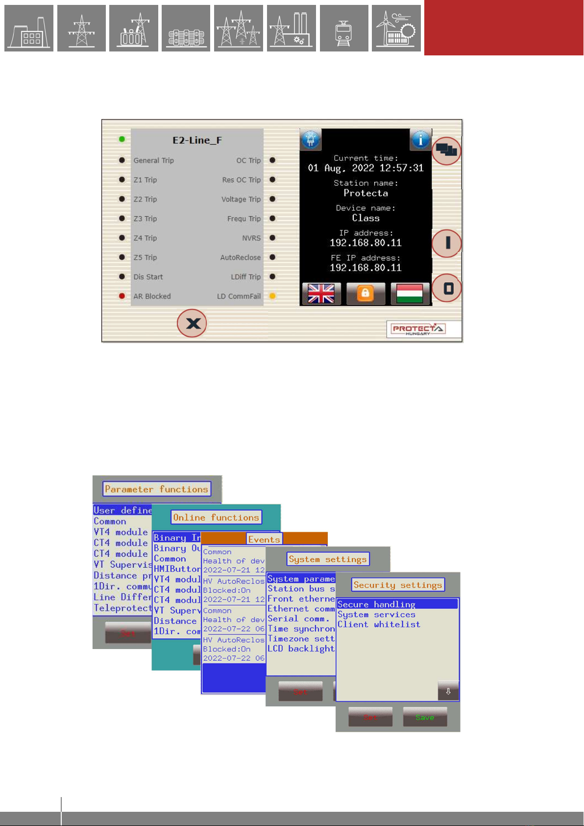
The home screen of the local LCD together with the red marked “Change screen button” and
the “Operation buttons” is shown in the picture below.
Change screen button - This hardware button changes the currently displayed screen for the
subsequent one. The available screens and the order in which they appear by default are: the
home screen, parameters, online functions, events, system settings, security settings and the
custom screens which can be added by the user with the help of the EuroCAP software. The
order can be changed in the LCD editor of the EuroCAP configuration tool. When pressing the
“Change screen button” – as an example – the windows shown in Figure 3-3 belowError!
Reference source not found. can be seen and applied one-by-one, cyclically.
Figure 3-3 Default menu screens (excluding the home screen) displayed on the LCD
Change
screen
button
Operation
buttons
LED reset
button
Figure 3-2 The device face showing the home screen

10
LOCAL OPERATION ON
THE FRONT PANEL
EuroProt+ Operating Manual with Troubleshooting Guide FW version 2.10
www.protecta.hu
Touch the navigation icons or the displayed text lines to perform any actions via the LCD screen.
Operation buttons - These buttons can be used to define certain functions on customer-defined
windows. For example, the user can set up these buttons to turn on/off a circuit breaker or
increment/decrement the position of the tap changer of a transformer. For more information,
please refer to the User-defined/Custom screen section.
LED reset button – Pressing this button removes the latches from all active LEDs and resets
them. Apart from an LED reset, this button can also perform other tasks depending on the relay
configuration. Use of this button, as well as other HMI buttons can be changed using EuroCAP
configuration tool by programming the outputs of the HMI buttons function block from the logic
editor. For more details, see the respective manuals.
11
LOCAL OPERATION ON
THE FRONT PANEL
EuroProt+ Operating Manual with Troubleshooting Guide FW version 2.10
www.protecta.hu
3.3 Using the HMI touchscreen buttons
The touchscreen is the main control area where the user will enable functions and input values
by touching the screen. The touchscreen can be also remotely accessed and controlled through
the web interface (for more information see the corresponding sections in the remote user
interface).
3.3.1 The home screen
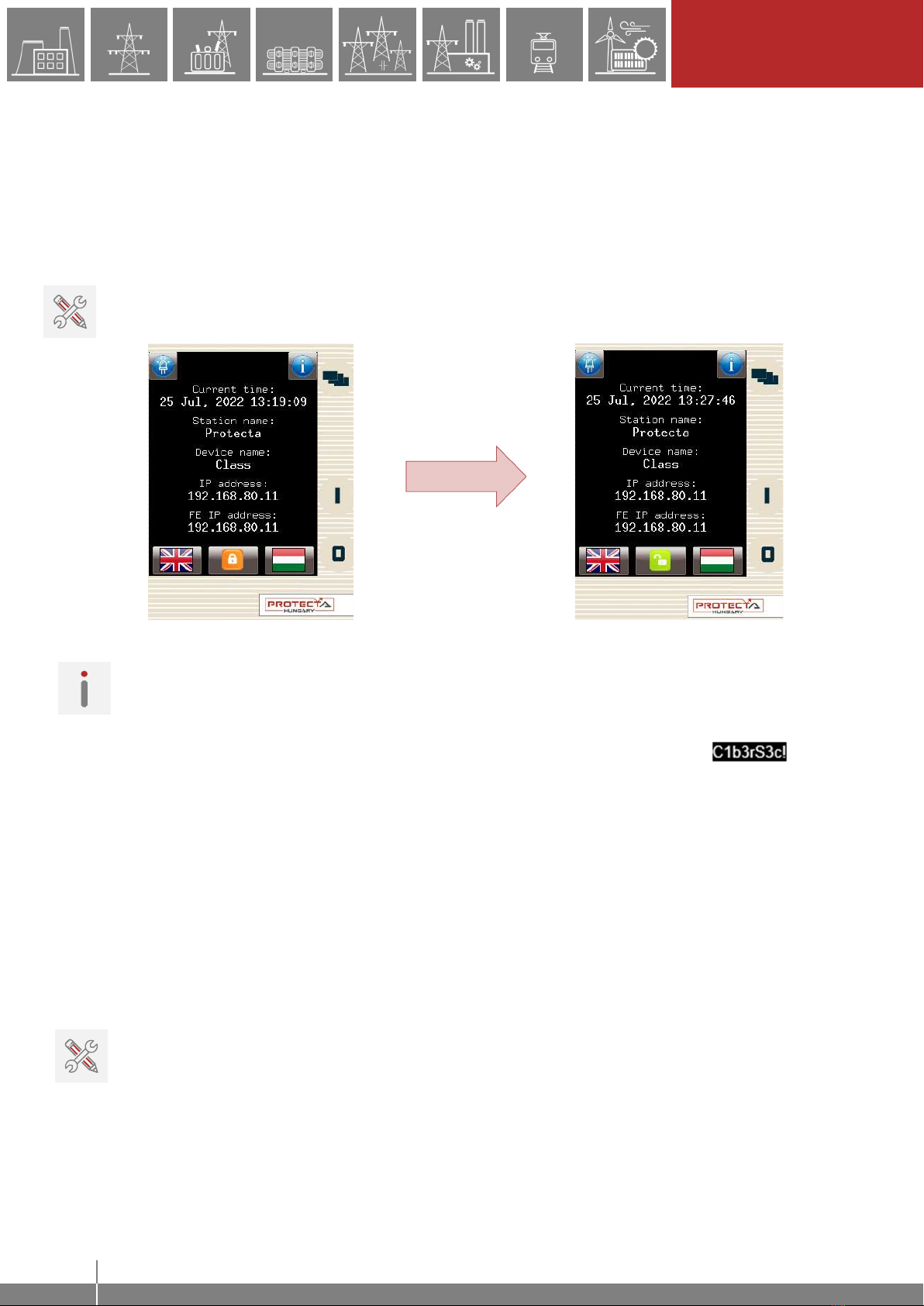
Lock icon – Touching this icon unlocks the device LCD interface, allowing a user to access
various menu items in the device with specific privileges e.g. view settings, view data, manage
settings, etc.
Figure 3-4 Unlocking the device LCD, notice the change in the “lock” icon
NOTE: The device is initially configured with the “Guest” user with all the privileges. As a result
the user doesn’t need to unlock the screen to access all the functions. However, if the “Guest”
rights are limited, the user will need to unlock the screen by logging in in order to access some
privileges.
The device is also initially configured with an “Admin” user with a default password .
Unlock the device with these credentials if the accessibility of the device is limited. See paragraph
4.2.10.2 for more details on user management.
Default/secondary languages (optional) - If available, the user can change the language of the
device by pressing the corresponding flag. With this, the language will change (provided that the
translations exist) on the following objects:
remote web interface
all menu points
newly generated events
newly created disturbance records
device messages (e.g. command confirmation)
NOTE: if the language is changed by using the button on the web interface (see Paragraph 4.2.1),
it will change on the web interface only; the other parts from the list above will remain as they
were set here.
12
LOCAL OPERATION ON
THE FRONT PANEL
EuroProt+ Operating Manual with Troubleshooting Guide FW version 2.10
www.protecta.hu
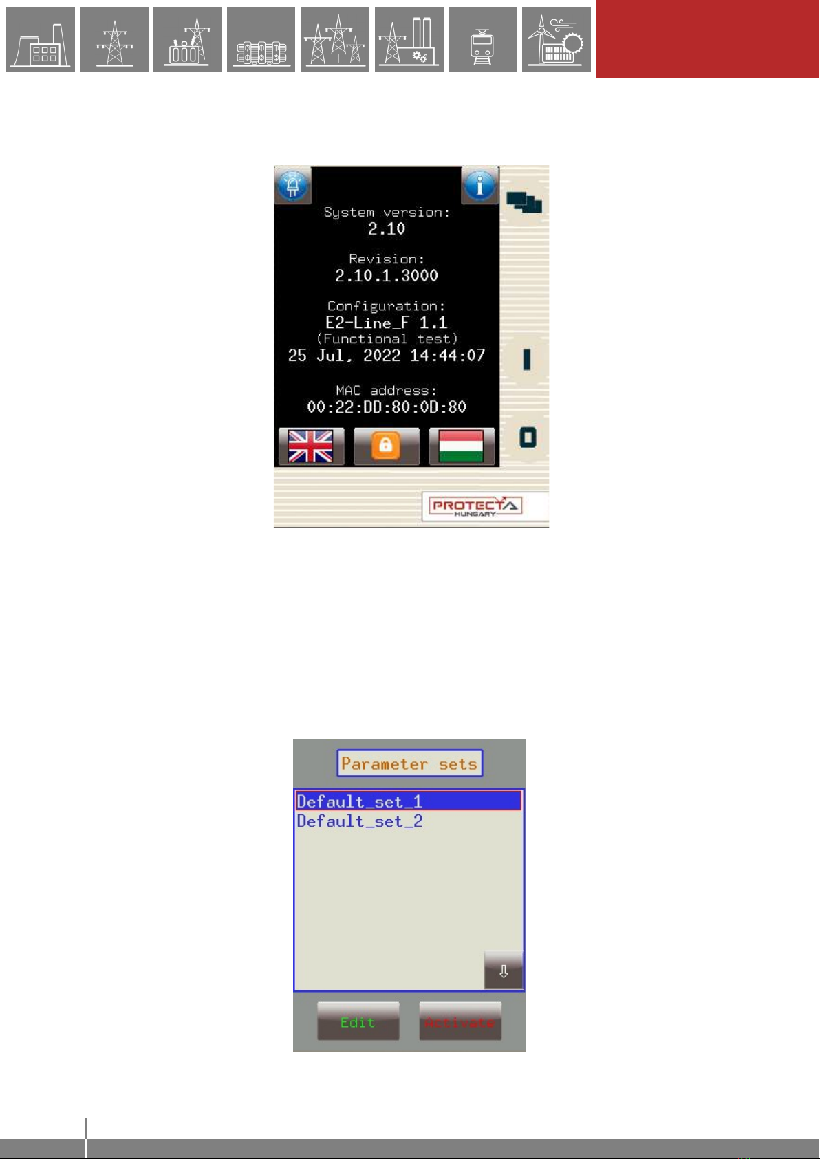
Information and LED buttons – By pressing the “i” button located on the top right corner of the
home screen, additional information is displayed as shown in Figure 3-5Error! Reference source
not found.. The LED icon on the top left corner starts the front panel LED test (see Paragraph
4.2.11.2).
Figure 3-5 Additional information on the home screen
3.3.2 The parameters menu
In this screen, the user can view, set and edit certain parameters within the device. The user can
also choose which parameter set the device should use; this is done with the “Activate” button.
The currently active parameter set has a red box around it (first set in the picture below).
In order to edit or activate a parameter set, touch its name first to select it: it will be highlighted in
blue. Then touch the "Edit" or "Activate" button accordingly.

13
LOCAL OPERATION ON
THE FRONT PANEL
EuroProt+ Operating Manual with Troubleshooting Guide FW version 2.10
www.protecta.hu
Figure 3-6 Parameter sets
Activate button - Activates the selected parameter set so the device will use those values. The
activated parameter set will have a red box around it. Only devices configured with multiple
parameter sets have an activate button.
NOTE: if the parameterset change has a condition configured to it, the activation button will
disappear. In this case, activation of the parameter sets is defined in the device configuration (e.g.
binary input or software switch).
Edit button - This button takes the user to another screen listing the available function blocks
(FBs).
The screen in Figure 3-6 will only appear if there are more than one parameter sets. Otherwise,
the user is immediately taken to the function blocks. Normally, the various function blocks appear
in blue. In case someone has changed a certain value within a given function block, the name of
the function block in this menu item will turn red to notify the user. Within function blocks, the
values of the parameters are normally green, but if they have been modified, they will also turn
red. As an example, change the VT4 voltage type from 200V to 100V as follows:
“Set” function block “Set” parameter “Ok” for new value
“Back” to FB “Back” to save data “Yes” to confirm changes
Figure 3-7 Changing VT4 module Type
IMPORTANT! In order to finalize all changes, the user has to go back to the screen where all the
function blocks are listed and save the changes as shown above.
Also, make sure that while someone is modifying the parameters in the LCD touchscreen, no one
else is doing so on the web interface since this could lead to confusion as to what the values of a
parameter set are.

14
LOCAL OPERATION ON
THE FRONT PANEL
EuroProt+ Operating Manual with Troubleshooting Guide FW version 2.10
www.protecta.hu
Other parameters can be modified similarly to the previously described VT4 voltage type. The
following parameter types are available in the function blocks:
Integer or timer - This is a whole number, and it can be entered with the help of the number pad.
Floating-point number - This is a number that has a decimal point. This can also be input through
the number pad.
List item - A list is displayed with all the possible choices. In this case the user simply needs to
select the desired one (e.g. VT4 voltage type).
Checkbox - The user has the option of enabling or disabling the parameter.
3.3.3 On-line functions, Events, System settings
These menu items have the same content as described in chapter 4. System settings can be
modified similarly to the parameters in paragraph 3.3.2.
3.3.4 User-defined/Custom screens
It is possible to add screens based on the user's needs with the help of the EuroCAP software.
The operation buttons can also be set up to perform certain functions. An example can be seen
using a Single Line Diagram on the following page.
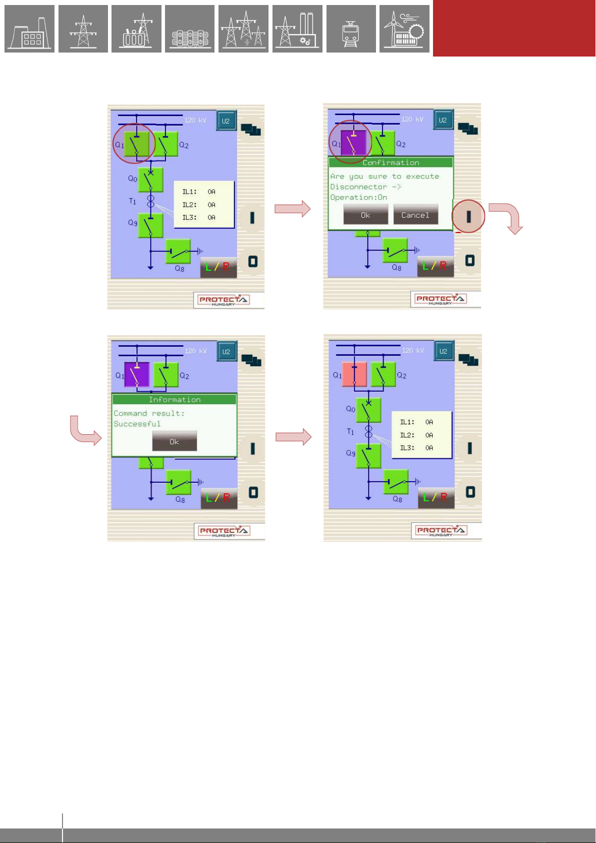
Consider a network represented by the SLD below and we have set up the required operational
buttons to function as "on"/"off". To switch "on" the busbar disconnector Q1:
1. Touch the disconnector “Q1” icon on the touchscreen.
2. The selected object is highlighted and starts blinking. Some action must be performed
with the chosen object; otherwise the selection times out after a short period.
3. So, while blinking, press the "I" button, which has been configured to be the "on" button
when the Q1 object is highlighted.
4. A dialogue box pops up for confirmation of this operation. Again, a limited time is available
for confirmation, otherwise the requested operation is canceled. Press “Ok” to confirm.
5. Another dialogue box pops up stating that the operation was successful. Press “Ok”.
6. The scheme is updated accordingly, with the Q1 line disconnector in the "on" position.
Note again that this behavior was only an example; it may vary according to the configuration of
the actual device.
15
LOCAL OPERATION ON
THE FRONT PANEL
EuroProt+ Operating Manual with Troubleshooting Guide FW version 2.10
www.protecta.hu
Figure 3-8 Closing Q1 disconnector
This screen is updated in real time. A change in any sort of state or any parameter that is set up
to be measured, will be shown and updated accordingly.
If there is an error with the operation (e.g. block by interlocking), the device will notify the user
with another another dialogue box popping up with the reason for the error.
1 2
3
4
5
6

16
REMOTE OPERATION VIA
WEB BROWSER
EuroProt+ Operating Manual with Troubleshooting Guide FW version 2.10
www.protecta.hu
4 Remote operation via web browser
A web browser and an Ethernet connection are needed in order to access the device interface.
HTML5 compatible web browser is recommended. To properly display the data on the screen, it
is recommended to have a screen resolution of at least 1024x768. The latest version of the
following web browsers can be used:
• Mozilla Firefox
• Apple Safari
• Google Chrome
• Microsoft Edge
JavaScript must also be enabled in your browser. For security reasons, the device allows only
limited number of connections over the network (a maximum of 10 is guaranteed).
4.1 Properties of the Ethernet communication
The built-in 5-port Ethernet switch allows EuroProt+ to be connected to IP/Ethernet based
networks. The following Ethernet ports are available in general:
On the front panel of the device:
RJ-45 Ethernet or EOB (Ethernet over Board) user interface
On the rear side of the CPU unit:
Station Bus (100Base-FX Ethernet)
Redundant Station Bus which can be:
o 100Base-FX Ethernet, or
o 10/100Base-T port via RJ-45 (only one can be active of these two)
Process bus (100Base-FX Ethernet)
The different HMI and CPU types are utilizing different ports. Further information about the
available ports and the applied interfaces on various HMI and CPU types can be found in the
“Hardware description” document.
The embedded web-server supports the following actions:
Modifying user parameters
Managing the event list and disturbance records
Managing passwords
Online displaying measured data and generated binary information
Performing commands
Firmware update
Performing other administrative tasks
User management and security settings
4.1.1 The Ethernet connection
There are several ways to be connected to an Ethernet network. The availability of the below
listed connection types depends on the device hardware configuration.
4.1.1.1 Using the RJ-45 connection
RJ-45 connector is available on the front panel if no EOB is selected for the configuration. In
addition, many CPU types also utilize an RJ-45 connector, which is located on the rear side of
the device on the CPU card. Using an UTP cable with RJ-45 connector at both ends, the device
can be connected directly to a computer or an ethernet switch.

17
REMOTE OPERATION VIA
WEB BROWSER
EuroProt+ Operating Manual with Troubleshooting Guide FW version 2.10
www.protecta.hu
4.1.1.2 Using the EOB connection
EOB connection is available on the front panel if no RJ-45 connector is selected for the
configuration. Attach the magnetic EOB connector to the front panel of the device (see Figure
3-1). The magnets assure the correct position of the adapter. Connect the other two ends of the
cable to the RJ-45 connector and to the USB port of a computer. The special cable with magnetic
connector on one end and RJ-45+USB connectors on the other end shall be ordered from
Protecta.
4.1.1.3 Using fiber optic connections
The different types of fiber optic interfaces for 100Base-FX Ethernet provides connection to an
Ethernet switch with identical fiber optic inputs. Using this connections all IED-s on the network
with client functionalities, e.g. a computer, has access to the device. For more details about the
fiber optic connector types see the CPU and COM module sections in the “Hardware
description”.
4.1.2 Settings needed for the Ethernet connection
The web interface of the EuroProt+ devices can be accessed over Ethernet based protocols only.
Therefore, it is extremely important to set up the network before accessing the device.
Typically, the rear ports are connected to the substation network. The front port is ideal for
management or troubleshooting. Station bus settings and front ethernet settings can be defined
separately.
To connect the device to a station or corporate network, contact the system administrator for
available IP address, gateway address, net-mask, DNS and NTP server addresses.
The user can also connect directly to the device via Ethernet protocol. In the following guidance,
we assume that the user connects directly to the device via computer without the presence of any
active network component (e.g.: switch, router).
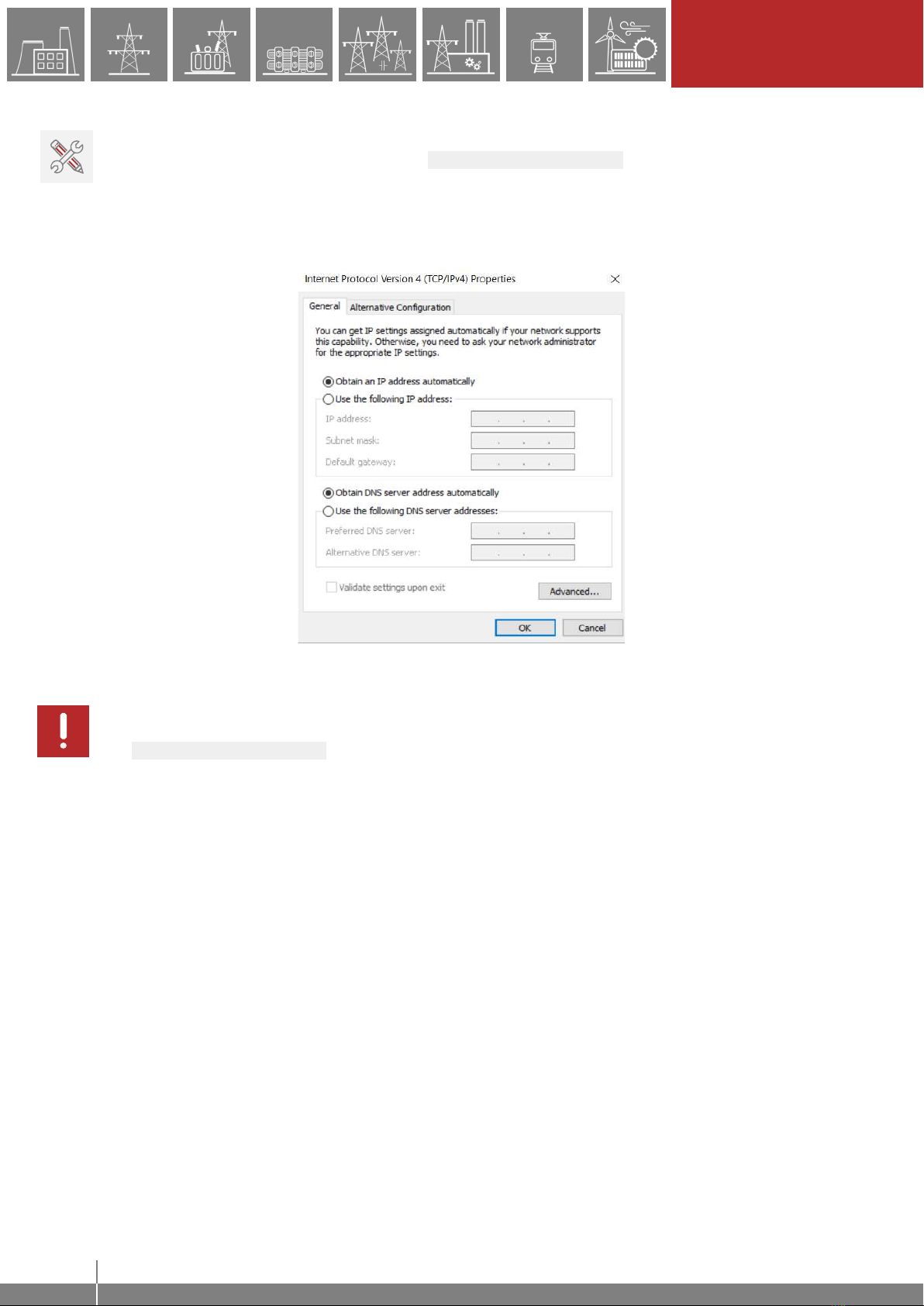
4.1.2.1 Connection to the device with fix IP address
The device uses fix IPv4 address range and the user is allowed to modify the address. User’s
computer must be set with fix IP address and netmask according to the used IP address range
and netmask in the device.
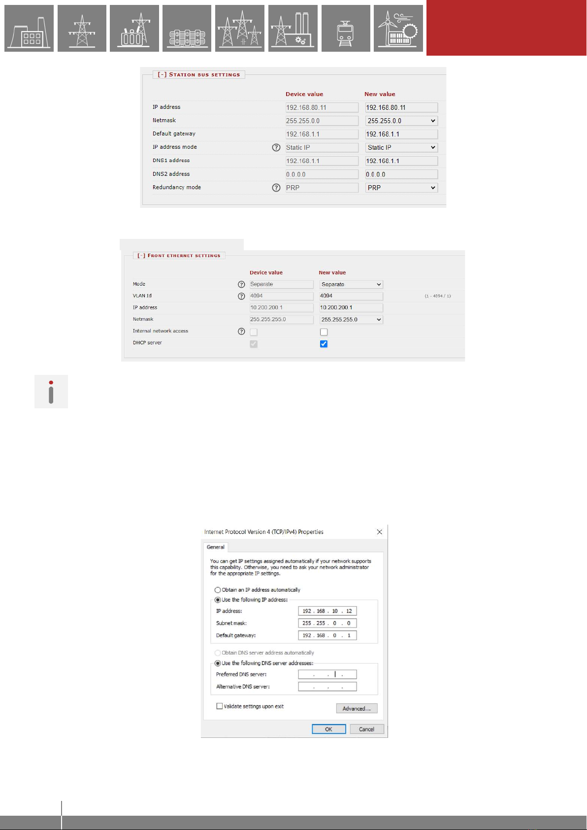
Settings of the device:
The initial IP addresses of the device can be read from the home page of the LCD. If connected
via the rear ports, use the displayed “IP address”. If connected via the front ethernet port, use the
displayed “FE IP address”. The default netmask for the rear IP address is 255.255.0.0 while for
the front IP address is 255.255.255.0.
After the initial setup, the IP address settings can be changed from the System settings ->
Station bus settings menu for the rear ports and System settings -> Front ethernet
settings for the front port.
The screenshot below shows sample Station bus settings:
18
REMOTE OPERATION VIA
WEB BROWSER
EuroProt+ Operating Manual with Troubleshooting Guide FW version 2.10
www.protecta.hu
Figure 4-1 Sample station bus settings in the device
Sample Front ethernet settings are shown below:
Figure 4-2 Sample front ethernet settings in the device
NOTE: This illustration assumes that the front ethernet is “Separated” from the station bus.
Otherwise, same IP settings as the station bus settings are used.
Settings of the user's computer (with fix IP address):
Connection to the station bus
The possible IP settings of the user’s computer according to the sample device settings above:
IP address: in range from 192.168.0.1 to 192.168.254.254*
Netmask: 255.255.0.0
Default gateway:192.168.0.1
*Note: the IP address must differ from that of the device
Figure 4-3 An example of settings in the user’s computer with fix IP address
19
REMOTE OPERATION VIA
WEB BROWSER
EuroProt+ Operating Manual with Troubleshooting Guide FW version 2.10
www.protecta.hu
Connection to the front ethernet
The front ethernet port has an embedded DHCP server. To connect the PC, enable DHCP by
checking the “DHCP server” box under the Front ethernet settings tab as shown in Figure
4-2 above. Secondly, use automatic IP settings in the PC network settings. See Figure
4-4Error! Reference source not found. below.
Figure 4-4 Possible settings in the user’s computer with DHCP server
IMPORTANT: Caution shoud be taken if the front ethernet port has to be connected to the
corporate network. In these cases, as a safe practice, uncheck the “DHCP server” box in the
Front ethernet settings tab, otherwise the device could act as a new DHCP server in the
network.
4.1.3 Using web browsers
First the user must check if the browser is accessing the device via proxy-server. If there is a
proxy-server in the network, the system administrator shall be contacted in order to get access.
If this is clarified, the user can type the IP address of the device into the browser’s address bar.
(The IP address can be read from the home screen of the local LCDError! Reference source
not found..) After that the usual procedures of web browsing shall be followed.
20
REMOTE OPERATION VIA
WEB BROWSER
EuroProt+ Operating Manual with Troubleshooting Guide FW version 2.10
www.protecta.hu
4.2 Menu items in the web browser
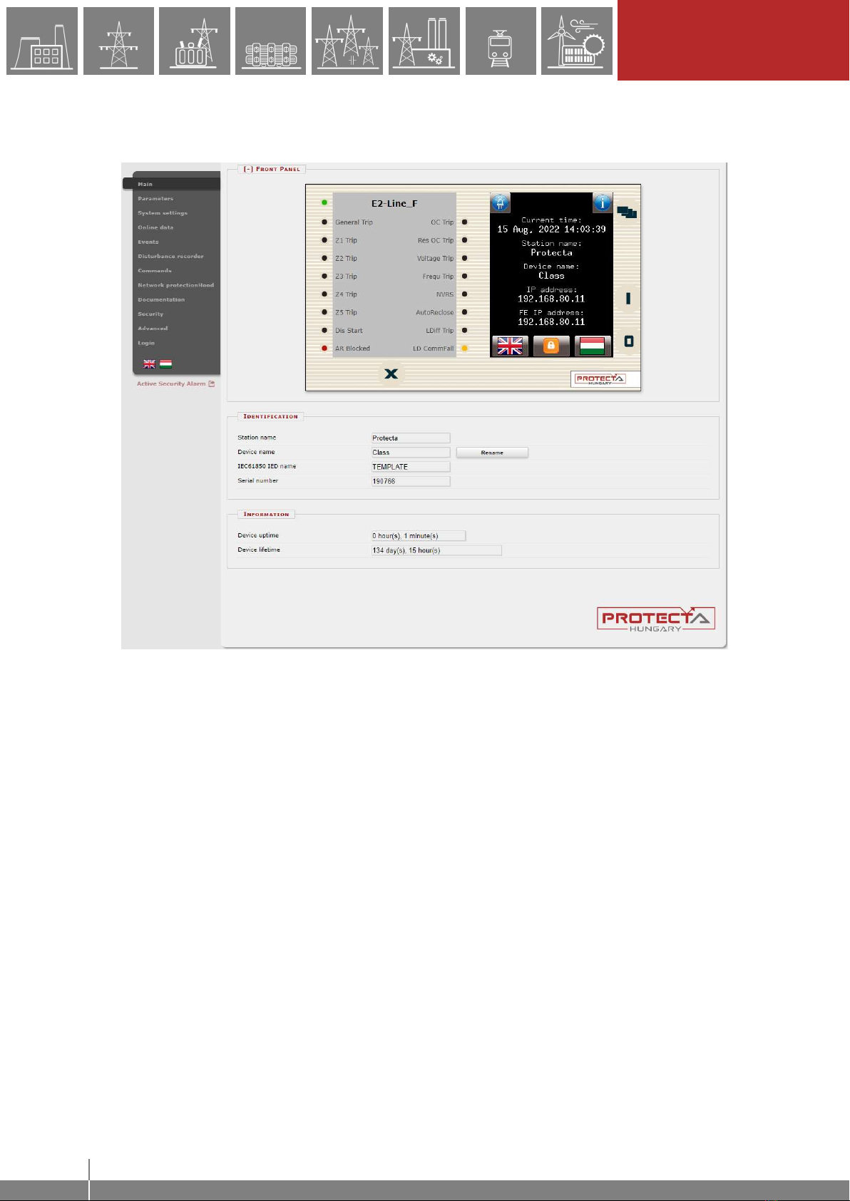
4.2.1 Main panel
Figure 4-5 Main menu
The front panel of the device can be controlled from here (Figure 4-5). The image in the center of
the screen acts/responds in the same way as the touch screen and the LEDs, except the on (1)
and the off (0) buttons. These two buttons are inactive for security reasons.
The X button on the bottom of the front panel picture initiates a LED reset. LED description text
is determined by the configuration and may be different than the actual label inserted in the device
front panel.
Identification - User can change the station and device names from this panel by typing in
the new values and clicking on the Rename button. IEC61850 IED name is only for display
here but can be edited in the EuroCAP tool if needed.
Information part - There are two fields for measuring device operating time. Uptime field
displays the time elapsed from the last power on of the device. Device lifetime field value
equals the number of days of the device's energized state. In case of a CDSP update, the
device uptime disappears and RDSP/CDSP uptime appear.
The language button (if present) under the menus changes the displayed language on the
webpage only. This means that the menus (parameters, settings etc.) will be shown in the chosen
language, but the events and disturbance records will still be generated on the language set on
the main local LCD screen (see Paragraph 3.3.1 for details)
Other manuals for EuroProt+
3
Table of contents


