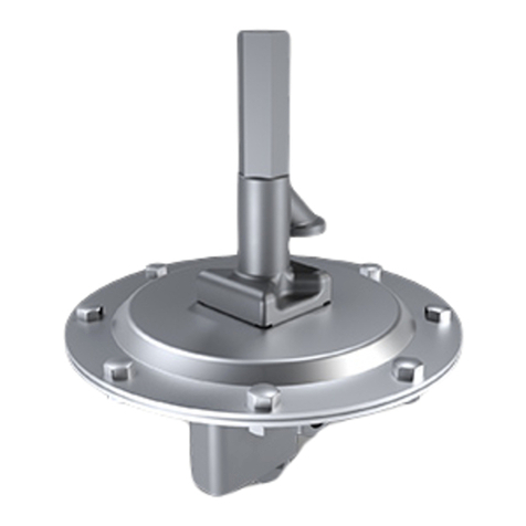
Protectoseal 7800 Series Maintenance and service guide

SERIES 7800
End- f-Line Emergency Pressure Vent
NOTE 1: This vent style includes a removable weatherhood.
The hood stem guide may be taped to the top of the
hood to prevent damage during shipment. This stem
guide will be threaded into the tapped hole on top of
the hood.
NOTE 2: hen pressure weights (packed separately if
heavy) are included with a unit, the weights should
be inspected, properly identified and set aside for
later installation. eights will be stamped with a se-
rial number matching the number on the vent; identi-
fication as pressure or vacuum weights; and a
statement as to the contribution that each weight
provides to the total pressure setting.
INSTALLATION PROCEDURE:
1. Loosen wing nuts and remove weatherhood.
2. ithdraw pressure pallet assembly. Remove and discard
protective cardboard and tape from assembly. The card-
board protects the diaphragm during shipment.
3. Remove protective flange cover.
4. Check carefully to insure that all packing materials are re-
moved from on or inside the vent housing and from the
pallet assembly.
5. Mount the vent to the appropriate tank flange using gas-
kets compatible with service conditions. Note: For some
vent styles, threaded studs that mate with tapped holes
in the vent housing flange are provided. For best perform-
ance, the vent should be mounted level so that the seat-
ing surfaces are no more than 1° off horizontal.
6. Reinstall the pressure pallet assembly. Setting weights (if
provided) should be installed by engaging the hole in the
weight on the pallet assembly stem. Make sure that
weights are properly installed as marked to provide spec-
ified set points. Heavy weights may be provided with
tapped holes to temporarily attach lifting hardware to fa-
cilitate installation. Any such threaded fasteners used
during installation must be removed from the weights.
Foreign objects will limit the lift capability of the pallet as-
semblies and will reduce rated flow capacity of the vent.
7. Replace the weatherhood. Note: Make sure that the
pressure pallet assembly stem positively engages the
hole in the stem guide in the weatherhood. It may be use-
ful to verify engagement of the pressure stem into the
weatherhood guide by unthreading the guide and then re-
installing it with the stem centered in the hole. The pallet
assembly must be free to move upwards, with the pallet
stem traveling into the stem guide.
8. Secure hood with wing nuts.
www.protectoseal.com
PROTECTOSEAL®
CAUTION:
If any questions arise concernin the proper installation
or maintenance of our products, please contact
Protectoseal or one of our Authorized Representatives.
When installin any Protectoseal device, the
le al, corporate and advisory safety re ulations and
procedures appropriate for the specific installation site
must be fully understood and followed.

Vent Line / In-Line Parallel Plate
Fla e Arrester is designed for
installation in open vent pipe or
bleed lines fro storage or pro-
cessing tanks. Suitable for NEC
Group D (IEC Group IIA) vapors
Co bination Pressure / Vacuu
Relief Vent & Fla e Arrester
provides pressure and vacuu
relief as well as protection fro
propagation of externally intro-
duced fla es. Suitable for NEC
Group D (IEC Group IIA) vapors.
Series 4950 Series 830
Pipe-Away Pressure Vacuu
Relief Vent for applications that
require hazardous vapors be
processed into anifolded
piping and not released into the
at osphere
Series 18540
Ins alla ion & Main enance Series 7800
End-of-Line Emer ency Pressure Vent
ADDITIONAL PRODUCTS FROM PROTECTOSEAL
©2009 The Protectoseal Company VM-7800/1
PROTECTOSEAL®
Safety Without Compromise
225 Foster Ave., Bensenville, IL 60106-1690
P630.595.0800 F630.595.8059
[email protected] www.protectoseal.com
MAINTENANCE:
Protectoseal recommends that our products be inspected and
maintained according to the normal maintenance schedule of
the facility. At a minimum, maintenance should be conducted
annually. More frequent maintenance may be required, and
should be scheduled, for unusual service conditions.
CAUTION: When maintaining any Pr tect seal
device, the legal, c rp rate and advis ry safety
regulati ns and pr cedures appr priate f r the
specific installati n site must be fully underst d
and f ll wed.
CAUTION: Tank vap r space pressure r vacuum
sh uld be relieved bef re any maintenance
perati ns are undertaken.
MAINTENANCE PROCEDURE:
1. Loosen wing nuts and remove weatherhood.
2. Remove any loose dirt or foreign material from the hous-
ing interior and exterior. Check inside the stem guide hole
of the cover and remove any dirt or accumulation of for-
eign material.
3. ithdraw the pressure pallet assembly and any weights.
Set aside for inspection. Note: Identify any weights on
the pressure pallet assembly for later reinstallation.
4. Inspect the screen that protects the pressure port. Clean
or replace as necessary.
5. Inspect and clean the machined seating surface in the
vent with a suitable cleaning fluid. Seat should be free of
nicks, mars or accumulation of foreign material.
CAUTION: D n t use a file r ther sharp t l
t clean the seating surface.
6. Inspect the pallet assembly. If pallet is deteriorated or
bent, it must be replaced. Inspect the diaphragm material
in the pallet assembly. The diaphragm must be clean, flat
and smooth. If the diaphragm material is deteriorated, it
must be replaced. Make sure that all nuts and screws on
the pallet assembly are tightened securely.
7. Reinstall the pressure pallet assembly. Setting weights (if
provided) should be installed by engaging the hole in the
weight on the pallet assembly stem. Make sure that
weights are properly installed as marked to provide spec-
ified set points. Heavy weights may be provided with
tapped holes to temporarily attach lifting hardware to fa-
cilitate installation. Any such threaded fasteners used
during installation must be removed from the weights.
Foreign objects will limit the lift capability of the pallet as-
sembly and will reduce rated flow capacity of the vent.
8. Replace the weatherhood. NOTE: Make sure that the
pressure pallet assembly stem positively engage the hole
in the stem guide in the weatherhood and in the weather-
hood. It may be useful to verify engagement of the pres-
sure stem into the weatherhood stem guide by
unthreading the guide and then reinstalling it with the
stem centered in the hole. The pallet assembly must be
free to move upwards, with the pallet stem traveling into
the stem guide.
9. Secure weatherhood with wing nuts.
E ergency Pressure Manhole
Cover Vents provide e ergency
pressure relief for storage
tanks where vacuu relief is
being provided for by a separate
operating vent
Series 53300
888.858.3647 | relevantsolutions.com
Distributed by:
Other Protectoseal Control Unit manuals
Popular Control Unit manuals by other brands

SAFERA
SAFERA PCU6.3-F installation manual
FISNAR
FISNAR VD510-UV instruction manual

Moxa Technologies
Moxa Technologies DA-IRIGB-4DIO-PCI104-EMC4 user manual
Rittal
Rittal DK 7859.212 Assembly, Installation and Operation

Tekmar
Tekmar 423 Wiring Brochure
Honeywell
Honeywell FALCON MJ Pulse/M-Bus operating instructions
