6 Operation with power pack
Active 8-way PSM modules
10
EN
6.1 Connecting further PSM modules
(power pack operation)
A maximum of four modules may be connected in
series. Snap the module into the PSM busbar as
described previously. Insert the RJ45 cable into the
free socket of the first module and the other end in
the RJ45 socket of the new module. During the in-
sertion, ensure that you hear the noticeable clicking
noise of the RJ45 plug.
To remove the plug again, press the latching catch
of the RJ45 plug and pull carefully on the plug.
6.2 Specifying the current limit value
(power pack operation)
You can specify the current limit values for alarms. If
these values are undershot or overshot, the 7-
segment display will flash and show the actual cur-
rent value. The button on the PSM module must be
used to set the current limit values. Please proceed
as follows.
6.2.1Specifying the lower current limit
value (power pack operation)
Press the button for three seconds. An "L" will ap-
pear in the display.
Press the button again for three seconds until the
digit "0" appears in the display.
Press the button briefly to specify the lower alarm
current limit value.
Press the button for three seconds to save the cur-
rent limit value. An "H" will appear in the display.
Wait a few seconds until the display changes in the
status display (actual current value).
6.2.2Specifying the upper current limit
value (power pack operation)
Press the button for three seconds. An "L" will ap-
pear in the display.
Press the button briefly once until an "H" appears in
the display.
Press the button again for three seconds until the
digits "15" appear in the display.
Press the button briefly to specify the upper alarm
current limit value.
Press the button for three seconds to save the cur-
rent limit value. An "A" will appear in the display.
Wait a few seconds until the display changes in the
status display (actual current value).
6.2.3Limit values of the multicolour LED
display
If the PSM module or the PCU is operated with po-
wer pack, the limit values for which the LEDs of the
associated connection change colour cannot be
changed. In this case, the default values are re-
tained.
Default values:
7859.222, 7859.225:
Up to 2 A: green, up to 5 A: orange, above 5 A: red
7859.212, 7859.215, 7859.232, 7859.235:
Up to 3 A: green, up to 10 A: orange, above 10 A:
red
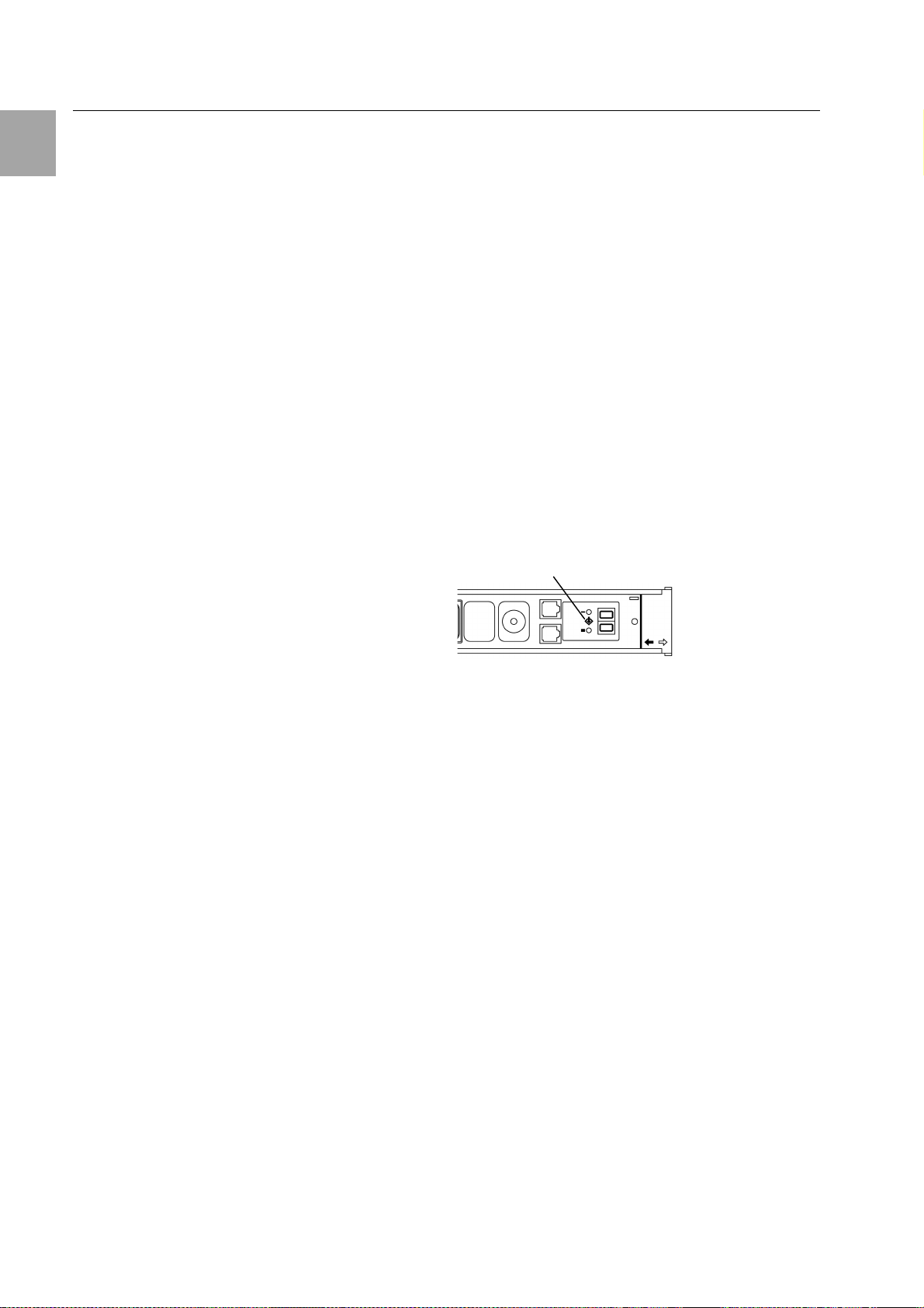
6.3 Assigning PSM module addresses
(power pack operation)
Each module must be assigned an address for both
stand-alone operation and PSM modules switched
in series. Please proceed as follows.
1
Fig. 9 Assign addresses (power pack opera-
tion)
Press the button (1) on the PSM module for three
seconds. An "L" will appear in the display.
Then press the button twice briefly. An "A" will ap-
pear in the display.
Now press the button for three seconds. A "0" will
appear in the display.
Press the button briefly until the address "1" ap-
pears in the display.
Press the button for three seconds to save the ad-
dress. A small rectangle will appear in the display.
Wait a few seconds until the display changes in the
status display (actual current value).
Now assign an address to each module as de-
scribed previously. The second module in the series
receives the address "2", etc.
If a module is connected to a different power pack,
the address begins with "1" again.
6.4 Configuring the display (power
pack operation)
The PSM module has an integrated position sensor.
This is responsible for the correct reading of the
display. The position sensor is activated as factory
setting. This means when the PSM module is turned
in the PSM busbar (to electric circuit 2), the display
is not up but rather down. The display is turned


