© 2009 W 423 - 03/09 10 of 12
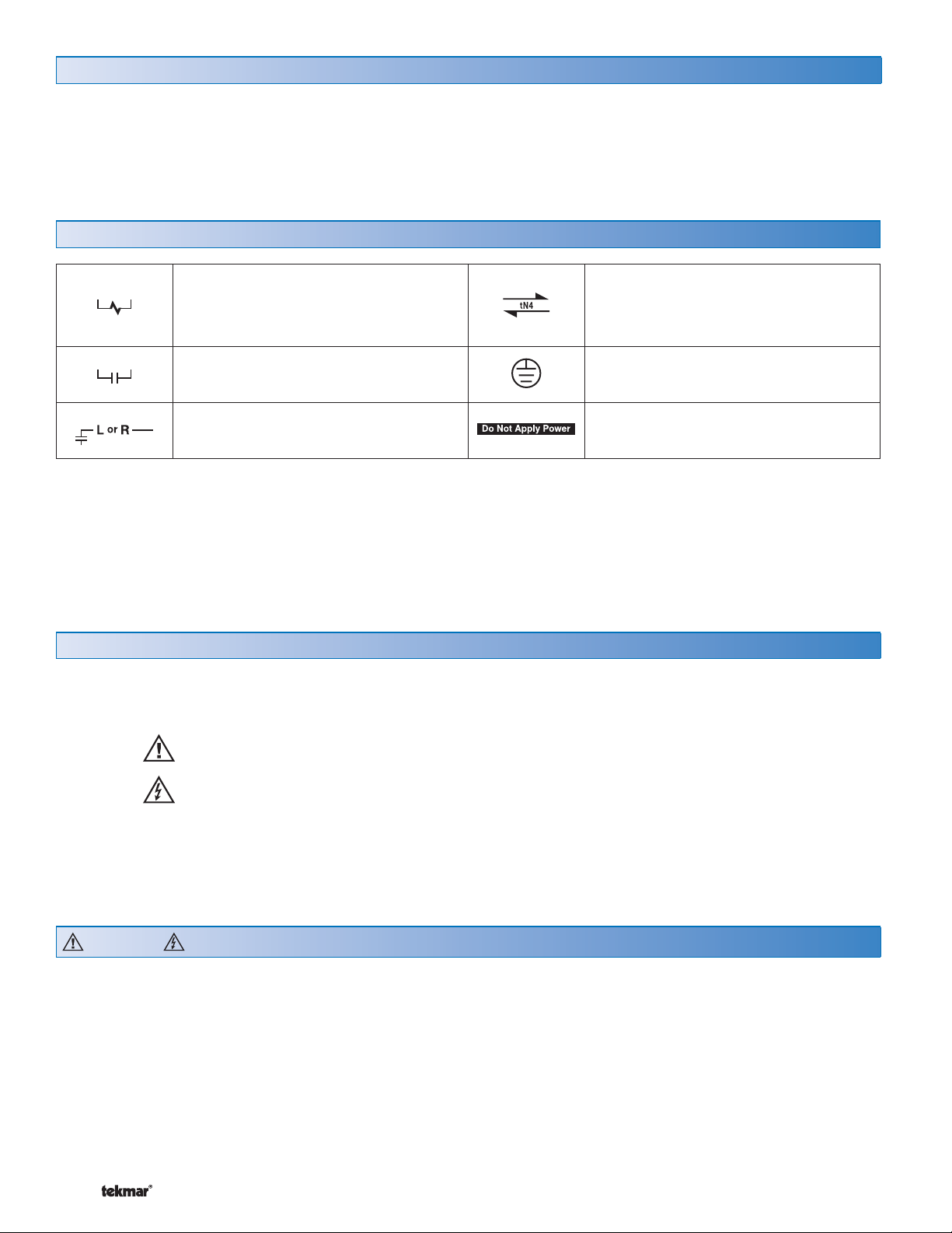
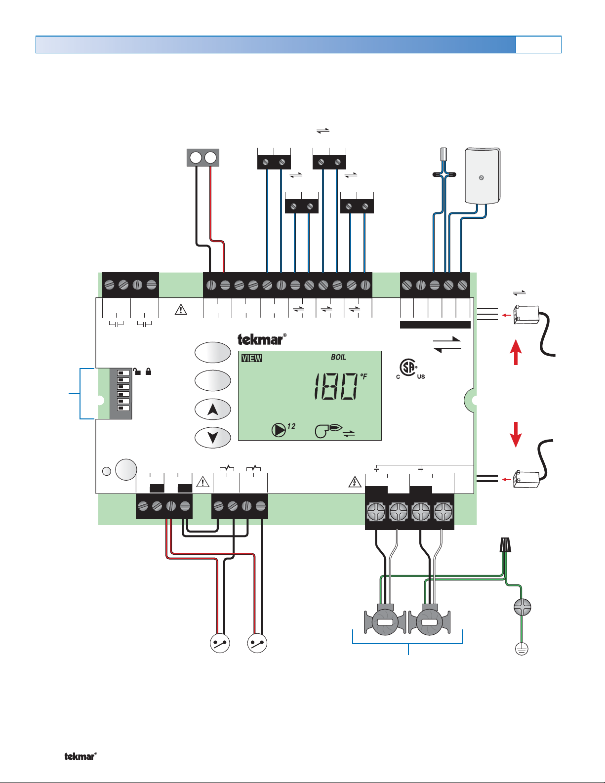
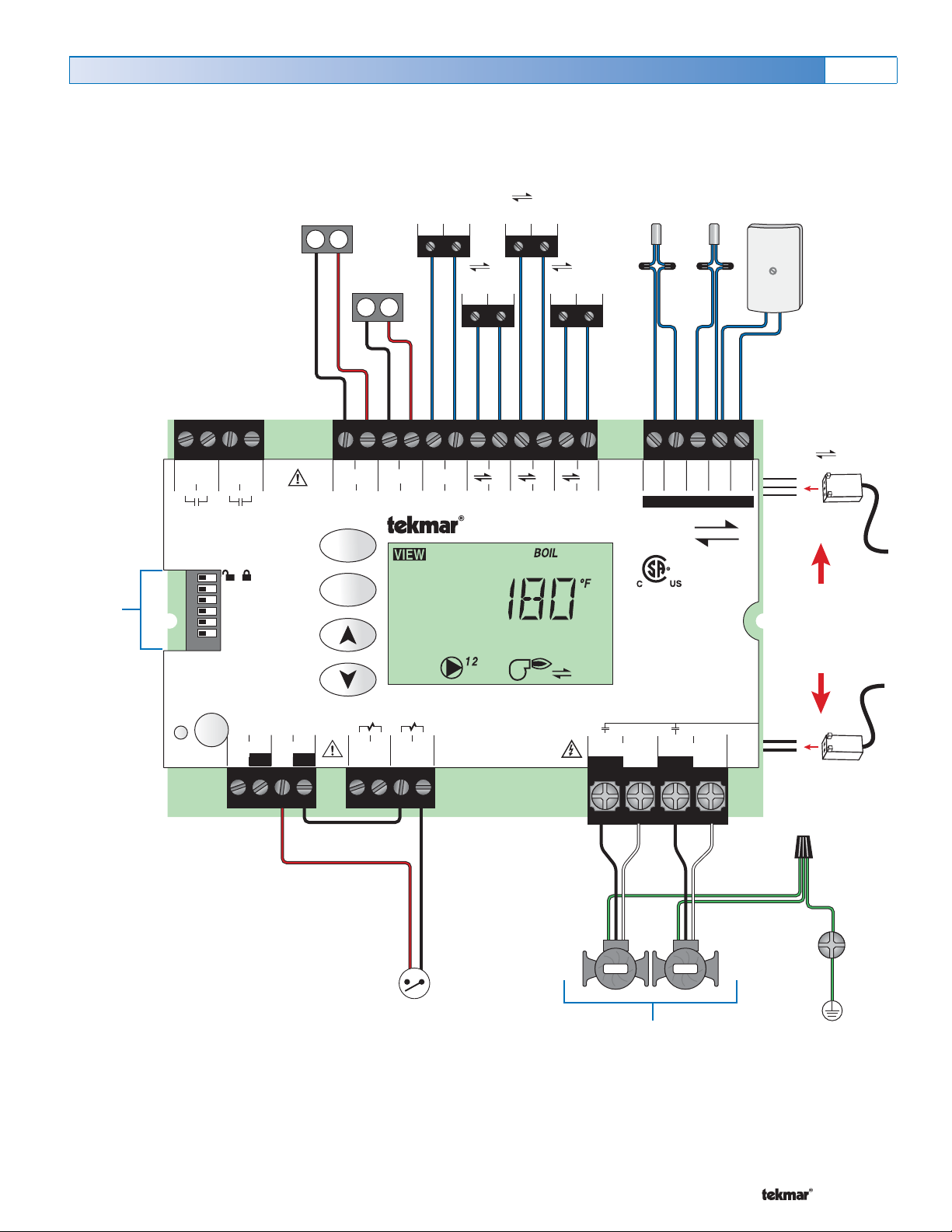
Wiring the DHW and Primary Pump Terminals 79 - 80, 81 - 82
The control operates a Primary Pump, and a DHW
Pump.
• If a Primary Pump is used, the pump is wired directly to
terminals 81 and 82.
• If a DHW Pump is used, the pump is wired directly to
terminals 79 and 80.
• The pumps’ ground wires are connected to the ground
screw provided in the wiring chamber.
Note: For pumps larger than the control’s rated capacity,
an external isolation relay must be used.
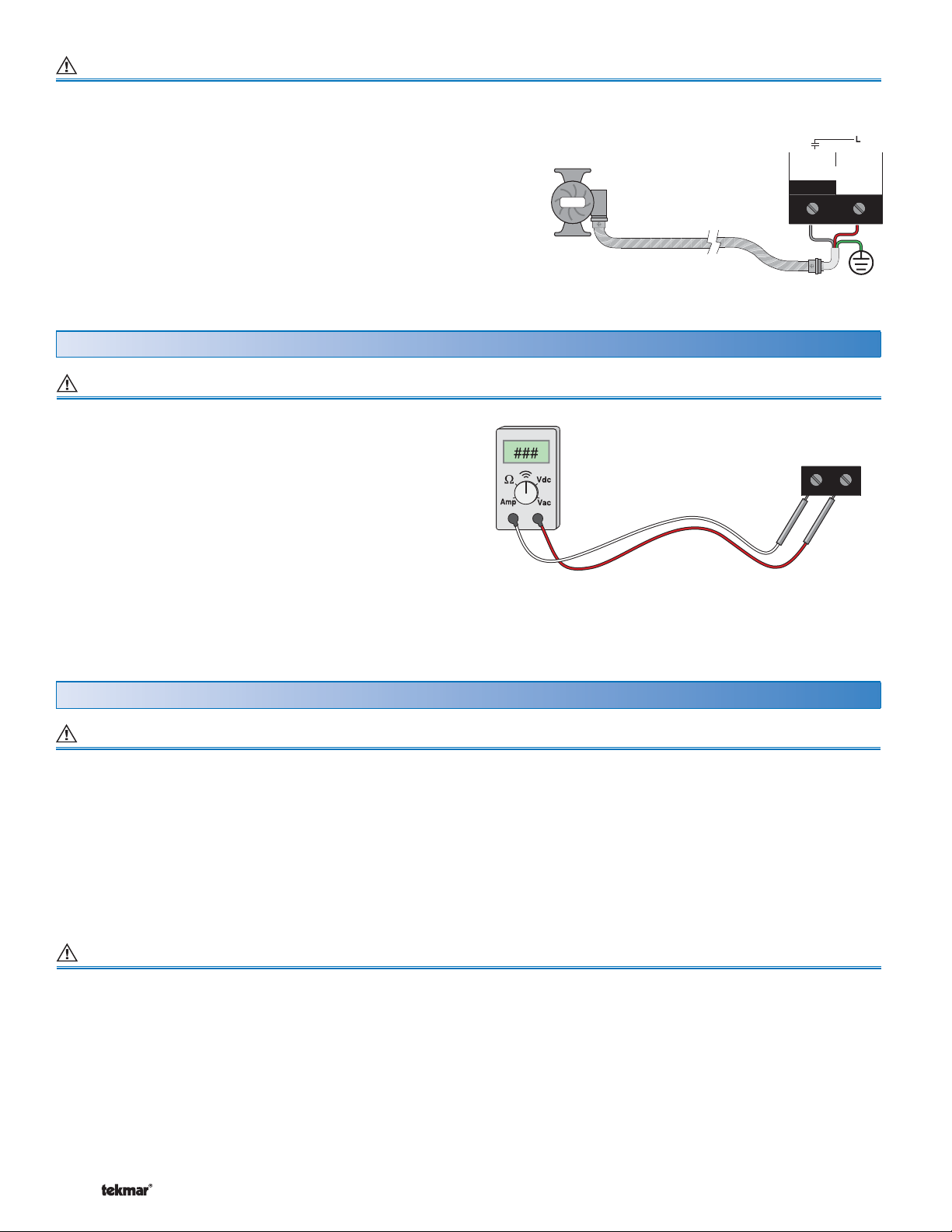
Pump
Pump
L & N
81 82
Primary
Pump N
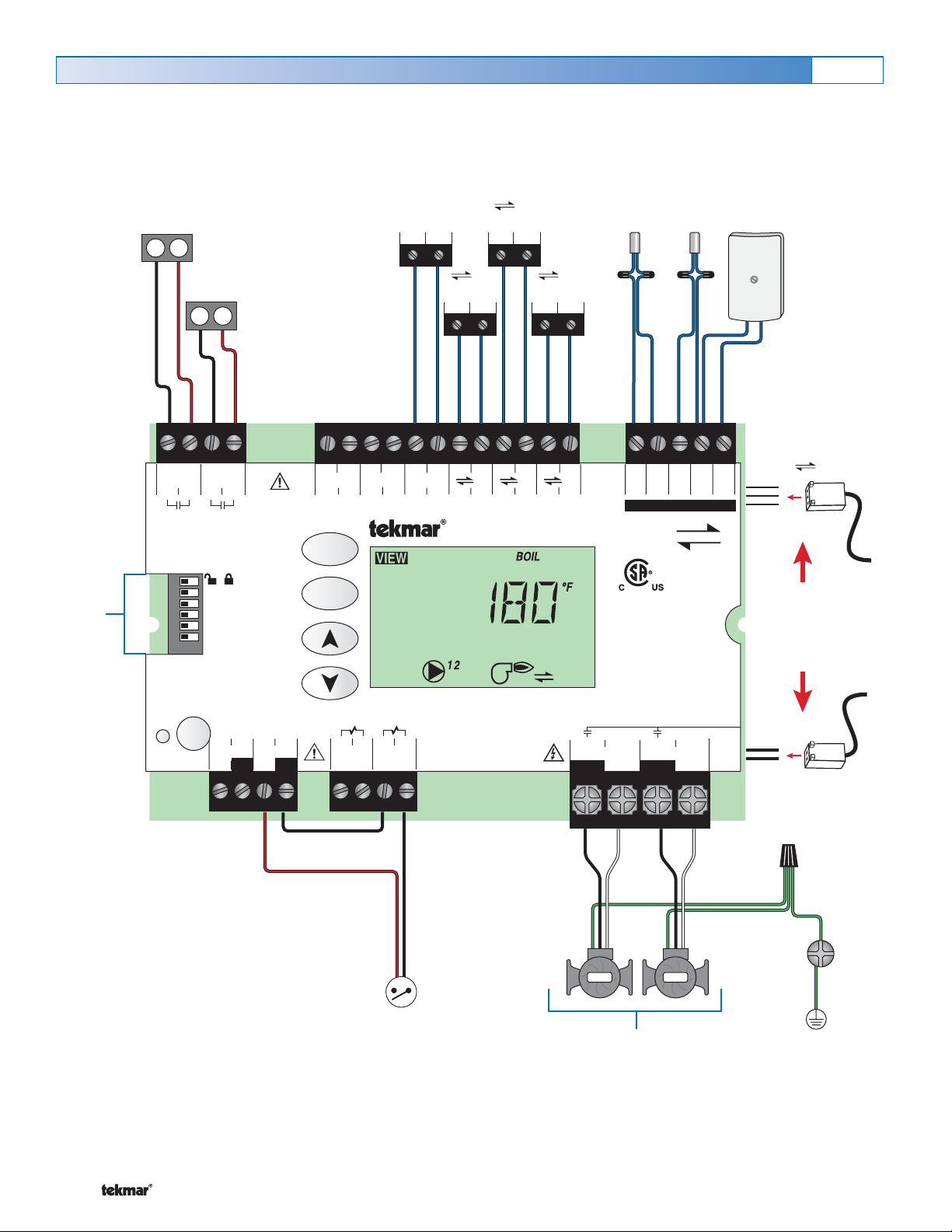
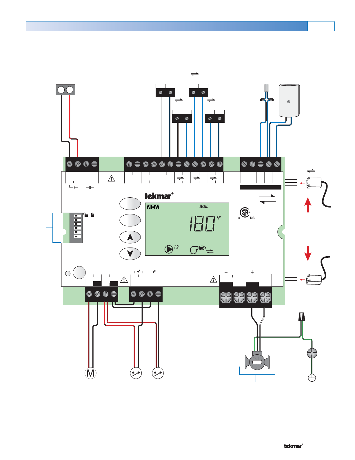
Testing the Control Terminals 50 - 82
Test the Stage 1 and Stage 2 Contacts Terminals 50-53
1. Shut off power to the control and the boiler circuit.
2. Remove the front cover from the control. Disconnect the
wires from the Stage 1 and Stage 2 contacts (terminals
50-51, 52-53).
3. Apply power to the control and press the Test Button.
4. Use an electrical test meter and check for continuity
between terminals 50-51 and 52-53.
• When each stage symbol is displayed in the LCD, there
should be continuity.
• When the stage symbol is not displayed in the LCD,
there should be no continuity.
5. Reconnect the wires to the Stage 1 and Stage 2 contacts
(50-51 and 52-53), install the front cover on the control
and apply power to the boiler circuit.
Testing Modulating Action (0 - 10 V dc) Terminals 54 - 57
1. Ensure that the control is set to operate the modulating
output.
2. Remove the front cover from the control.
3. Press the Test Button.
4. When the % output graph and the burner symbol are
displayed in the LCD, use an electrical test meter to
measure the (dc) voltage between the Mod (dc) + and
the Mod (dc) - terminals (54-55, 56-57). The reading
should vary between 0 V (dc) and 10 V (dc).
5. If power is not present:
• Check the power supply to the Zone Manager and the
field replaceable fuse for the transformer on the Zone
Manager.
• If the fuse is blown, determine the cause of the failure
before replacing the fuse.
• Also check the Plug in connections on the underside of
the control.
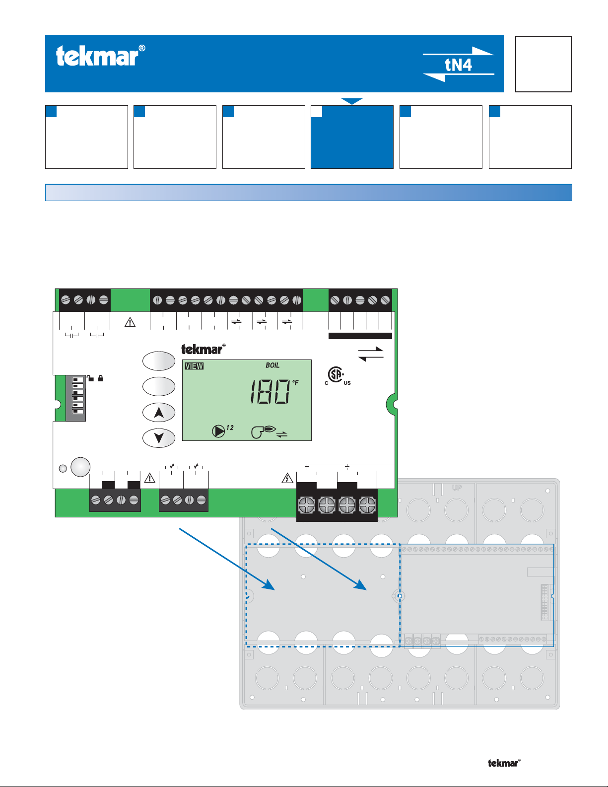
Troubleshooting the Wiring
Test Meter
Control Terminals
The following tests are to be performed using standard
testing practices and procedures and should only be carried
out by properly trained and experienced persons.
A good quality electrical test meter, capable of reading from
at least 0-300 V (ac), 0-30 V (dc), 0-2,000,000 Ohms, and
testing for continuity is essential to properly test the wiring
and sensors.
General
For an explanation on the use of the Test Button, the ‘Test’ sequence or any error messages, refer to the Data Brochure.