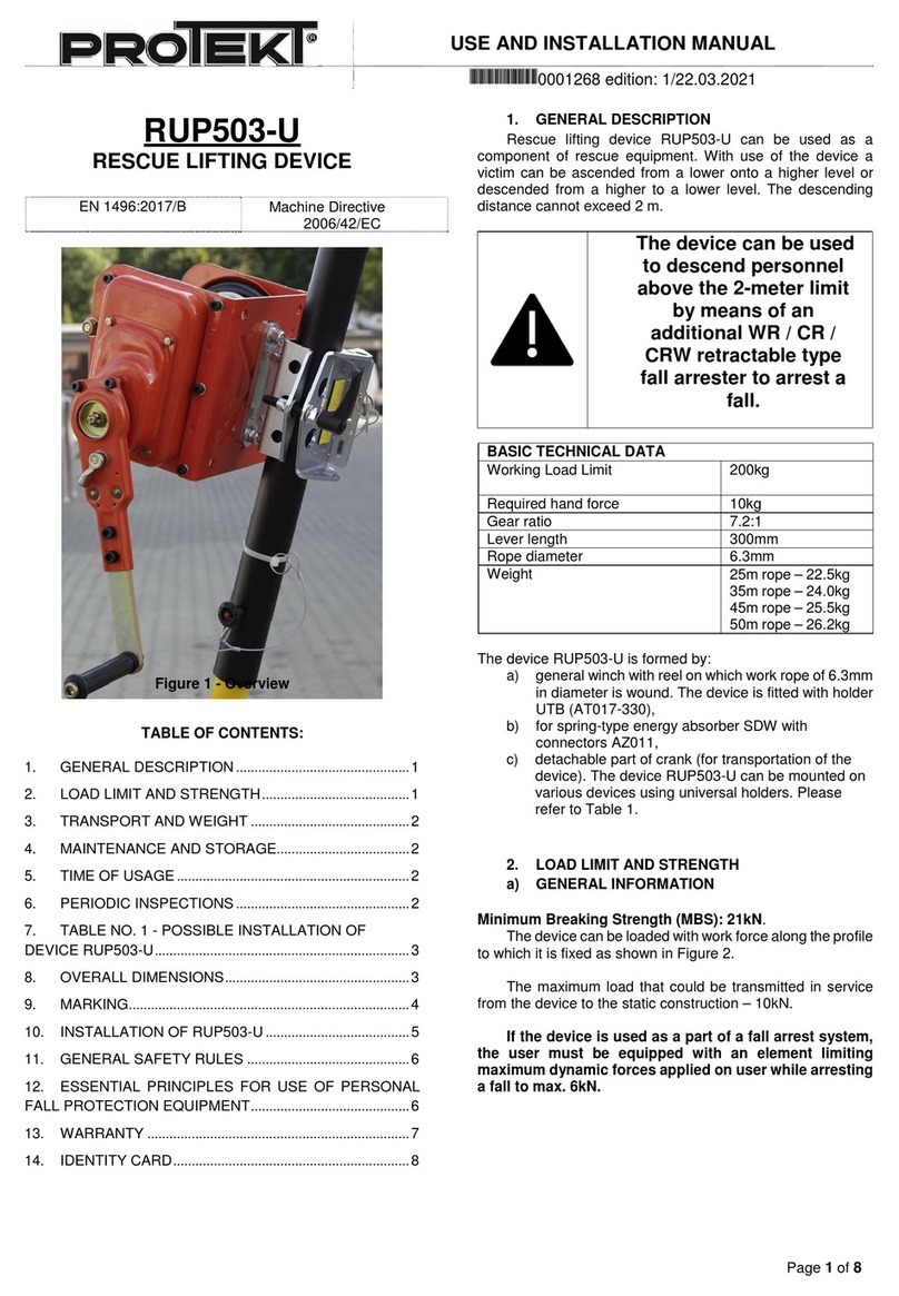
Protekt AT 050 Series User manual

grip*
locking lever
crank
reel
rope
absorber's
connector
energy
absorber
rope
connector
tripod's leg
Identity label
automatic brake inside the cover
DESIGNATED USE
The rescue lifting device RUP 502-[...] series is a component of rescue system. Using this device the rescuer can lift the other
person from a lower to higher place or lower him from a higher to lower place. Lowering distance is limited to 2 meters. The RUP
502-[...] series device complies with EN 1496:2006 / B.
Description of RUP 502-[...] series rescue lifting devices:
RUP 502 - lifting device with grip for mounting on the tripods: TM 9 / TM 9-L / TM 9-W /
•
RUP 502-A - lifting device with grip for mounting on the tripods: TM 6 / TM 12 / TM 12-2 / TM 13
•
RUP 502-B - lifting device with grip for mounting on the tripods: TM 7
•
sign "xx" - standard working rope length in meters (20, 25m)
* The grip shape may be different in particular RUP 502-[...] model variants.
TECHNICAL DATA
Working load limit:
140 kg
hand force required:
22 kg
Gear ratio:
5:1
Crank length:
300 mm
Rope diameter:
6,3 mm
Weight:
rope 20 m - 13 kg
rope 25 m - 14 kg
INSTRUCTION MANUAL
edition: 1/03.04.2014 en
EN 1496:2006 / B
READ CAREFULLY BEFORE
USE THE EQUIPMENT
RESCUE LIFTING DEVICE RUP 502-[...]
Reference
number:
AT 050-[...] xx
1/8

CORRECT !
Locking pin mounted
in the locking hole
locking pin
locking hole
WRONG !
Locking pin outside
the locking hole
locking pin
locking hole
1. Open the grip.
locking hole
grip
lockin pin
tripod's leg
2. Put the device on the tripod's leg.
Grip locking pin must be fastened
on the locking hole situated on the
outside part of the tripod's leg.
3. Close grip. Lock the grip
using the lever. Grease the
lever's thread with small amount
of constant lubricant before
installation. The winch shall not
slide on the tripod's leg.
INSTALLING ON THE TRIPOD
CAUTION!
Ensure that locking pin is properly fitted into locking hole. Locking pin prevents against device sliding on the tripod's leg.
4. Guide the rope behind two
bolts located above the reel.
2/8

2. Remove the bolts.
Remove the grip.
winch
grip
1. Unscrew four M10
nuts on the bolts
fastened the grip to the
winch in RUP 502
device.
M10 bolts
2. Remove the bolts.
Remove the grip.
winch
grip
1. Unscrew two M10
nut fastening the grip
to the winch of RUP
502-A / 502-B device.
M10 nuts
max. 60
130 2.0
max. 25mm
M10 bolts
M10 washers
(DIN 125A)
M10 self-locking nuts
(DIN 985)
10
10
45
INSTALLING DEVICE ON A STRUCTURAL ANCHOR ELEMENT
It is possible to install device directly on the structural anchor element like flat surface (e.g. wall) or steel profile. The structural
anchor element to which the device is fastened must have stable construction and have minimal static strength of 14 kN.
Construction and fastening of the structural anchor element must prevent of accidental disconnection of the device. To install
device on the structural anchor element we must remove the grip which is designed to be used only with the tripod.
REMOVING THE GRIP OF THE RUP 502 DEVICE
REMOVING THE GRIP OF THE RUP 502-A / 502-B DEVICES
INSTALLING ON THE FLAT SURFACE
Device should be installed using two holes (
10 mm and oblong
10x45) situated on the back wall of the winch.
1.
Install winch using two M10 steel mechanical or chemical anchor bolts. Anchors should be installed in accordance with the
2.
installation instructions provided by the manufacturer of the anchors.
Pu the washer M10 (DIN 125A) under each nut. Tighten two M10 self-locking nuts (DIN 985).
3.
INSTALLING ON THE FLAT SURFACE (SCREWS)
Device should be installed using four
13 mm holes situated on the back wall of the winch.
1.
Install device using four M12 steel bolts. Put the bolts through the back wall of the winch and through the holes of the
2.
structural anchor surface.
Put the washers
13 mm (DIN 125A) under the head of each bolt and under each nut. Tighten four M12 self-locking nuts
3.
(DIN 985).
3/8

M10 self-locking nuts
(DIN 985)
M10 bolts
(DIN 933)
M10 washers
(DIN 125A)
10
10
45
Device in a vertical position
energy absorber
Device in a horizontal position
energy absorber
POSITIONING OF THE DEVICE
Check the proper position of the device and correct guiding of the rope shown on the pictures below.
1.
The construction element where the winch is installed must be vertical or horizontal.
2.
Attach the energy absorber to the cable using the connector supplied with the absorber.
3.
Connect absorber's connector to the attachment element of a harness. Use "A" frontal or dorsal attachment point in full body
4.
harness (EN 361) or rescue attachment point in rescue harness (EN 1497) or rescue loops (EN 1498).
INSTALLING ON THE STEEL PROFILE
To the narrow structural elements the winch should be installed using two holes (
10 mm and oblong
10x45) situated on
1.
the back wall of the winch.
Device should be installed using two M10 steel bolts. Put the bolts through the back wall of the winch and through the
2.
structural anchor profile.
Put the washers M10 (DIN 125A) under the head of each bolt and under each nut. Tighten two M10 self-locking nuts (DIN
3.
985).
4/8

Personal protective equipment (PPE) shall only be used by a person trained and competent in its safe use.
•
PPE must not be used by a person with medical condition that could affect the safety of the equipment user in normal and
•
emergency use.
A rescue plan shall be in place to deal with any emergencies tha could arise during the work.
•
It is forbidden to make any alterations and additions to the equipment without manufacturer's prior written consent.
•
Any repairs shall only be carried out by equipment manufacturer or his certified representative.
•
PPE shall not be used outside its limitations, or of any purpose other than that for which it is intended.
•
PPE should be a personal issue item.
•
Before use ensure about the campatibility of items of equipment assembled into a fall arrest system. Periodically check
•
connecting and adjusting of the equipment components to avoid accidental loosening or disconnecting of the components.
It is forbidden to use combinations of items of equipment in which the safe function of any one item is affected by or
•
interferes with the safe function of another.
There are many hazards that may affect the performance of the equipment and corresponding safety precautions that have
•
to be observed during equipment utilization, especially: (trailing or looping of lanyards or lifelines over sharp edges; any
defects like cutting, abrasion, corrosion; climatic exposure; pendulum falls; extremes of temperature; chemical reagents;
electrical conductivity.
A full body harness conformed to EN 361 is the only acceptable body holding device that can be used in a fall arrest system.
•
The anchor device or anchor point for the fall arrest system should always be positioned, and the work carried out in such a
•
way, as to minimise both the potential for falls and potential fall distance. The anchor device/point should be placed above
the user. The shape and construction of the anchor device/point shall not allowed to self-acting disconnection of the
equipment. It is recommended to use certified and marked structural anchor point complied with EN 795.
It is obligatory to verify the free space required beneath the user at the workplace before each occassion of use the fall
•
arrest system, so that, in the case of a fall, there will be on collision with the ground or other obstacle in the fall path. The
required value of the free space should be taken from instruction manual of used equipment.
Using the energy absorber in conjuction with other elements of PPE must conform re the appropriate regulations and
•
instruction manuals and current standards: EN 361 - for harnesses; EN 353-1, EN 353-2, EN354, EN 360, EN 362 - for fall
arrest systems; EN 795 - for structural anchor points/devices.
In full body harnesses use only attaching points marked with big letter "A" to attach a fall arrest system. See the figures
•
below:
THE ESSENTIAL PRINCIPLES OF USE PERSONAL PROTECTIVE EQUIPMENT
fall arrest
system
full body
harness
attachment
point
fall arrest system
full body
harness
double-attachment
point
FORBIDDEN!
CAUTION!
It is forbidden to use the rescue lifting device as the protection against falls from height. When there is a danger of falling
•
from a height additional secondary fall arrest system conforming EN 363 must be used.
The lifting / lowering function is for rescue purposes only and not for lifting / lowering loads.
•
Always operate the device with hand power and with crank included in the equipment only.
•
Before each use of rescue device a thorough inspection must be carried out. Inspection must be carried out by a person
•
using the device. In the case of damages and malfunctions, the device should be withdrawn from use.
Never allow to full extension of the working rope from the reel. Keep at least three rope coils on the reel - it is marked by a
•
special safety sign which is situated on the rope. Stop extend the rope from the reel when the red safety sign appears!
Obligatory check a condition of the safety sign.
There should be direct or indirect visual contact or some other means of communication with the rescuer at all times
•
during the rescue process.
Using the device, in connection with fall arrest system, must be compatible with manual instructions of the fall arrest
•
systems and obligatory standards: EN 361, EN 1497, EN 1498, EN 341 - for body holding devices; EN 795 - for anchor
devices; EN 353-1, EN 353-2, EN 354, EN 355, EN 360 - for fall arrest systems, EN 362 - for the connectors.
STOP EXTEND
THE ROPE FROM
REEL WHEN THE
RED SAFETY
SIGN APPEARS
5/8

INSPECTION
Before each use of Personal Protective Equipment (PPE) it is obligatory to carry out a pre-use check of the equipment, to ensure
that it is in a serviceable condition and operates correctly before it is used.
During pre-use check it is necessary to inspect all elements of the equipment in respect of any damages, excessive wear,
corrosion, abrasion, cutting or incorrect acting, especially in rescue lifting devices - cable (wires, clips, ferrules, loops, thimbles,
connectors, adjusting elements) and automatic brake proper acting, casing, energy absorber (attaching loops, connectors),
connectors (main body, rivets, gate, locking gear acting).
PERIODIC INSPECTION
After each 12 months of utilization the rescue lifting device must be withdrawn from use to carry out manufacturer's detailed
inspection. The inspection must be carried out by the rescue lifting device manufacturer or his certified representative only.
During this inspection will be established admissible time of the device use till next manufacturer's inspection.
The result of inspection must be recorded in Identity Card.
Regular periodic inspections are the essential for equipment maintenance and the safety of the users which depends upon the
continued efficiency and durability of the equipment.
During periodic inspections it is necessary to check the legibility of the equipment marking.
It is essential for the safety of the user that if the product is re-sold outside the original country of destination the reseller shall
provide instruction for use, for maintenance, for periodic examination and for repair in language of the country in which the
product is to be used.
WITHDRAWAL FROM USE
Personal protective equipment must be withdrawn from use immediately when any doubt arise about its condition for safe use
and not used again until confirmed in writing by equipment manufacturer or his certified representative after carried out the
detailed inspection.
WITHDRAWAL FROM USE AFTER ARREST A FALL
Personal protective equipment must be immediately withdrawn from use when it has been component of equipment used to
arrest a fall. After that the detailed manufacturer's inspection must be carried out.
Detailed manufacturer's inspection can be carried out by:
- equipment manufacturer;
- or person recommended by manufacturer
- a company recommended by manufacturer.
During this inspection will be established if the device can be longer used and will be define the admissible time of device use till
next manufacturer's inspection. If the device can not be longer used it will be subjected to destroyed.
TRANSPORTATION
PPE must be transported in the package (e.g. bag made of moisture-proof textile or foil bag or cases made of steel or plastic) to
protect it against damage or moisture.
MAINTENANCE AND STORAGE
PPE can be cleaned and desinfected without causing adverse effect on the materials in the manufacture the equipment. For
textile products use mild detergents for delicate fabrics, wash by hand or in a machine and rinse in water. Plastic parts can be
cleaned only with water. When the equipment becomes wet, either from being in use or when due cleaning, it shall be allowed to
dry naturally, and shall be kept away from direct heat. In metallic products some mechanic parts (spring, pin, hinge, etc.) can be
regularly slightly lubricated to ensure better operation.
PPE should be stored loosely packed, in a well-ventilated place, protected from direct light, ultraviolet degradation, damp
environment, sharp edges, extreme temperatures and corrosive or aggressive substances.
6/8

a
b
c
d
f
g
h
i
j
e
CONTENT OF THE IDENTITY LABEL
a) Device type.
b) Model symbol.
c) Reference number.
d) Number/year/class of the European standard.
e) Rescue equipment - information.
f) Month and year of manufacture.
g) Serial number of the tripod.
h) Caution: read the manual.
i) Marking of the manufacturer or distributor of the tripod.
j) Maximum load limit
.
The Notified Body involved with EC type examination and in the production control
phase: APAVE SUDEUROPE SAS, CS 60193, 13322 Marseille, France.
7/8

IDENTITY CARD
IT IS RESPONSIBILITY OF THE USER ORGANISATION TO PROVIDE THE IDENTITY CARD AND TO FILL IN THE DETAILS REQUIRED. THE IDENTITY
CARD SHOULD BE FILLED IN ONLY BY COMPETENT PERSON RESPONSIBLE FOR PROTECTIVE EQUIPMENT. THE IDENTITY CARD SHOULD BE FILLED
IN BEFORE THE FIRST USE OF THE EQUIPMENT. ANY INFORMATION ABOUT THE EQUIPMENT LIKE: PERIODIC INSPECTIONS, REPAIRS, REASONS OF
EQUIPMENT’S WITHDRAWN FROM USE SHALL BE NOTED. THE IDENTITY CARD SHOULD BE STORAGED DURING A WHOLE PERIOD OF EQUIPMENT
UTILIZATION. DO NOT USE THE EQUIPMENT WITHOUT THE IDENTITY CARD.
PRODUCER:
PROTEKT, 93-403 LODZ, ul. Starorudzka 9, POLAND, tel: +48 (42) 680 20 83, fax: +48 (42) 680 20 93, www.protekt.com.pl
NOTES
.............................................................................................................................................................................................................
.............................................................................................................................................................................................................
.............................................................................................................................................................................................................
.............................................................................................................................................................................................................
MODEL AND TYPE OF EQUIPMENT
REF. NUMBER
SERIAL NUMBER
DATE OF MANUFACTURE
DATE OF PURCHASE
DATE OF FIRST USE
USER NAME
PERIODIC EXAMINATION AND REPAIR HISTORY
DATE
REASON FOR SERVICING /
REPAIR
REPAIRS CARRIED OUT
NAME AND
SIGNATURE OF
COMPETENT PERSON
DATE OF
NEXT
EXAMINATION
1
2
3
4
5
6
7
8
9
8/8
This manual suits for next models
4
Other Protekt Lifting System manuals