PROTRONIX NLII-CO2-R-5-A User manual

NLII-CO2-R-5-A |
Room sensor CO2with sound alarm
1/6
Protronix s.r.o., Pardubická 177, Chrudim 537 01, Czech Republic www.protronix.cz/en/ www.careforair.eu/en/
User manual
um-nlii-co2-r-5-a-en-v4-211115
.docx
Room sensor NLII-CO2 is used to continuously
monitor air quality inside buildings and then
control ventilation (HVAC) systems according to
current levels of internal air quality. The sensor
measures concentration of carbon dioxide (CO2) in
air. It is suitable for schools, offices, classrooms,
shopping centers, homes, restaurants, fitness
centers, commercial buildings, etc.
measures CO2
analog voltage/current output
2x output relay –2x NO/C
sound signalization –alarm
two modes of relay switching
maintenance during operation not required
long life and stability
Description
The measuring of CO2is based on the principle of infrared
radiation attenuation dependence on the CO2concentration
in the air (NDIR). Built-in auto-calibration function ensures
very good long term stability.
The sensor has built-in one analog output for the actual
concentration of CO2. Relay trigger level can be set by SET
POINT rotary switch.
Relay switching is indicated simultaneously with a short (1,5s)
audible signal and yellow LED light.
The way of relay switching can be set by a jumper –5s pulses
when the CO2concentration exceeds and falls below the set
CO2level for e.g. opening and closing a skylight, or standard
switching, where relays are closed until the measured CO2
concentration drops under the set CO2level.
So the sensor efficiently manages ventilation and heat
recovery units, based on current room air quality.
The current air quality can easily be determined by looking at
the three LED indicators. The eco level means good indoor air
quality necessary to achieve a sense of well-being and at the
same time optimal energy costs for heating, ventilation or air
conditioning.
Explanation of abbreviations and technical terms can be
found on our website in the Glossary section.
Technical data
Type of sensor / Order code
CO2output
Relay
NLII-CO2-R-5-A
0-10 V/0-20 mA/4-20 mA1)
1x NO/C
NLII-CO2-2R-5-A
0-10 V/0-20 mA/4-20 mA1)
2x NO/C
1) It is possible to select the desired type of analog output by a jumper on the electronics board. Minimum achievable output value
corresponds to minimum value of the measuring range.
Parameter
Value
Unit
Supply voltage range
12 –35
12 –24
V DC
V AC
Average consumption
0,5
W
CO2 measuring range
400 –5000
ppm
CO2accuracy
± 35 ppm ±5 % of reading
CO2 relay - hysteresis
100
ppm
CO2rate rise
max 1
min
CO2step response
(90 %) 80
s
Max. switching voltage
250/30
V AC / V DC
Max. switching current
5/5
A AC / A DC
Working humidity
no condensing
5 –95 %
RH
Working temperature
0 to +50
°C
Storage temperature
-20 to +60
°C
Expected lifetime
min. 10
years
Ingress protection
IP20
Dimensions
90x80x31
mm

NLII-CO2-R-5-A |
Room sensor CO2with sound alarm
2/6
Protronix s.r.o., Pardubická 177, Chrudim 537 01, Czech Republic www.protronix.cz/en/ www.careforair.eu/en/
User manual
um-nlii-co2-r-5-a-en-v4-211115
.docx
CO2sensor autocalibration function
Autocalibration compensates for long-term aging of the
key components of the sensor. This function is available
only when sensor power supply is continuous and
uninterrupted. Calibration during operation is not
necessary.
Selected analog output values versus CO2
concentration
LED indication description
White LED lights:
Less than 600 ppm CO2.
maintaining low concentrations of CO2is not
cost-effective - slightly increased
concentration does not cause any health
complications
Green LED lights:
More than or equal to 600 ppm CO2, less than or
equal to 1200 ppm CO2.
optimal balance of air quality and energy
efficiency of ventilation and air conditioning
Yellow LED lights + sound alarm:
When the measured CO2concentration exceeds
the level set by SET POINT rotary switch.
yellow LED lights always when the measured
CO2concentration exceeds the level set by
SET POINT rotary switch (min 1000ppm),
simultaneously the sound alarm is triggered
and the relay contacts close. Sensor remains
in this state for 2 minutes –see relay
switching graph below.
CO2concentration higher than 1200 ppm can
cause fatigue, restlessness, headache and
feeling uncomfortable, hot etc.
Sensor start after power on
All three LEDs flash simultaneously until the first
readings are available, but no longer than 10 seconds.
Sensor failure indication
All three LEDs are shining permanently.
CAUTION:
Warm-up: operational after 1 minute since power on.
The declared accuracy is reached after 4 days of
continuous power supply.
It is necessary to avoid severe mechanical shock of the
sensor.

NLII-CO2-R-5-A |
Room sensor CO2with sound alarm
3/6
Protronix s.r.o., Pardubická 177, Chrudim 537 01, Czech Republic www.protronix.cz/en/ www.careforair.eu/en/
User manual
um-nlii-co2-r-5-a-en-v4-211115
.docx
Electronic board controls and terminals
Terminals
1. ~ + power AC or DC (+) plus pole
2. ~ GND power AC or DC (-) minus pole, GND
3. OUT1 CO2sensor analog output, 0-10 V or 0-20
mA or 4-20 mA
4. GND CO2sensor output GND
5. OUT2 unused
6. GND unused
7. OUT3 NO relay 2 output, normally open (RH)
8. OUT4 C output relay, common contact
9. OUT5 NO relay 1 output, normally open (CO2)
SET POINT rotary switch for setting the relays
switching level
RELAY 1 –switching level for CO2setting
Jumpers
JP1 –unused
JP2 –Current output offset CO2
JP3 –Voltage/current output CO2
JP4 –unused
JP6 –LED indication and switching mode settings
9
8
7
6
5
4
3
2
1
NLII-CO2-R-5-A |
Room sensor CO2with sound alarm
4/6
Protronix s.r.o., Pardubická 177, Chrudim 537 01, Czech Republic www.protronix.cz/en/ www.careforair.eu/en/
User manual
um-nlii-co2-r-5-a-en-v4-211115
.docx
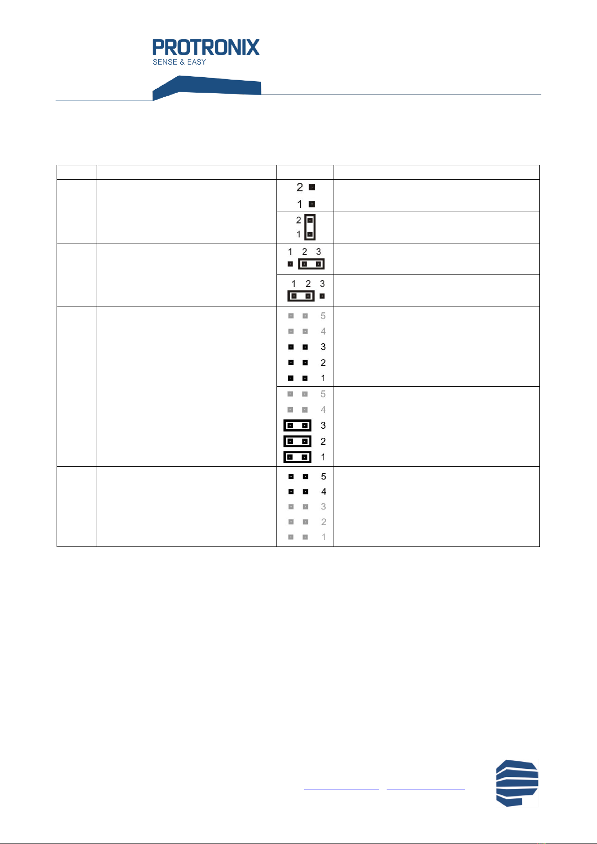
Jumpers on the electronics board
Mark
Description
Settings
Meaning
JP2
Current output offset CO2
- shift quiescent current from 0 mA to
4 mA
current output CO20-20 mA
current output CO24-20 mA
JP3
Voltage/current output CO2
- select the type of analog output
- if the selected voltage output is CO2,
JP2 must not be shorted
voltage output CO2
current output CO2
JP6 - 1
JP6 - 2
JP6 - 3
Switching mode, signalization and alarm
-LED indication according to ambient
light - when ambient light is dimmed (at
night), LED indicators turn off
automatically.
relays contacts closed until concentration drops
sound alarm disabled
LED indication according to ambient light
relays switching in 5s pulses
sound alarm enabled
permanent LED indication enabled
JP6 - 4
JP6 - 5
These positions are not intended for
user setting.
Setting the relay switching mode using jumper JP6-3 and SET POINT rotary switch
If the jumper JP6-3 is closed, relay 1 contacts close for 5s always, when the measured concentration of CO2rises above
the level set by the SET POINT rotary switch.
When the measured concentration of CO2drops below the level set by SET POINT switch minus the hysteresis value of
100 ppm, relay 2 contacts close for 5s.
If the jumper JP6-3 is open, both relays contacts close, when the measured concentration of CO2rises above the level
set by the SET POINT rotary switch and stay close until the measured concentration drops below the level set by SET
POINT switch minus the hysteresis value of 100 ppm.
Minimum delay between changes of relays state is 2 minutes.

NLII-CO2-R-5-A |
Room sensor CO2with sound alarm
5/6
Protronix s.r.o., Pardubická 177, Chrudim 537 01, Czech Republic www.protronix.cz/en/ www.careforair.eu/en/
User manual
um-nlii-co2-r-5-a-en-v4-211115
.docx
Relay switching graph with 1 relay (NLII-CO2-R-5-A)
Setting the switching levels
Required concentration of CO2
SET POINT
CO2[ppm]
0
1000
1
1100
2
1200
3
1300
4
1400
5
1500
6
1600
7
1700
8
1800
9
1900
A
2000
B
2100
C
2200
D
2300
E
2400
F
2500
Relay switching graph with 2 relays (NLII-CO2-2R-5-A)
Example for setting the concentration of 1500 ppm
Factory settings
LED indication: indication turns off when
ambient light dims
CO2analog output: voltage output
Relay switching mode: relays switching in 5s pulses
Switching level CO2: 1500 ppm
Sound alarm: enabled

NLII-CO2-R-5-A |
Room sensor CO2with sound alarm
6/6
Protronix s.r.o., Pardubická 177, Chrudim 537 01, Czech Republic www.protronix.cz/en/ www.careforair.eu/en/
User manual
um-nlii-co2-r-5-a-en-v4-211115
.docx
The producer reserves the right of technical changes in order to product improvements its properties and functions
without previous notice.
If you connect other devices to the same AC power source as the NL sensor, it is necessary to meet GND wiring of
all analog inputs and outputs, as well as power wires.
Dimensions
Sensor assembly
Box color
Front: white - RAL9016
Base: gray - RAL7035
Way to use
The product is intended for indoor use only. You can
read the recommendations for sensor placement on
our web pages.
End of product life
Discard the product in according to the electronic
waste law and the EU directives.


