manuals.online logo
Brands
  1. Home
  2. •
  3. Brands
  4. •
  5. Sauder
  6. •
  7. Storage
  8. •
  9. Sauder Soft Modern 415143 User manual

Sauder Soft Modern 415143 User manual

sauder.com
Your holder for all
things awesome.
sauder.com
NOTE: THIS INSTRUCTION
BOOKLET CONTAINS IMPORTANT
SAFETY INFORMATION.
PLEASE READ AND KEEP FOR
FUTURE REFERENCE.
English pg 1-22
Français pg 23-25
Español pg 26-28
Lot # 355339 09/24/13
Purchased: __________________________
Be sure to give us a ring before
making any returns. 1-800-523-3987
Need help? Visit Sauder.com to view video assembly tips or chat with a live rep.
Prefer the phone? Call 1-800-523-3987.
Share your journey!
Cubby Storage Cabinet
Soft Modern Collection | 415143
Table of Contents Assembly Tools Required
2-3
4
5-22
23-25
26-28
29-30
31
Part Identification
Hardware Identification
Assembly Steps
Français
Español
Safety
Warranty
Hammer
Not actual size
No. 2 Phillips Screwdriver
Tip Shown Actual Size
Part Identification
A RIGHT END (1)
B LEFT END (1)
C UPRIGHT (3)
D SHORT UPRIGHT (2)
E RIGHT DOOR UPRIGHT (1)
F LEFT DOOR UPRIGHT (1)
G TOP (1)
H BOTTOM (1)
I SHELF (1)
J DOOR SHELF (4)
K BACK (1)
L DOOR (2)
M LEFT DOOR END (1)
N ADJUSTABLE SHELF (2)
O SMALL ADJUSTABLE SHELF (6)
P RIGHT DOOR END (1)
Q WIDE LONG SIDE MOLDING (4)
R DOOR SHELF STOP (4)
SNARROW SHORT CORNER
DOOR MOLDING (4)
TNARROW LONG
BACK MOLDING (2)
U WINEGLASS MOLDING (2)
V WIDE WINEGLASS MOLDING (1)
W WIDE SHORT DOOR MOLDING (8)
Short Screwdriver
å While not all parts are labeled, some of the parts will have a label or an inked letter on the edge
to help distinguish similar parts from each other. Use this part identification to help identify similar parts.
Tape Measure
415143 www.sauder.com/servicesPage 2
Part Identification
A
B
C
D
E
F
G
H
I
J
K
L
M
N
O
P
Q
R
S
T
U
V
W
D
U
T
C
C
O
O
O
O
O
N
J
R
J
R
J
R
L
W
WW
WWW
W
S
S
S
Q
Q
Q
415143www.sauder.com/services Page 3
Hardware Identification
åScrews are shown actual size. You may receive extra hardware with your unit.
BLACK 9/16" LARGE HEAD SCREW - 28
1S
SILVER 1-1/8" FLAT HEAD SCREW - 54
10S
BLACK 1-1/4" FLAT HEAD SCREW - 6
7S
BLACK 1-7/8" FLAT HEAD SCREW - 16
2S
RUBBER SLEEVE - 32
2R
METAL PIN - 48
1R
MAGNETIC CATCH - 2
2I
BLACK 1/2" FLAT HEAD SCREW - 2
11S
STRIKE PLATE - 2
6I
NAIL - 46
1N
HIDDEN CAM - 40
1F CAM DOWEL - 40
2F
FOOT - 4
29E
HINGE SET - 2
32H
415143 www.sauder.com/servicesPage 4
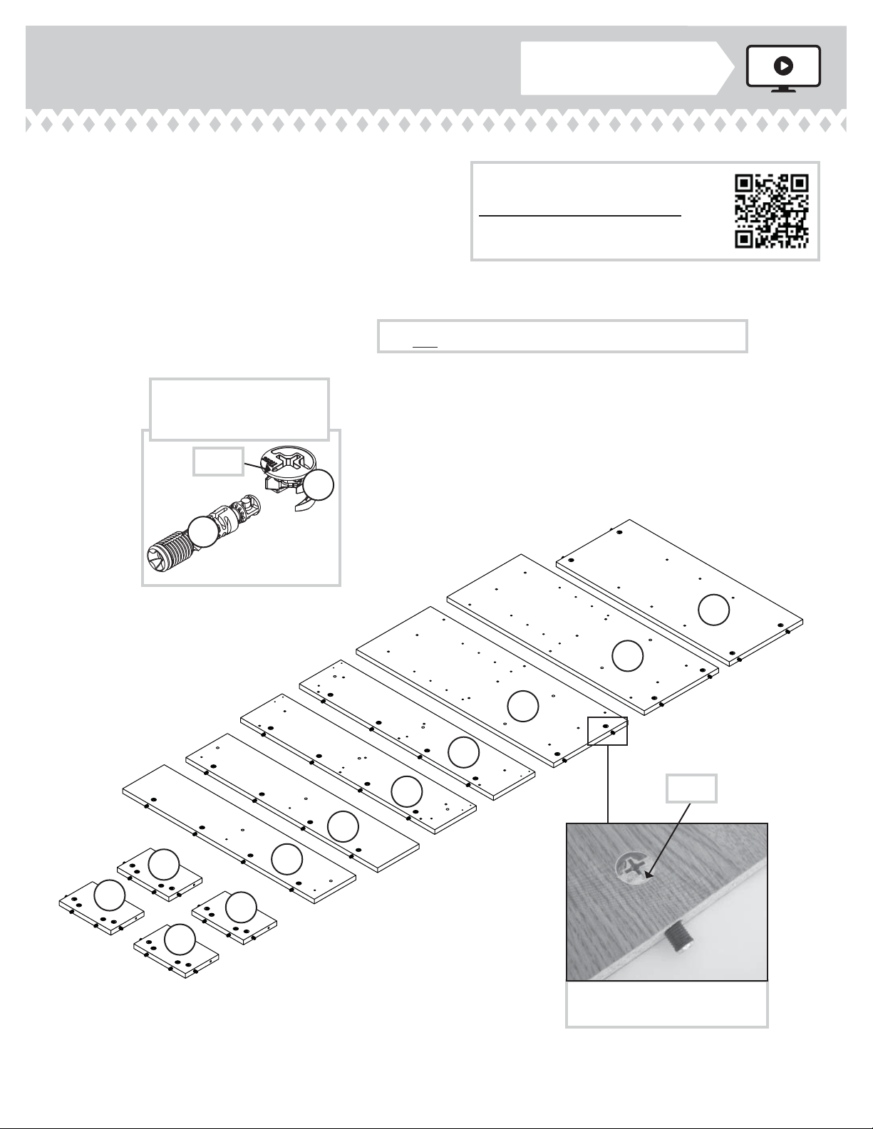
Step 1 Look for this icon. It means a
video assembly tip is available at
www.sauder.com/services/tips
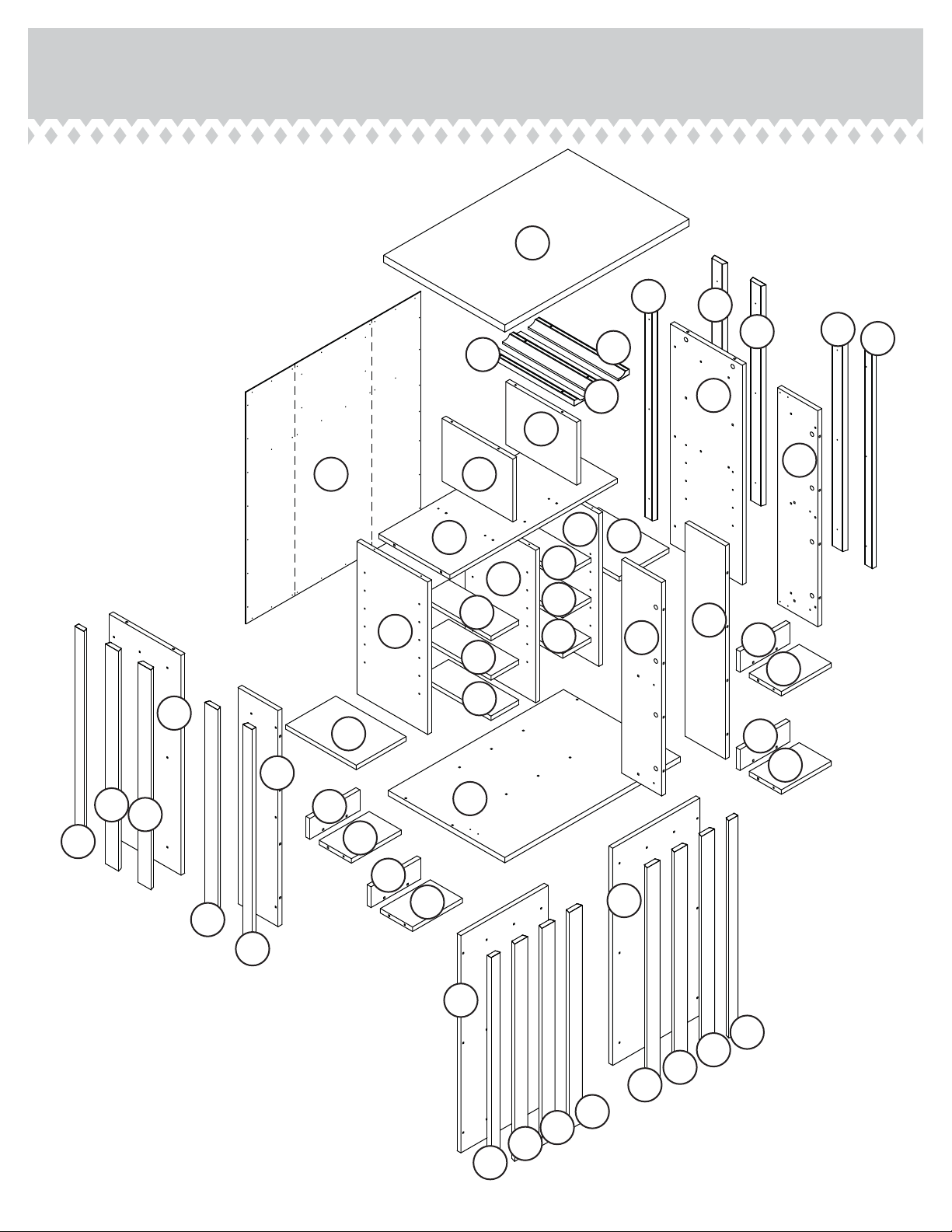
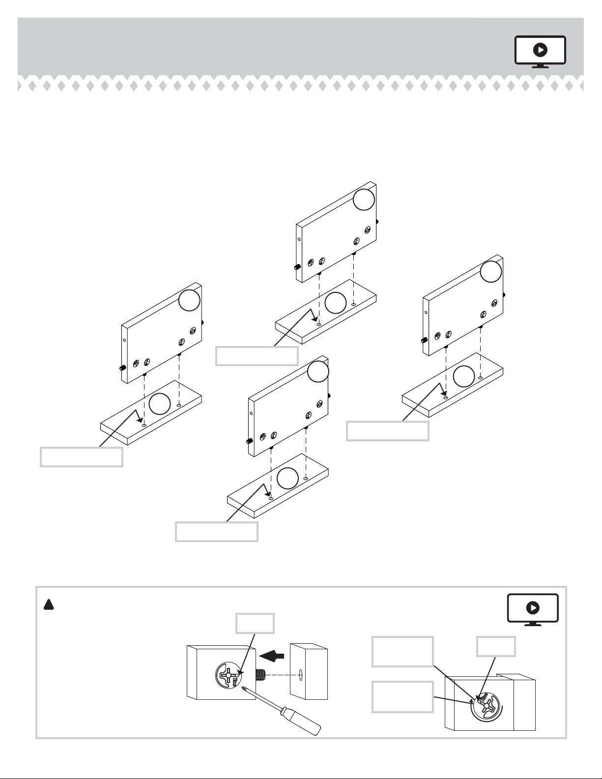
å Assemble your unit on a carpeted floor or on the empty
carton to avoid scratching your unit or the floor.
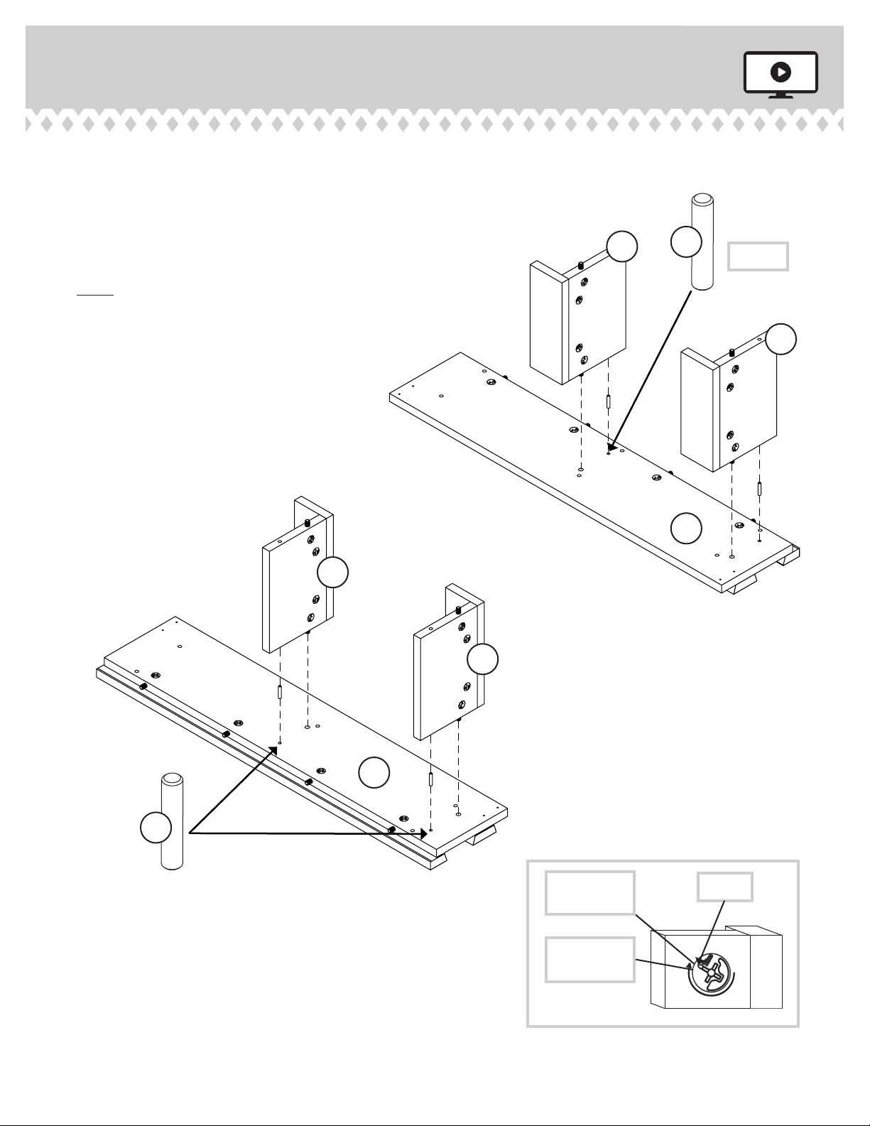
å Push forty HIDDEN CAMS (1F) into the
ENDS (A and B), DOOR UPRIGHTS (E and F), SHELF (I),
DOOR SHELVES (J), and DOOR ENDS (M and P). Then,
insert the metal end of a CAM DOWEL (2F) into each
HIDDEN CAM.
Do not tighten the HIDDEN CAMS in this step.
(40 used)
Arrow
1F
2F
Insert the metal end of the CAM
DOWEL into the HIDDEN CAM.
Arrow
The arrow in the HIDDEN
CAM must point toward the
hole in the edge of the board.
A
B
E
F
I
J
M
P
J
J
J
415143www.sauder.com/services Page 5
Scan this QR code or go to this address:
http://qr.sauder.com/?ID=1211
to watch a video on how to assemble your unit.
å Fasten the WIDE LONG SIDE MOLDINGS (Q) and
NARROW LONG BACK MOLDINGS (T) to the
ENDS (A and B). Use eighteen SILVER 1-1/8" FLAT
HEAD SCREWS (10S).
å NOTE: These MOLDINGS have unfinished ends.
Step 2
A
B
Q
T
T
Q
Q
Q
SILVER 1-1/8" FLAT HEAD SCREW
(18 used in this step)
10S
Surface with
HIDDEN CAMS
Surface with
HIDDEN CAMS
Unfinished ends
Unfinished ends
Angled edge
Angled edge
415143 www.sauder.com/servicesPage 6
å Fasten two NARROW SHORT CORNER DOOR
MOLDINGS (S) and six WIDE SHORT DOOR
MOLDINGS (W) to the DOORS (L). Use twenty-four
SILVER 1-1/8" FLAT HEAD SCREWS (10S).
å NOTE: The MOLDINGS (S) will hang over the edges of
the DOORS (L).
Step 3
L
L
SILVER 1-1/8" FLAT HEAD SCREW
(24 used in this step)
10S
These holes must be here.
Surface with
more holes Surface with
more holes
S
W
S
W
W
W
W
W
Angled edge
Angled edge
415143www.sauder.com/services Page 7
å Fasten two NARROW SHORT CORNER DOOR MOLDINGS (S) and two
WIDE SHORT DOOR MOLDINGS (W) to the DOOR ENDS (M and P).
Use twelve SILVER 1-1/8" FLAT HEAD SCREWS (10S).
å NOTE: The MOLDINGS (S) will hang over the edges of the
DOOR ENDS (M and P).
Step 4
M
P
S
W
W
S
Surface with
HIDDEN
CAMS
Surface with
HIDDEN
CAMS
Edge with HIDDEN CAMS
and CAM DOWELS
Edge with HIDDEN CAMS
and CAM DOWELS
SILVER 1-1/8" FLAT HEAD SCREW
(12 used in this step)
10S
Angled edge
Angled edge
415143 www.sauder.com/servicesPage 8
å Fasten the DOOR SHELF STOPS (R) to the DOOR
SHELVES (J). Tighten eight HIDDEN CAMS.
Step 5
Start Tighten
Arrow
Minimum
190 degrees
Caution
Risk of damage or
injury. HIDDEN CAMS
must be completely
tightened. HIDDEN
CAMS that are not
completely tightened
may loosen, and parts
may separate. To
completely tighten:
!
Arrow
Maximum
210 degrees
R
R
R
J
R
Surface with
HIDDEN CAMS
J
Surface with
HIDDEN CAMS
J
Surface with
HIDDEN CAMS
J
Surface with
HIDDEN CAMS
Surface with holes
415143www.sauder.com/services Page 9
Surface with holes
Surface with holes
Surface with holes
å Insert four METAL PINS (1R) into the holes indicated in the
DOOR ENDS (M and P).
å Fasten the DOOR SHELVES (J) to the DOOR
ENDS (M and P). Tighten four HIDDEN CAMS.
å NOTE: Be sure the METAL PINS in the DOOR ENDS insert
into the DOOR SHELVES.
Step 6
Arrow
Minimum
190 degrees
Maximum
210 degrees
(4 used)
1R
1R
Surface
with
HIDDEN
CAMS
Surface
with
HIDDEN
CAMS
Surface
with
HIDDEN
CAMS
Surface
with
HIDDEN
CAMS
J
J
J
J
M
P
Surface
with
HIDDEN
CAMS
Surface
with
HIDDEN
CAMS
415143 www.sauder.com/servicesPage 10
å Insert four METAL PINS (1R) into the holes in the edges of
the DOOR SHELVES (J).
å Fasten the DOOR UPRIGHTS (E and F) to the DOOR
SHELVES (J). Tighten four HIDDEN CAMS.
å NOTE: Be sure the METAL PINS in the DOOR SHELVES
insert into the DOOR UPRIGHTS.
å NOTE: This step will be easier with a short screwdriver.
Step 7
Arrow
Minimum
190 degrees
Maximum
210 degrees
J
J
J
J
Surface
without
HIDDEN
CAMS
Surface
without
HIDDEN
CAMS
F
E
Edge with CAM DOWELS
(4 used)
1R
1R
415143www.sauder.com/services Page 11
å Fasten the DOOR UPRIGHTS (E and F) and DOOR
ENDS (M and P) to the DOORS (L). Tighten sixteen
HIDDEN CAMS
å NOTE: This step will be easier with a short screwdriver.
Step 8
Arrow
Minimum
190 degrees
Maximum
210 degrees
Surface with
HIDDEN CAMS
Surface with
HIDDEN CAMS
Surface without
HIDDEN CAMS
Surface with MOLDINGS
Edge with MOLDING past
the edge of the DOOR.
L
L
P
E
F
M
No SHELF on this end.
Edge with MOLDING past
the edge of the DOOR.
415143 www.sauder.com/servicesPage 12
å Fasten four HINGES (32H) to the DOOR ENDS (M and P).
Use eight BLACK 9/16" LARGE HEAD SCREWS (1S).
å Fasten two STRIKE PLATES (6I) to the DOORS (L). Use
two BLACK 1/2" FLAT HEAD SCREWS (11S).
Step 9
P
E
F
M
L
L
32H
32H
32H
32H
6I
BLACK 9/16" LARGE HEAD SCREW
(8 used for the HINGES)
1S
BLACK 1/2" FLAT HEAD SCREW
(2 used for the STRIKE PLATES)
11S
415143www.sauder.com/services Page 13
å Fasten the WINEGLASS MOLDINGS (U and V) to the
TOP (G). Use six BLACK 1-1/4" FLAT HEAD SCREWS (7S).
å Push two MAGNETIC CATCHES (2I) into the TOP (G).
Step 10
G
U
V
U
Surface
with holes
2I
BLACK 1-1/4" FLAT HEAD SCREW
(6 used in this step)
7S
Flat surface
Flat edge
Flat edge
415143 www.sauder.com/servicesPage 14
Finished edge
å Fasten the SHELF (I) to the LEFT END (B). Tighten two
HIDDEN CAMS.
Step 11
I
B
Surface with HIDDEN CAMS
Surface with
HIDDEN CAMS
Minimum
190 degrees
Maximum
210 degrees Arrow
Finished edge
Finished edge
Do not stand the unit upright without the
BACK fastened. The unit may collapse.
Caution
415143www.sauder.com/services Page 15
å Fasten the UPRIGHTS (C) to the SHELF (I) as shown in the
upper diagram. Use six BLACK 1-7/8" FLAT
HEAD SCREWS (2S).
å NOTE: The distance of the holes from the top and bottom
edges on the UPRIGHTS (C) need to be measured for the
correct attachment of the UPRIGHTS.
å Fasten the BOTTOM (H) to the LEFT END (B) and
UPRIGHTS (C) as shown in the lower diagram. Use eight
BLACK 1-7/8"FLAT HEAD SCREWS (2S).
Step 12
C
C
C
I
Finished edge
Unfinished surface
Finished edge
C
C
C
B
BLACK 1-7/8" FLAT HEAD SCREW
(8 used for the BOTTOM)
2S
H
5"
3 1/2"
BLACK 1-7/8" FLAT HEAD SCREW
(6 used for the TOP)
2S
2S
415143 www.sauder.com/servicesPage 16
Step
å Fasten the RIGHT END (A) to the SHELF (I). Tighten two
HIDDEN CAMS
å Fasten the RIGHT END (A) to the BOTTOM (H). Use two
BLACK 1-7/8" FLAT HEAD SCREWS (2S).
å Insert four METAL PINS (1R) into the holes in the SHELF (I).
å Push the SHORT UPRIGHTS (D) onto the METAL PINS in
the SHELF.
Step 13
D
D
I
Finished edge
1R
Finished edge
(4 used)
A
H
BLACK 1-7/8" FLAT HEAD SCREW
(2 used in this step)
2S Minimum
190 degrees
Maximum
210 degrees Arrow
415143www.sauder.com/services Page 17
Step
å Insert four METAL PINS (1R) into the holes near the
WINEGLASS MOLDINGS (U) in the TOP (G).
å Fasten the TOP (G) to the ENDS (A and B). Tighten four
HIDDEN CAMS.
Step 14
Minimum
190 degrees
Maximum
210 degrees Arrow
1R
(4 used)
G
V
U
U
Surface with holes
MAGNETIC CATCHES
must be here.
415143 www.sauder.com/servicesPage 18
Step
å Fasten the FEET (29E) to the BOTTOM (H). Use twelve
BLACK 9/16" LARGE HEAD SCREWS (1S).
Step 15
29E
29E 29E
29E
BLACK 9/16" LARGE HEAD SCREW
(12 used in this step)
1S
H
415143www.sauder.com/services Page 19
StepStep 16
å Carefully turn your unit over onto its front edges. Unfold
the BACK (K) and lay it over your unit.
å Make equal margins along all four edges of the
BACK (K). Push on opposite corners of your unit if
needed to make it “square”.
å Fasten the BACK (K) to your unit using the NAILS (1N).
å NOTE: Be sure to tap NAILS into the holes that line up
over the SHELF (I) and SHORT UPRIGHTS (D).
Unfinished
surface
NAIL
(46 used in this step)
1N
These holes must line up
over the SHELF (I) and
SHORT UPRIGHTS (D).
K
Do not stand the unit upright without the
BACK fastened. The unit may collapse.
Caution
415143 www.sauder.com/servicesPage 20

Other Sauder Storage manuals

Sauder OFFICE WORKS AFFIRM 427869 User manual

Sauder

Sauder OFFICE WORKS AFFIRM 427869 User manual

Sauder HomePlus 411572 User manual

Sauder

Sauder HomePlus 411572 User manual

Sauder Tuff Duty 409263 User manual

Sauder

Sauder Tuff Duty 409263 User manual

Sauder 421191 User manual

Sauder

Sauder 421191 User manual

Popular Storage manuals by other brands

Toshiba MK6025GAS user manual

Toshiba

Toshiba MK6025GAS user manual

HP StorageWorks 2000fc Replacement instructions

HP

HP StorageWorks 2000fc Replacement instructions

Fujitsu ETERNUS DX100 S3 Setup guide

Fujitsu

Fujitsu ETERNUS DX100 S3 Setup guide

Spectra Logic Spectra 12K user guide

Spectra Logic

Spectra Logic Spectra 12K user guide

IBM Ultrastar 36LP Quick installation guide

IBM

IBM Ultrastar 36LP Quick installation guide

Keter Samoa Assembly instructions

Keter

Keter Samoa Assembly instructions

Rasilient PixelStor 5000 user manual

Rasilient

Rasilient PixelStor 5000 user manual

HP 12Gb SAS SSDs Quickspecs

HP

HP 12Gb SAS SSDs Quickspecs

VERITAS 5350 quick start guide

VERITAS

VERITAS 5350 quick start guide

Adaptec 1821900 Reference

Adaptec

Adaptec 1821900 Reference

Robinson Regatta Assembly instructions

Robinson

Robinson Regatta Assembly instructions

I-O DATA HDC-UXW Series Setup guide

I-O DATA

I-O DATA HDC-UXW Series Setup guide

SmartDisk FireLite Specifications

SmartDisk

SmartDisk FireLite Specifications

Western Digital Computer Hard Drive installation guide

Western Digital

Western Digital Computer Hard Drive installation guide

Seagate ST9100822A installation guide

Seagate

Seagate ST9100822A installation guide

OWC Mercury Elite Pro Dual Assembly manual & user guide

OWC

OWC Mercury Elite Pro Dual Assembly manual & user guide

Copernicus Tech Tub2 Assembly guide

Copernicus

Copernicus Tech Tub2 Assembly guide

HP P9000 user guide

HP

HP P9000 user guide

manuals.online logo
manuals.online logoBrands
  • About & Mission
  • Contact us
  • Privacy Policy
  • Terms and Conditions

Copyright 2025 Manuals.Online. All Rights Reserved.