METER ATMOS 41 User manual

ATMOS 41

i
TABLE OF CONTENTS
1. Introduction..............................................................................................1
2. Operation ...................................................................................................2
2.1 Installation ................................................................................................2
2.2 Connecting................................................................................................. 4
2.2.1 Connect to METER Data Logger........................................................ 4
2.2.2 Connect to a Non-METER Logger .....................................................5
3. System.........................................................................................................7
3.1 Specifications............................................................................................7
3.2 Pyranometer ............................................................................................ 11
3.3 Anemometer ............................................................................................ 12
3.4 Vapor Pressure/Relative Humidity Sensor ............................................... 13
3.5 Rain Gauge............................................................................................... 14
3.6 Temperature Sensor................................................................................. 16
3.7 Lightning Sensor...................................................................................... 16
3.8 Configure the Lightning Sensor Using ProCheck ...................................... 17
3.9 Barometric Pressure Sensor .................................................................... 17
3.10 Tilt Sensor.............................................................................................. 18
3.11 Theory.................................................................................................... 18
3.11.1 Wind Speed and Direction............................................................ 18
3.11.2 Temperature Sensor..................................................................... 20
3.12 Limitations............................................................................................. 21
3.12.1 Snow and Ice Accumulation ......................................................... 21
3.12.2 Heavy Rain and Strong Wind ........................................................ 21
..................................... 22
18169-02
6.8.2018

ii
4. Service....................................................................................................... 24
4.1 Calibration ............................................................................................... 24
4.2 Recalibration Recommendations............................................................. 25
4.3 Cleaning and Maintenance....................................................................... 25
4.4 Troubleshooting....................................................................................... 27
4.5 Customer Support.................................................................................... 29
4.6 Terms and Conditions .............................................................................. 29
References .................................................................................................... 30
Index ................................................................................................................. 31


1
1. INTRODUCTION
Thank you for choosing the ATMOS41 All-in-One Weather Station from METER Group.
The ATMOS41 All-in-One Weather Station is designed for continuous monitoring of
environmental variables, including all standard weather measurements (Section 3).
TheATMOS41 measures the following:
• Solar radiation
• Precipitation
• Precipitation maximum intensity
• Air temperature
• Barometric pressure
• Vapor pressure
• Relative humidity
• Wind speed
• Wind direction
• Maximum wind gust
• Lightning strikes
• Lightning distance
• Tilt
WEATHER STATIONS REIMAGINED
All sensors are integrated into a single, small form-factor unit, requiring minimal installation
effort. A robust, no moving parts design that prevents errors because of wear or fouling make
the weather station ideal for long-term, remote installations.
Applications of the ATMOS41 are listed below:
• Weather monitoring
• Microenvironment monitoring
• Spatially-distributed environmental monitoring
• Crop weather monitoring
• Fire danger monitoring
• Weather networks
Additional advantages include its low-power design that supports battery-operated data
loggers, and the SDI-12 three-wire interface. A tilt sensor warns the user of out-of-level
condition, and no configurations are necessary.

2
OPERATION
2. OPERATION
Please read all instructions before operating the ATMOS41 to ensure it performs to its
full potential.
PRECAUTIONS
METER sensors are built to the highest standards, but misuse, improper protection, or
improper installation may damage the sensor and possibly void the manufacturer’s warranty.
Before integrating ATMOS41 or other METER sensors into a system, make sure to follow
the recommended installation instructions and have the proper protections in place to
safeguard sensors from damage.
2.1 INSTALLATION
Follow the steps listed in Table 1 to set up the ATMOS41 and start collecting data.
Table 1 Installation
Tools Needed
Wrench 13 mm (1/2 in)
Secure mounting location
Mount
meteorological stand
pole in concrete
tripod
Diameter 31.8–50.8 mm, 1.25–2.0 in
NOTE: Smaller mounts are compatible if washers are added to the V-bolt (not included).
Standard pipe sizes that are compatible are 1.00-, 1.25-, and 1.50-in diameter pipes.
Preparation
Consider the Surroundings
Avoid obstructions.
Ensure that site selection is far from wind obstruction.
Make sure surrounding objects will not shade the solar radiation sensor.
Conduct System Check
Verify all sensors read within expected ranges (Section 3).
Adjust Pole Height
Many installations require the ATMOS41 to be mounted 2 m above ground, but
this can be adjusted based on the specic application.

3
ATMOS 41
Table 1 Installation (continued)
Mounting
Install on Mounting Pole
The ATMOS41 is tted with a V-bolt, allowing it to be mounted on top of most
posts, poles, tripods, etc.
Mount Toward True North
The ATMOS41 must be oriented correctly by hand for accurate wind direction
measurements. An N engraved on the side of the instrument should be
oriented to point true north (not magnetic north).
Level the System
Use the bubble level underneath the ATMOS41 or a ProCheck display to level
the weather station. The angle of the mounting pole may need to be adjusted
or shims added to the ATMOS41 pole interface to achieve level. The ATMOS41
must be within approximately ±2 degrees of dead level (0, 0) in both the X and Y
directions to accurately measure rainfall and solar radiation.
Secure the System
Use a wrench to tighten the bolts, securing the ATMOS41 at and tight against
the top of the stand.
Connecting
Plug Sensor into Data Acquisition System
Connect the 3.5-mm stereo plug connector into ZENTRA or EM60 series
data loggers.
Congure the data logger to read the ATMOS41 using ZENTRA Utility software
(Section 2.2.1).
Improperly protected cables can lead to severed cables or disconnected sensors.
NOTE: Cabling issues can be caused by many factors such as rodent damage,driving over
sensor cables, tripping over cables, not leaving enough cable slack during installation, or
poor sensor wiring connections.
Relieve Cable Strain—Relieve strain on the connections and prevent loose
cabling from being inadvertently snagged by gathering and securing the cables
between the ATMOS41 and the data acquisition device to the mounting mast
in one or more places.
Prevent Rodent Damage—Install cables in conduit or plastic cladding when
near the ground to avoid rodent damage.
Secure Excess Cable—Tie excess cable to the data logger mast to ensure
cable weight does not cause sensor to unplug.
Verify
Use the SCAN function in the software to show a list of ATMOS41 readings.
Verify that these readings are within expected ranges.
Non-METER Data Loggers
To connect to a non-METER data logger, refer to the ATMOS41 Integrator Guide.
NOTE:
outputs contain too many parameters.

4
OPERATION
2.2 CONNECTING
The ATMOS41 All-in-One Weather Station works most efficiently with ZENTRA or EM60 data
loggers. This system will not work with legacy data loggers (Decagon Em5, Em5B, Em50,
Em50R, Em50G) because the ATMOS41 has too many output parameters (previously limited
to three). The sensor can also be used with other data loggers, such as those from Campbell
Scientific, Inc. For extensive directions on how to integrate the sensor into third-party
loggers, refer to the ATMOS41 Integrator Guide.
The ATMOS41 sensor requires excitation voltages in the range of 3.6 to 15.0 VDC and
operates at 2.8 to 5.5-VDC level for data communication. The ATMOS41 communicates
using the SDI-12 communication protocol and should be compatible with any
SDI-12 compatible data acquisition device capable of the ATMOS41 excitation range. See
the ATMOS41 Integrator Guide for details on interfacing with data acquisition systems.
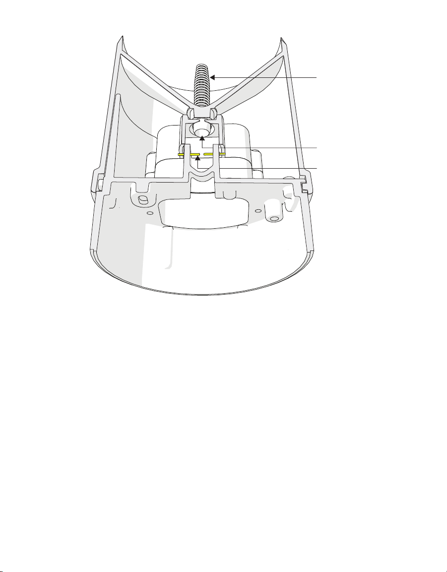
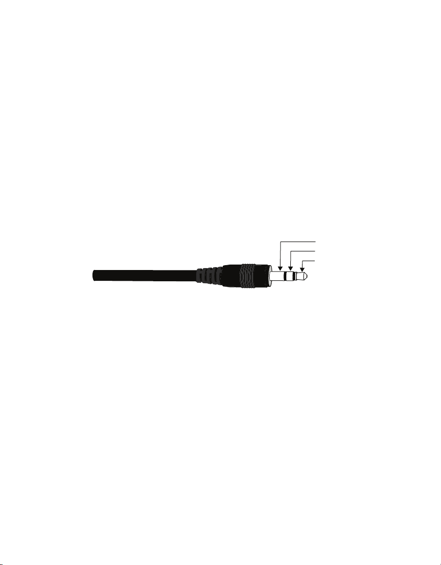
The standard ATMOS41 comes with a 3.5-mm stereo plug connector (Figure1) to facilitate
easy connection with METER loggers. ATMOS41 sensors may be ordered with stripped and
tinned (pigtail) lead wires for use with screw terminals when connecting to some third-party
loggers (Section 2.2.2).
Ground
Data
Power
3.5-mm stereo plug connector wiring
The ATMOS41 comes standard with a 5-m cable. It may be purchased with custom cable
lengths for an additional fee (on a per-meter basis). METER has successfully tested digital
communication on cable lengths up to 1,000 m (3,200 ft). This option eliminates the need
for splicing the cable (a possible failure point). However, the maximum recommended
length is 75 m.
2.2.1 CONNECT TO METER DATA LOGGER
The ATMOS41 works seamlessly with ZENTRA or EM60 data loggers. Check the METER
downloads webpage (metergroup.com/downloads) for the most recent data logger
firmware. Logger configuration may be done using either ZENTRA Utility (desktop and
mobile application) or ZENTRA Cloud (web-based application for cell-enabled ZENTRA
data loggers).
NOTE: This system will not work with legacy data loggers (Decagon Em5, Em5B, Em50,Em50R, Em50G).
1. Plug the 3.5-mm stereo plug connector into one of the sensor ports on the logger.
2. Once the ATMOS41 has been connected to a ZENTRA or EM60 data logger, using the
appropriate software application, congure the chosen logger port for the ATMOS41.
3. Set the measurement interval.

5
ATMOS 41
NOTE:
EM60 data logger may have significant impact on battery life. At times or in regions with plentiful sunshine, the
solar panel should provide ample charge and this should not be an issue. During the winter or periods of extended
heavy clouds, the solar panel may not provide enough charging current to keep the system running with multiple
2.2.2
The ATMOS41 can be used with non-METER (third party) data loggers. Refer to the third-
party logger manual for details on logger communications, power supply, and ground ports.
The ATMOS41 can be ordered with stripped and tinned (pigtail) connecting wires for use with
screw terminals. Connect the ATMOS41 wires to the data logger as illustrated in Figure2 and
Figure3, with the power supply wire (brown) connected to the excitation, the digital out
wire (orange) to a digital input, and the bare ground wire to ground. The ATMOS41 Integrator
Guide gives detailed instructions on connecting the weather station to non-METER loggers.
Ground (bare)
Data (orange)
Power (brown)
Pigtail wiring
NOTE:
digital out is red, and the bare wire is ground.
Switched
3.6–15 VDC
Digital
In
Data Logger
G
Data
(orange)
Ground
(bare)
Power
(brown)
Wiring diagram
NOTE:
Scientific data loggers,power the sensors off a 12 V port.
If the ATMOS41 has a standard 3.5-mm stereo plug connector and will be connected to a
non-METER data logger, please use one of the following two options when connecting to
a non-METER data logger.

6
OPERATION
Option 1
1. Clip off the plug on the sensor cable.
2. Strip and tin the wires.
3. Wire it directly into the data logger.
This option has the advantage of creating a direct connection with no chance of the sensor
becoming unplugged. However, it then cannot be easily used in the future with a METER
readout unit or data logger.
Option 2
Obtain an adapter cable from METER.
The adapter cable has a connector for the female stereo plug connector on one end and
three wires (or pigtail adapter) for connection to a data logger on the other end. The stripped
and tinned adapter cable wires have the same termination as in Figure3; the brown wire is
excitation, the orange is output, and the bare wire is ground.
NOTE: Secure the 3.5-mm stereo plug connector to the pigtail adapter connections to ensure the sensor does not
become disconnected during use.

7
ATMOS 41
3. SYSTEM
This section describes the ATMOS 41 All-in-One Weather Station system.
3.1 SPECIFICATIONS
MEASUREMENT SPECIFICATIONS
Solar Radiation
Range: 0–1750 W/m2
Resolution: 1 W/m2
Accuracy: ±5% of measurement typical
Precipitation
Range: 0–400 mm/h
Resolution: 0.017 mm
Accuracy: ±5% of measurement from 0 to 50 mm/h
Vapor Pressure
Range: 0–47 kPa
Resolution: 0.01 kPa
Accuracy: Varies with temperature and humidity,
±0.2 kPa typical below 40 °C
Relative Humidity
Range: 0–100%
Resolution: 0.1%
Accuracy: Varies with temperature and humidity, ±3% RH typical
Air Temperature
Range: –50 to 60 °C
Resolution: 0.1 °C
Accuracy: ±0.6 °C
Humidity Sensor Temperature
Range: –40 to 50 °C
Resolution: 0.1 °C
Accuracy: ±1.0 °C

8
SYSTEM
Barometric Pressure
Range: 50–110 kPa
Resolution: 0.01 kPa
Accuracy: ±0.1 kPa
Horizontal Wind Speed
Range: 0–30 m/s
Resolution: 0.01 m/s
Accuracy: The greater of 0.3 m/s or 3% of measurement
Wind Gust
Range: 0–30 m/s
Resolution: 0.01 m/s
Accuracy: The greater of 0.3 m/s or 3% of measurement
Wind Direction
Range: 0°–359°
Resolution: 1°
Accuracy: ±5°
Tilt
Range: –90° to 90°
Resolution: 0.1°
Accuracy: ±1°
Lightning Strike Count
Range: 0–65,535 strikes
Resolution: 1 strike
Accuracy: Variable with distance, >25% detection at <10 km typical
Lightning Average Distance
Range: 0–40 km
Resolution: 3 km
Accuracy: Variable

9
ATMOS 41
PHYSICAL CHARACTERISTICS
Dimensions
Diameter 10 cm (3.94 in)
Height 34 cm (13.39 in), includes rain gauge lter
Cable Length
5 m (standard)
75 m (maximum custom cable length for additional cost)
NOTE: Contact Customer Support if a nonstandard cable length is needed.
Connector Types
3.5-mm stereo plug connector or stripped and tinned wires
ELECTRICAL AND TIMING CHARACTERISTICS
Supply Voltage (VCC to GND)
Minimum 3.6 VDC continuous
Typical NA
Maximum 15.0 VDC continuous
Digital Input Voltage (logic high)
Minimum 2.8 V
Typical 3.0 V
Maximum 5.5 V
Digital Input Voltage (logic low)
Minimum –0.3 V
Typical 0.0 V
Maximum 0.8 V
Digital Output Voltage (logic high)
Minimum NA
Typical 3.6 V
Maximum NA

10
SYSTEM
Power Line Slew Rate
Minimum 1.0 V/ms
Typical NA
Maximum NA
Current Drain (during measurement)
Minimum 0.2 mA
Typical 8.0 mA
Maximum 33.0 mA
Current Drain (while asleep)
Minimum 0.2 mA
Typical 0.3 mA
Maximum 0.4 mA
Operating Temperature Range
Minimum –50 °C
Typical NA
Maximum 60 °C
Power Up Time (SDI Ready)—aRx! Commands
Minimum NA
Typical 10 s
Maximum NA
Power Up Time (SDI Ready)—Other Commands
Minimum NA
Typical 800 ms
Maximum NA
Measurement Duration
Minimum NA
Typical 110 ms
Maximum 3,000 ms

11
ATMOS 41
COMPLIANCE
Manufactured under ISO 9001:2015
EM ISO/IEC 17050:2010 (CE Mark)
3.2 PYRANOMETER
Solar radiation is measured by a pyranometer that is integrated into the lip of the rain gauge
funnel at the top of the ATMOS 41. Designed, manufactured, and calibrated by experts at
Apogee Instruments, the miniature pyranometer uses a silicon-cell sensor to measure the
total incoming (direct and diffuse) solar radiation. A carefully developed cosine-correcting
head ensures accurate readings regardless of sun angle, while the painstakingly researched
optical filter material balances cost and performance to ensure the silicon-cell provides
good accuracy regardless of temperature or sensor age. Silicon-cell sensors have excellent
response time to changing radiation conditions and acceptable sensitivity across the solar
spectrum (Figure4), which make them perfect for use on the ATMOS 41.
Spectral Response
1.2
1.1
1.0
0.9
0.8
0.7
0.6
0.5
0.4
0.3
0.2
0.1
0.0
300 400 500 600 700 800 900 1000 1100 1200
Weighting Factors
Wavelength [nm]
Spectral response estimate of Apogee silicon-cell pyranometers
Spectral response was estimated by multiplying the spectral response of the photodiode,
diffuser, and adhesive. Spectral response measurements of diffuser and adhesive were
made with a spectrometer, and spectral response data for the photodiode were obtained
from the manufacturer.

12
SYSTEM
Leveling the ATMOS 41 is particularly important for accurate solar radiation measurements.
Out of level, the pyranometer will overestimate some portions of the day while under-
estimating others. Ensure accurate solar radiation measurements by carefully leveling the
ATMOS 41 at installation. Bird droppings and other soiling of the domed sensor surface will
cause serious errors in pyranometer measurements. Check the sensor regularly to make sure
it is clean and check data often to identify possible problems. Isopropyl (rubbing) alcohol and
a Q-tip work well for cleaning the sensor area. Microfiber bags work well, too. Do NOT use an
abrasive cloth on the sensor surface, as it will scratch.
The pyranometer is factory calibrated and the sensor-specific calibration value can be found
on the interior of the rain funnel. This factor has already been added into the ATMOS41 so
there is no need to do anything with it. In the event that this value is needed, it can be found
by taking the funnel off the base and checking underneath. Follow the steps in Section3.5 to
remove the funnel.
When powered on, the ATMOS41 measures the solar radiation once every 10 s and
records the instantaneous values. When queried, the ATMOS41 outputs the average of the
instantaneous measurements since the last query.
3.3 ANEMOMETER
The space underneath the rain gauge is where the ATMOS41 measures wind speed.
Ultrasonic signals emitted from transducers at right angles to each other bounce off
the porous sintered glass plate (Figure5) and back up to the opposite sensor. The
speed ofsound is affected by the wind, and the wind speed is calculated by measuring
differences in the time it takes for sound to travel back and forth between sensors
(Section3.11.1).
When powered on, the ATMOS41 measures the wind speed and direction once every 10 s and
records the instantaneous wind vector components. When queried, the ATMOS41 outputs
the average of the instantaneous measurements since the last query for wind speed and
direction and the maximum instantaneous wind speed value for wind gust.
Splash
guard
Sintered
glass plate
Anemometer

13
ATMOS 41
3.4 VAPOR PRESSURE/RELATIVE HUMIDITY SENSOR
The vapor pressure sensor (Figure6) on the ATMOS41 is located behind the circular Teflon
™
screen in the same housing as the sonic transducers. The Teflon screen protects the sensor
from liquid water and dust while allowing water vapor to freely pass to the sensor and
equilibrate with air vapor pressure. The sensor measures relative humidity and temperature
in addition to computing vapor pressure.
Teon screen
Vapor pressure sensor
If the relative humidity of the air is desired, it can be computed using Equation 1.
Equation 1
RHr ,air =
e
a
e
s
( T
air
)
where ea is the vapor pressure of the air, from the ATMOS41, and es(Tair ) is saturation vapor
pressure at the air temperature given by the ATMOS41.
The saturation vapor pressure is calculated using the Magnus-Tetens equation (Equation 2)
with the following coefficients described by Buck (1981).
Equation 2
esTair =a exp
bT
air
c+T
air
Water a= 0.611 kPa b= 17.502 c
=
240.97 °C Tair
= Temperature in °C
Ice a= 0.611 kPa b= 21.87 c
=
265.5 °C Tair
= Temperature in °C

14
SYSTEM
Unlike relative humidity, vapor pressure does not depend on temperature, and is generally
conservative over time and space. The vapor pressure of the atmosphere near the relative
humidity sensor is the same as the vapor pressure at the relative humidity sensor, even if the
relative humidity sensor is not at the same temperature as the atmosphere. Additionally, it
is the vapor pressure of the atmosphere (not RH) that controls the rate of vapor phase water
transport (e.g., evaporation, transpiration, and distribution of water vapor). Therefore, vapor
pressure is a much more useful measure of atmospheric moisture than relative humidity.
When powered on, the ATMOS41 measures the vapor pressure once every 60 s and
records the instantaneous values. When queried, the ATMOS41 outputs the average of the
instantaneous measurements since the last query.
3.5 RAIN GAUGE
The ATMOS41 contains a 9.31-cm diameter rain gauge. During rain events, the flared hole
(Figure7) forms the rain into drops that pass by the drip counter. The spring (Figure7) acts
as a filter to keep out large particles but still allows enough flow so water does not back
up. Gold pins (Figure7) measure each drop of rain. Because the flared hole forms a drop of
a known size, the ATMOS41 counts the drops and calculate the water volume. As the rain
intensity increases, the drops become smaller, but the ATMOS41 firmware contains an
algorithm to automatically compensate for drop size as the rain increases.
When powered on, the ATMOS41 counts water drops continuously and adds each drop to an
accumulated total. When queried, the ATMOS41 outputs the total rainfall (in mm) that has
accumulated since the last query.
IMPORTANT: ±2 degrees of dead level (0, 0) in both the X and Y directions
to accurately measure rainfall. If not within this range, drops from the flared hole can miss the gold electrodes entirely.

15
ATMOS 41
Spring
Flared hole
Gold electrodes
Rain gauge
The rain gauge locks in place using two pegs on the side of the rain gauge funnel. Follow the
steps below to get inside the rain gauge.
1. Line up the lock/unlock graphic located on the side of the rain gauge funnel with the notch
on the interface plate.
2. Press the rain gauge funnel down against the spring and turn counter clockwise until it
clicks in place.
ATTENTION: UNPLUG THE PYRANOMETER CONNECTOR INSIDE THE FUNNEL BEFORE FULLY REMOVING THE FUNNEL.
3. Before replacing the cover, be sure to reattach the pyranometer connector by mating the
two halves of the white connector and seating rmly together until the tabs lock.
NOTE: The connector is polar so it can only mate in one orientation.
4. Check to be sure the downspout screen is in place on the water exit downspout
(Figure12). This keeps bugs out of the interior of the sensor.

16
SYSTEM
3.6 TEMPERATURE SENSOR
The ATMOS41 temperature measurement (Figure8) is made in the center of the
anemometer area where a small stainless steel needle containing a tiny temperature
sensor (thermistor) extends from the middle of the four sonic transducers in the center of
the anemometer. Unlike most air temperature measurements, the weather station sensor
is not covered with louvered plates to protect from solar heating. Instead, it sits in open air,
susceptible to solar heating of the instrument body. However, the ATMOS41 calculates the
air temperature accurately because solar radiation and the wind speed are known. These
are the two main parameters that determine the error between measured air temperature
and the actual air temperature. Therefore, it is possible to solve the energy balance to
get what the actual temperature should be based on the solar load of the body and the
convective cooling of that temperature sensor.
When powered on, the ATMOS41 measures the air temperature once every 10 s and
records the instantaneous values. When queried, the ATMOS41 outputs the average of the
instantaneous measurements since the last query.
NOTE:
Temperature sensor
Temperature sensor
3.7 LIGHTNING SENSOR
The lightning sensor acts much like an AM radio. During a thunderstorm, the crack of the
lightning disrupts the AM signal. The integrated circuit inside the sensor listens for this
crackle, and when the sensor detects a disturbance, it registers the time of and distance
(intensity of signal) to the strike. The sensor outputs the total number of strikes and average
distance to these strikes in the measurement period. The sensitivity of the lightning sensor
can be adjusted using the ProCheck (Section 3.8).
Other manuals for ATMOS 41
5
Table of contents
Other METER Weather Station manuals
Popular Weather Station manuals by other brands

Sharper Image
Sharper Image 206085 owner's guide

Bresser
Bresser 4Cast 95-01100 instruction manual

Bresser
Bresser 70-02510 instruction manual

La Crosse Technology
La Crosse Technology WS-7047TWC instruction manual

jbc
jbc LB 3200 instruction manual

La Crosse Technology
La Crosse Technology 308-1414Bv3 Setup guide

PEHA
PEHA 940 WES Installation and operating instruction

La Crosse Technology
La Crosse Technology Wireless Rain Station Setup guide

Bresser
Bresser Quadro Individio instruction manual

All Weather Inc
All Weather Inc 1190 user manual

La Crosse Technology
La Crosse Technology WS-1913IT Quick setup manual

Eurochron
Eurochron EFWS 801 operating instructions