Proxess PX10110003 User manual

C-Series
Service manual

ii
Proxess C-Series Service Manual
CONTENTS
INTRODUCTION 1-1
Certifications and standards 1-1
Documentation package 1-2
Technical support 1-2
FUNCTIONS AND PARTS 2-1
Lock functions 2-1
Function descriptions 2-1
Lock parts 2-3
Exploded view of parts 2-3
Parts list 2-3
Trim parts 2-5
MAINTENANCE 3-1
Maintenance tools 3-1
Replacing levers 3-1
TROUBLESHOOTING 4-1
Troubleshooting hardware 4-1
Troubleshooting software 4-1
INSTALLATION MANUAL 5-1
Cylindrical installation instructions

iii
Proxess C-Series Service Manual
INTRODUCTION
The Proxess C-Series Service Manual contains important information to assist you in maintaining your C-Series
Lock.
CERTIFICATIONS AND STANDARDS
ANSI/BHMA A156.25 (Indoor/Outdoor)
ANSI/BHMA A156.2 Grade 1
UL 294
ULC S319 PDR
UL10C Positive Pressure Rated
UL10B Neutral Pressure Rated
FCC Part 15
ADA Compliant
RoHS
Industry Canada (IC)
ETSI EN 300 330-1
ETSI EN 301 489-1
ETSI EN 301 489-3
CENELEC EN 61000-6-3
IEC61000-4-2 ESD Immunity
CENELEC EN 50130-4
1-1

iv
Proxess C-Series Service Manual
DOCUMENTATION PACKAGE
Document Title Doc. No.
Cylindrical Installation Manual PXM1001
User Manual PXM1002
Software Manual PXM1003
TECHNICAL SUPPORT
•Your first source for technical answers is this C Series Service Manual.
•If you are not able to find an answer to your question in this manual, contact your local Proxess
Representative.
•If you do not know your local Proxess Representative, contact the Customer Service Department at
Proxess –303-317-6656.
1-2
v
Proxess C-Series Service Manual
FUNCTIONS AND PARTS LISTS
LOCK FUNCTIONS
FUNCTION DESCRIPTIONS
All locks are supplied in Construction Mode as a default and are meant to be reprogrammed at customer site
prior to installation.
CC –Construction Mode: Factory default setting. Upon first programming of the lock, the lock will switch to
Program Lock Function. A system ID (GUID) will be set by the factory allowing all credentials assigned to the
site system access until the lock is reprogrammed.
Inside lever is always unlocked for single action egress.
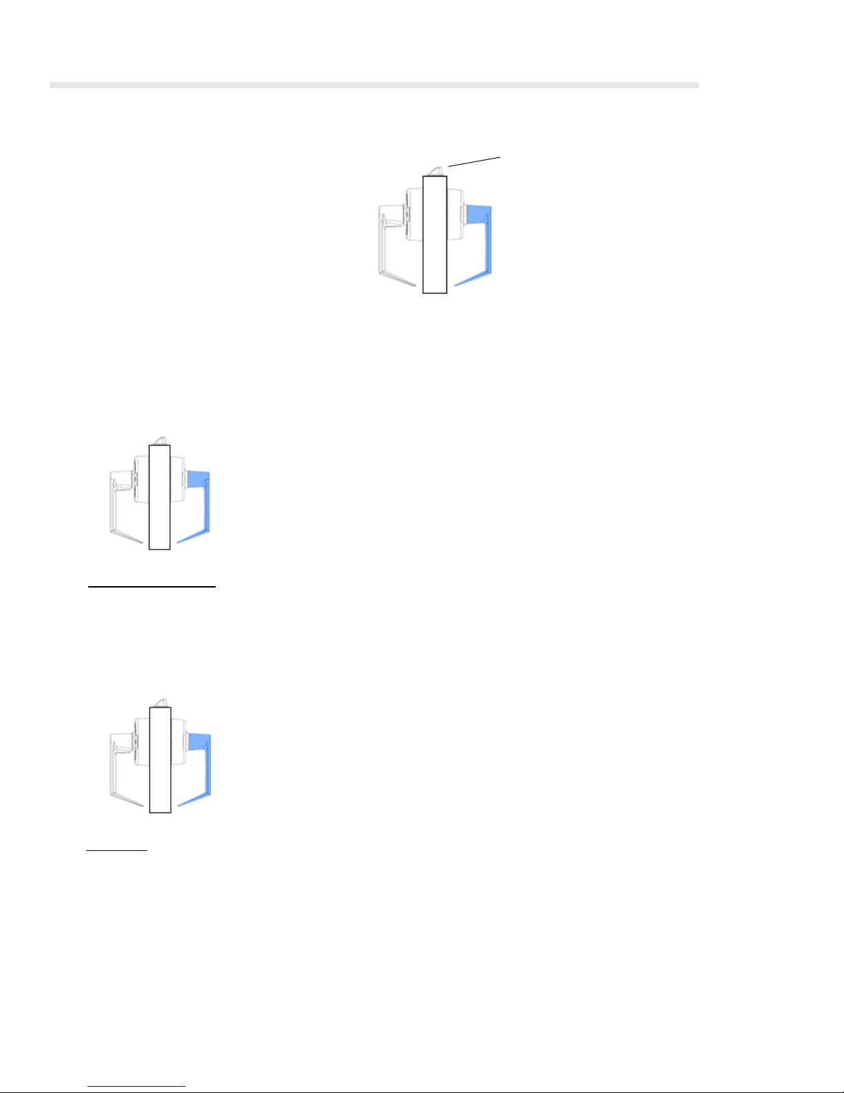
ST –Standard: Lock is normally in the locked state. Upon presentation of a valid credential, lock will
momentarily unlock to allow entry then revert to the normally locked state.
Inside lever is always unlocked for single action egress.
Inside
Outside
Latch
Shading indicates that
the lever is locked.
View looking down at
the top of the door
2-1

vi
Proxess C-Series Service Manual
XC –Emergency Classroom: (Presentation of a valid credential will unlock the lock for a user-selectable period
of time. This function will support unlock schedules and toggle to allow locking and unlocking when presented
with a valid credential. Furthermore, a BLE (Bluetooth) interface is supplied on the interior trim of the lock. The
BLE interface is paired with an active fob which enables a teacher or user to place a lock in lockdown state
from a distance up to 100 feet directly from the fob.
An emergency override credential allows designated administrators or emergency personnel access when
exterior lever is in locked position.
Inside lever is always unlocked for single action egress.
2-2
vii
Proxess C-Series Service Manual
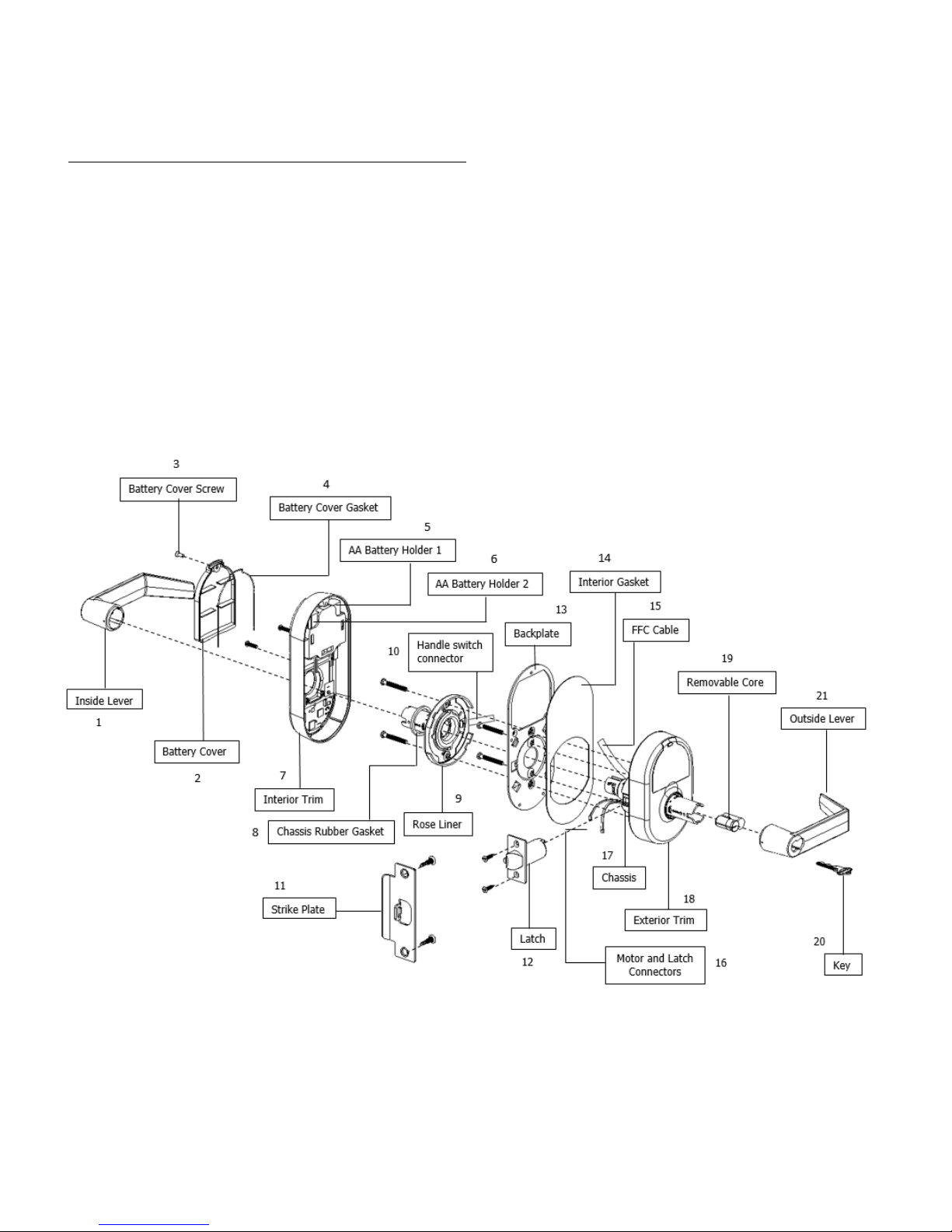
PART AND PARTS LISTS
ST FUNCTION CHASSIS - STANDARD
Item Part No. Item Part.No
1PX10110001 12 PX10120005
2PX10110003 13 PX10110010
3PX10110004 14 PX10110011
4PX10110005 15 PX10110013
5PX10110006 16 PX10110014
6PX10110007 17 PX10120001
7PX10110002 18 PX10100002
8PX10110008 19 PX10100003
9PX10110016 20 PX10100004
10 PX10110012 21 PX10100001
11 PX10120002
2-3
viii
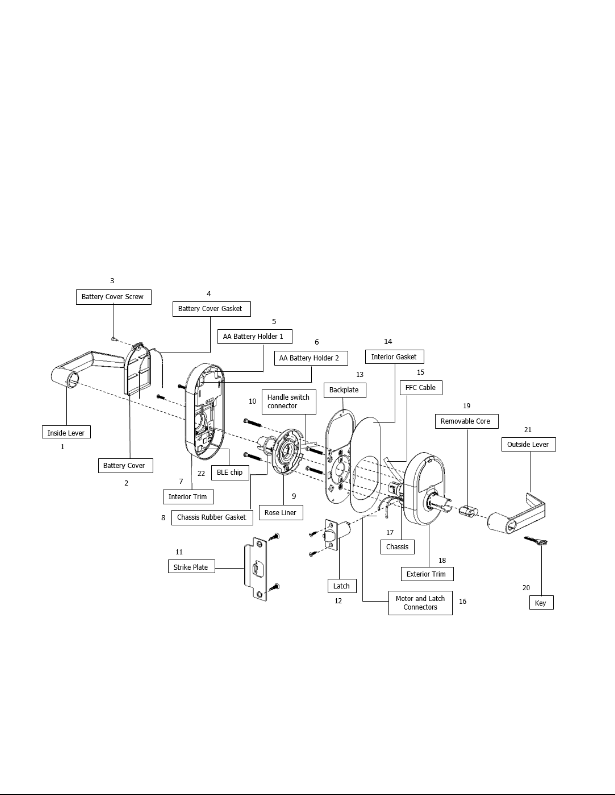
Proxess C-Series Service Manual
XC FUNCTION CHASSIS - EMERGENCY CLASSROOM
Item Part No. Item Part.No
1PX10110001 12 PX10120005
2PX10110003 13 PX10110010
3PX10110004 14 PX10110011
4PX10110005 15 PX10110013
5PX10110006 16 PX10110014
6PX10110007 17 PX10120001
7PX10110002 18 PX10100002
8PX10110008 19 PX10100003
9PX10110016 20 PX10100004
10 PX10110012 21 PX10100001
11 PX10120002 22 PX10110015
2-4
ix
Proxess C-Series Service Manual
TRIM PARTS
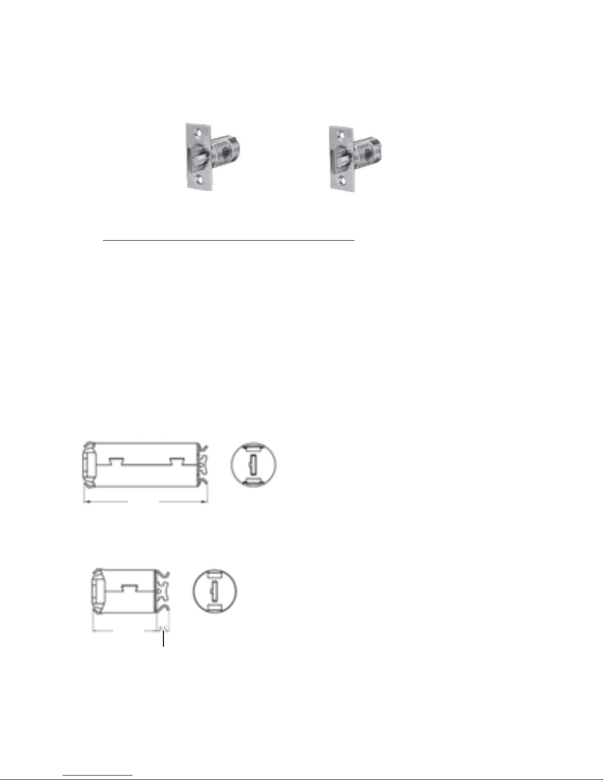
LATCH BACKSETS
Item Part. No. Description
B1 PX10120006 Standard 2 ¾"
B2 PX10120007 2 ⅜"
LATCHES
Optional latch extensions
B1
B2
2-5
2¾" (70mm) latch + 57mm extension tube for 5"
(127mm) requirement
2⅜" (60mm) latch + 35mm extension tube for 3¾"
(95mm) requirement
61.1
32.4
4.3
x
Proxess C-Series Service Manual
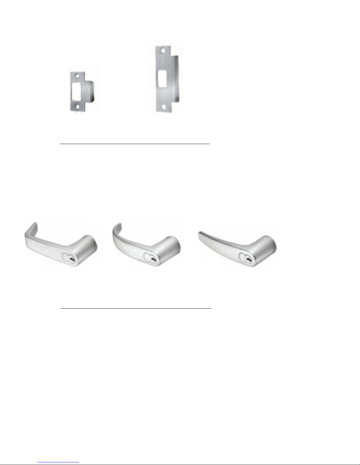
STRIKE PLATES
Item Part. No. Description
S1 PX10120002 Standard 2 ¾" strike
S2 PX10120003 ANSI 4 ⅞" strike
LEVERS
Item Part. No. Description
6 PX10120005A Angled Return; (most common lever)
7 PX10120005C Curved Return
9 PX10120005N Curved No Return; (no lever return)
6
8
9
2-6
S1
S2

xi
Proxess C-Series Service Manual
MAINTENANCE
TOOLS FOR MAINTENANCE
REPLACING LEVERS
TO REMOVE THE LEVER:
1. If removing the exterior lever, first remove the removable core by inserting the control key and turning
it 15 degrees clockwise, then pull out the removable core and key.
2. Insert the pin of the lever release tool into the small hole at the base of the shaft on the lever.
3. Push in and then slide the lever off the sleeve of the lever shaft.
Lever Release Tool
Philips Screwdriver, #2
Lever release tool
Lever shaft
3-1

xii
Proxess C-Series Service Manual
TO REPLACE THE LEVER:
1. Position the lever so the handle points towards the door hinges.
2. Slide the lever onto the lock and push firmly until it is seated.
3. If replacing the exterior lever, reinstall the removable core by aligning the throw member (forked
prongs) within the lock chassis and then sliding the core back in place. Turn the control key 15 degrees
counterclockwise and remove the key.
4. Turn both levers to make sure they retract the latch if the door is unlocked.
3-2

xiii
Proxess C-Series Service Manual
TROUBLESHOOTING
TROUBLESHOOTING HARDWARE
The following table illustrates possible causes and solutions for common problems after installing the lock
hardware.
Problem Possible Reason Solution
LED does not blink on exterior Batteries were replaced and the Synchronize the lock with the
when presenting a credential lock was not synchronized with MPD and try the credential
the MPD again
Batteries are dead and need to Replace the batteries,
Be replaced synchronize the lock with the
MPD and try the credential
again
The 10 pin connector FFC cable Remove the interior trim and
was not connected properly ensure that cable is seated
correctly
MPD does not connect to the lock Bluetooth is not enabled on the Enable Bluetooth in Settings
MPD
Batteries are at low voltage Replace the batteries and try the
MPD again.
Lock does not go into Lock Down When configuring the door with Close the door, connect the MPD,
when programmed for Privacy the MPD “Set Door Closed” was select “Set Door Closed”, try Lock
not selected. Down again.
The 4 pin connector FFC cable Remove the interior trim and
was not connected completely ensure that cable is seated correctly
4-1

xiv
Proxess C-Series Service Manual
INSTALLATION INSTRUCTIONS
The following pages contain the Installation Manual for the C-series Cylindrical Lock.
xv
Proxess C-Series Service Manual
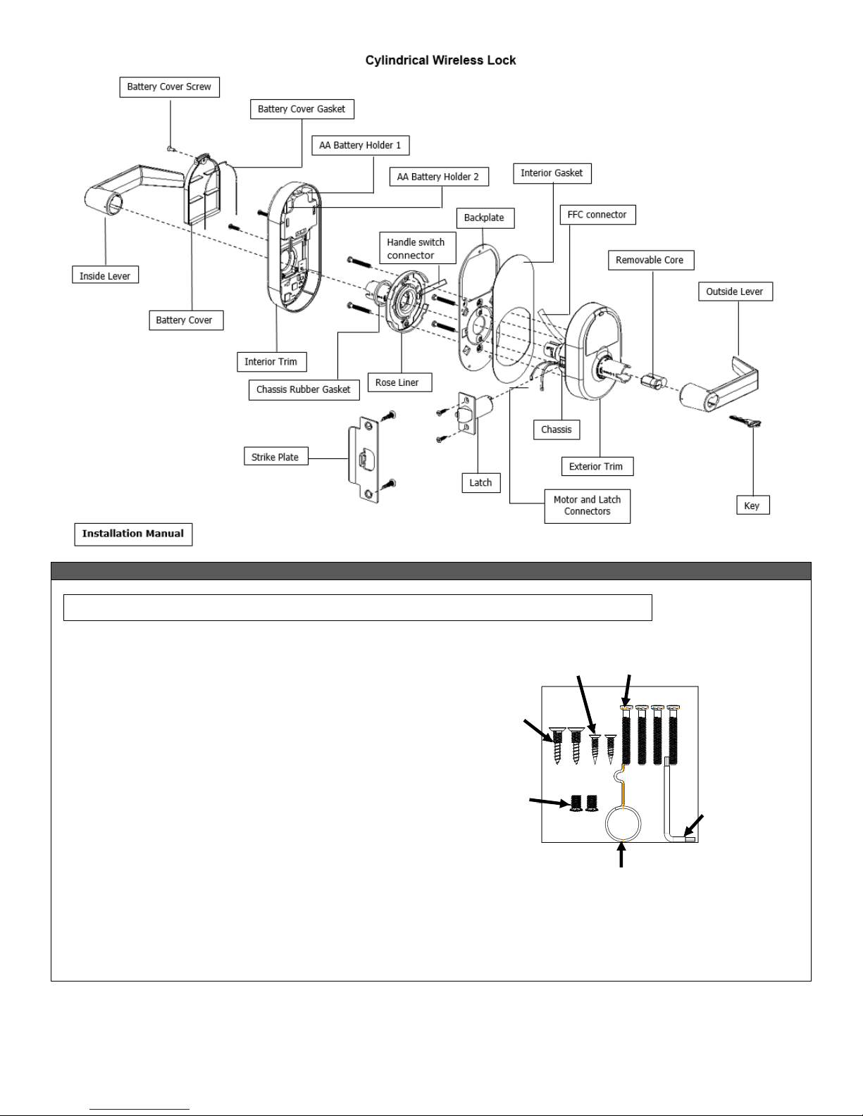
A. CHECKLIST (4 each AA Batteries Included)
Parts List: Each Proxess C-Series lockset includes
•Exterior lock assembly (include housing, lever and cylinder drive unit)
•Interior lock assembly
•Installation Instructions
•Door Preparation Template
•Hardware box includes:
-Electrified lock chassis assembly
-Interior lever + Steel ring
-Exterior rose/chassis mounting plate
-Interior rose/chassis mounting plate
-Latch bolt with deadlock
-2 Keys
-ASA Strike
-Screw Pack includes:
▪(SB1) Hager mounting screws M5 x 38mm x4pcs
▪(SB2) Flat head tapping screws #8x3/4" x2pcs
▪(SB3) Flat head tapping screws #12-24 x 18mm x2pcs
▪(SB4) Lever release tool
▪(SB5) Hager mounting screws M6 x 10mm x2pcs (optional)
▪(SB6) Trox wrench
(SB1)
(SB2)
(SB3)
(SB4)
(SB5)
(SB6)
FOR DOOR AND FRAME PREPARATION INSTRUCTIONS, SEE APPENDIX A OR GO TO PROXESS.COM
(SB3)
(SB5)
(SB2)
(SB1)
(SB6)
(SB4)
)
xvi
Proxess C-Series Service Manual
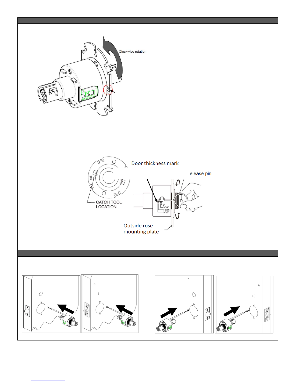
B. ADJUST FOR DOOR THICKNESS
Install exterior rose mounting plate onto the lock body by rotating it clockwise. Pay attention to the installation direction of mounting
plate’s anti-rotation tabs, they should be pointed toward the door.
1. Please follow the steps below:
a. Rotate exterior rose mounting plate toward cylindrical chassis.
b. Put the lever release tool into the allocated position of exterior rose mounting plate per the illustration below.
c. Rotate exterior rose mounting plate to door thickness by using the lever release tool.
C. LOCK HANDING
1. Determine the hand of your door. The product is set up for Right Hand by default.
Anti-Rotation Tabs on the rose
mounting plate
Lever Release Tool
Right Hand Door
Left Hand Door
Right Hand
Reverse Door
Left Hand
Reverse Door
PLEASE NOTE THAT THE LOCK BODY COMES
PRE-SET TO ACCOMMODATE A 1¾ INCH DOOR

xvii
Proxess C-Series Service Manual
STEP 1
STEP 4
Install the latch in the door. The latch tube prongs should
project into the chassis hole.
To re-hand the lock chassis, begin by first removing the rubber
gasket from the back of the lock, and removing the FFC cable
from the cable slot.
Unscrew the backplate to remove the lock chassis and turn it
180 degrees to accommodate the hand of the door.
Replace the lock chassis and reroute the FFC cable into the cable
slot. Screw on the backplate and replace the rubber gasket.
STEP 2
Install the strike plate, checking to make sure that the position
of the deadlocking plunger is aligned against the strike plate.
STEP 3
Ensure the cable from the exterior board is properly routed
through the cylindrical lock chassis by first inserting one edge,
then pressing the other into the cable slot.
1
2
3
4
5
Rotate 180 degrees
Re-handed lock chassis to
accommodate left handed door

xviii
Proxess C-Series Service Manual
STEP 5
STEP 7
Slide the lock chassis through the chassis hole in the door,
ensuring that the chassis engages the latch.
Disconnect the handle switch connector from the interior
board.* Place the outside rose liner on the interior back plate
and screw in. Ensure that both the handle switch connector and
FFC connector sit in the side channels around the rose liner
while the motor and latch connectors are fed through the rose
liner.
* TO CONNECT AND DISCONNECT THE 4 AND 10-
PIN CONNECTORS
To connect the pin connectors (FFC and handle switch), begin
by pushing up the black cowl.
Then insert the cable with the wires facing away from you and
push until you hear a click.
Push the black cowl back down to secure the connector.
To disconnect the connectors, push up on the black cowl and
pull out the cable.
STEP 6
Place the back plate on the interior of the door with the upper
and lower screws near the chassis. Wire the cable and wires as
shown:
Motor and latch
connectors
FFC connector
Handle switch
connector
1
2
3

xix
Proxess C-Series Service Manual
STEP 8
STEP 10
Slide the rubber gasket over the chassis sleeve.
Place the motor wire on top of the handle assembly when
installing the interior trim onto the back plate. Also ensure that
the 10-pin FFC and 4-pin handle switch connectors run along the
sides of the interior trim. Screw the interior trim onto the back
plate using the two screws on the right and left of the battery
hole.
STEP 9
Connect the motor connector first, followed by the latch
connector. Then connect the 4-pin handle switch connector.
Connect the FFC cable last.
Note: The battery cable should already be pre-connected.
STEP 11
Install the four AA batteries, beginning with the outer two.
After the batteries are properly installed, the lock should beep
once and the motor should run. The lock is then locked.
Handle switch
connector
FFC connector
Battery connector
Motor connector
Latch connector
1
2
3
4
Motor wire should
run along here.
Both the FFC and hand switch connectors
should run along the sides of the trim.
Insert first
Insert last
xx
Proxess C-Series Service Manual
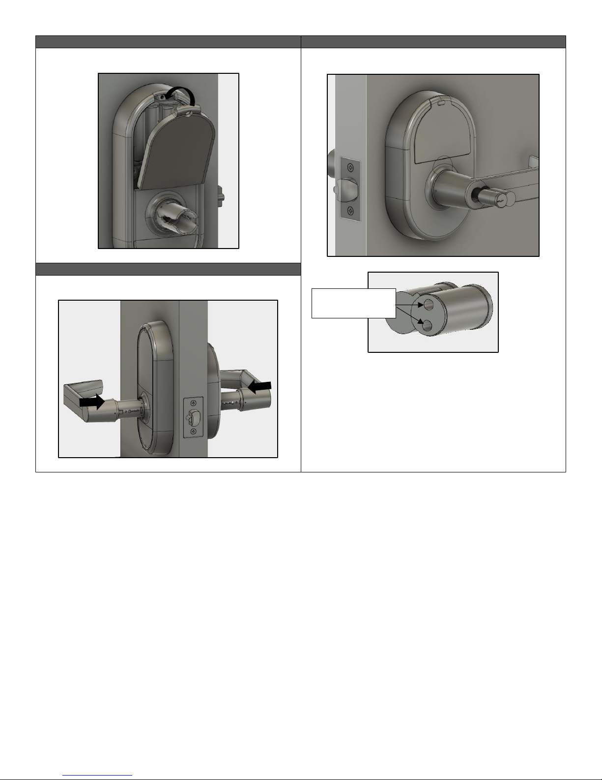
STEP 12
STEP 14
Screw the battery cover onto the trim.
Install the removable core.
Once the removable core is aligned with the forked pin in the
lock, insert the control key and turn clockwise 15 degrees to
retract the catch, then insert the core into the lever. Turn the
control key back counterclockwise 15 degrees to engage the
core and remove the key.
STEP 13
Install the levers onto the outside and inside of the door.
Align with prongs
of forked pin
This manual suits for next models
27
Table of contents


