Proxim Tsunami Multipoint Version 2.0 User manual

-~
ARTISAN
®
~I
TECHNOLOGY
GROUP
Your definitive source
for
quality
pre-owned
equipment.
Artisan Technology
Group
Full-service,
independent
repair
center
with
experienced
engineers
and
technicians
on staff.
We
buy
your
excess,
underutilized,
and
idle
equipment
along
with
credit
for
buybacks
and
trade-ins
.
Custom
engineering
so
your
equipment
works
exactly as
you
specify.
•
Critical
and
expedited
services
•
Leasing
/
Rentals/
Demos
• In
stock/
Ready-to-ship
•
!TAR-certified
secure
asset
solutions
Expert
team
ITrust
guarantee
I
100%
satisfaction
All
tr
ademarks,
br
a
nd
names, a
nd
br
a
nd
s a
pp
earing here
in
are
th
e property of
th
e
ir
r
es
pecti
ve
ow
ner
s.
Find the Proxim Tsunami WLH-A07T at our website: Click HERE

Subscriber Unit Quick Install Guide
Tsunami Multipoint Version 2.0
Part Number 67318r1
Artisan Technology Group - Quality Instrumentation ... Guaranteed | (888) 88-SOURCE | www.artisantg.com

Tsunami Multipoint SU Quick Install Guide
The maximum room ambient temperature (Tmra) for
this product is –33 to +65 degrees Centigrade. The
ambient temperature range for the power supply is 0-
55 degrees Centigrade. Consideration should be given
to installing this equipment in an environment
compatible with the Tmra.
Second Edition, December 2003
IMPORTANT SAFETY INSTRUCTIONS
Review the Tsunami Multipoint Installation Manual and
Reference Manual for important installation instructions
BEFORE you attempt to install this product. Equipment is suitable for mounting on concrete or
other noncombustible surface only.
This product is to be installed, used, and maintained by
experienced telecommunications personnel only. Do not remove or alter the Marking label provided on
this product.
This product has been evaluated to the U.S. and
Canadian (Bi-National) Standard for Safety of
Information Technology Equipment, Including Electrical
Business Equipment, CAN/CSA C22.2, No. 950-985 *
UL 1950, Third Edition, including revisions through
revision date March 1, 1998, which are based on the
Fourth Amendment to IEC 950, Second Edition. In
addition, this product was also evaluated to the
applicable requirements in UL 1950, Annex NAE.
Contents
INTRODUCTION.............................................................. 2
Before You Begin .................................................3
INSTALLING CONFIGURATION SOFTWARE............... 3
Step 1: Install the Subscriber Utility.....................3
Step 2: Install BSU Configuration Software......... 3
WARNING! This unit is intended for installation in
accordance with Articles 110-18, 110-26, and 110-
27 of the United States National Electric Code
ANSI/NFPA 70; and per Articles of the Canadian
National Electric Code.
Step 3: Upgrade Firmware ..................................4
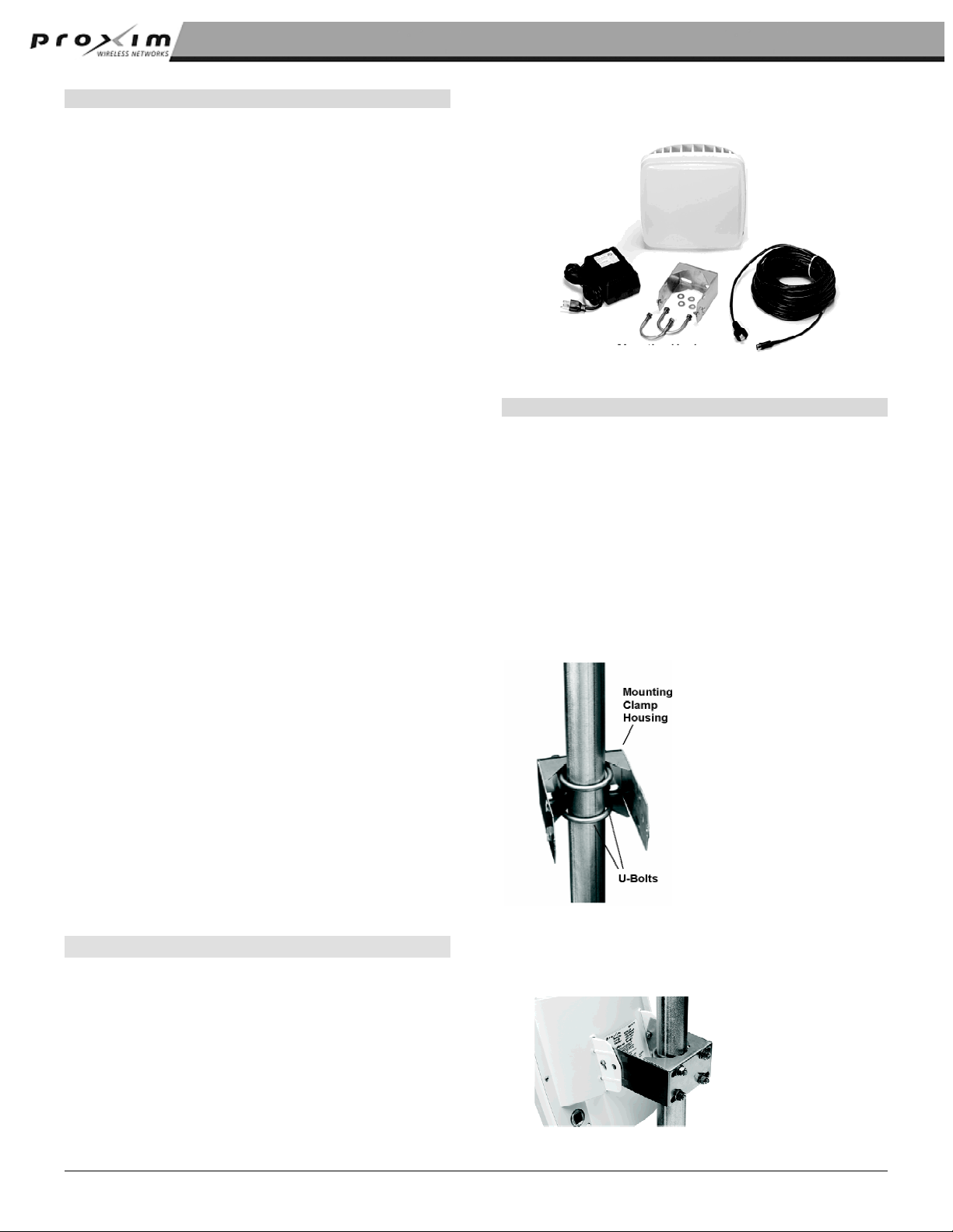
DEPLOYING THE SUBSCRIBER UNIT (SU).................. 4
Step 1: Mounting the Subscriber Unit..................4
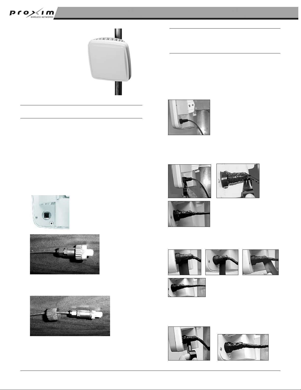
Step 2: Connecting Cables..................................5
Step 3: Aiming the SU .........................................6
This equipment should be installed in accordance with
Article 810 of the United States National Electrical
Code.
Step 4: Displaying Link Status Information..........7
Step 5: Confirming Network Activity .................... 7
SYSTEM REQUIREMENTS FOR VERSION 2.0............. 8
Equipment is to be used with, and powered by, the
power supply provided only. TECHNICAL SUPPORT .................................................. 8
Lightning surge protection is provided by the power
supply included with this product while powered.
Objects may contact hazardous energy parts that could
result in a risk of fire or personal injury.
Introduction
The following documents comprise the Tsunami
Multipoint documentation set.
A 15-Amp circuit breaker is required at the power
source.
▪
▪
▪
▪
The Tsunami Multipoint BSU Quick Install provides
just enough information for the experienced
professional to install the Tsunami Multipoint BSU.
WARNING! This equipment is to be earthed. See
the Installation Manual for the proper grounding
method. Use the provided 10AWG copper earthing
conductor, or equivalent, for this purpose. The Tsunami Multipoint SU Quick Install provides
just enough information for the experienced
professional to install the Tsunami Multipoint SU.
Do not connect or disconnect the power cable to the
equipment when the power supply is plugged in an AC
outlet. The Tsunami Multipoint Installation Guide provides
detailed installation information for the less
experienced professional to install and initially
configure the Tsunami Multipoint system. If you
are uncertain about any of the procedures in the
Quick Install, refer to this document on the
Tsunami Multipoint CD.
Only trained personnel should perform servicing of this
product. Do not disassemble this product. By opening
or removing any covers, you may expose yourself to
hazardous energy parts. Incorrect re-assembly of this
product can cause a malfunction and/or electrical
shock when the unit is subsequently used.
Do not insert any objects of any shape or size inside
this product while powered. Objects may contact
hazardous energy parts that could result in a risk of fire
or personal injury.
The Tsunami Multipoint Reference Manual
provides conceptual, advanced configuration, and
command reference information about the Tsunami
Multipoint system.
Do not spill any liquids of any kind on or inside this
product. This device must be professionally installed!
Copyright © 2003 Proxim Corporation. All Rights Reserved. 2
Artisan Technology Group - Quality Instrumentation ... Guaranteed | (888) 88-SOURCE | www.artisantg.com

Tsunami Multipoint SU Quick Install Guide
2. Insert the Tsunami Multipoint CD (provided with
the product) into the computer’s CD-ROM drive
and open the CD’s config software folder.
BEFORE YOU BEGIN
Make sure you verify that the MAC Address on the SU
being installed has been entered into the BSU’s access
table prior to installing. You should also record: Note: If the PC has Microsoft IIS running, disable it
before running the Subscriber Utility.
▪
▪
▪
▪
▪
▪
▪
The S/N and MAC address of the SU being
installed and the site name. Keep the information
in a safe place. The MAC address is required to
be entered into the BSU database to establish a
link and the Serial Number is required for support
from Proxim and is available only from the label of
the unit.
3. Double-click susetup.htm (or use a Web browser
to open the file).
4. Click to place a checkmark in the box next to the
Include VM in download option to install Java
Virtual Machine (VM).
The Channel ( 4, 5 or 6 ) of the BSU to which the
SU is to connect as well as the Frequency ( A, B,
C, D, or E).
Note: You need not add VM if your computer already
has an appropriate version of VM installed.
The modulation rate of the BSU to which the SU is
to connect (20, 30, 40 or 60 Mbps).
5. Click the Start Installer for Windows button to
begin the software installation.
The mode of operation of the BSU to which the SU
is to connect (Bridging or Routing)
6. Follow the on-screen instructions to install the
software.
The Access Mode of the BSU to which the SU is to
connect (Restricted or Open).
Click Done when the installation is finished to close the
installer.
Whether VLAN tagging is enabled on the BSU or
SU. STEP 2: INSTALL BSU CONFIGURATION
SOFTWARE
Whether VoIP Mode is enabled. To install the BSU/SU Console:
If the BSU is set to Routing mode and Restricted, you
must use at least one of the five IP addresses allowed
under this configuration for a device connected to the
SU.
1. From your server’s Windows Explorer root
directory, double-click on the BSU folder; then
double-click on the Install icon (or install.exe).
2. Two windows open simultaneously:
InstallAnywhere Web Installer — Microsoft
Internet Explorer (in disabled mode)
superimposed by Security Warning (in enabled
mode).
You must install the Subscriber Utility Software as well
as the Base Station Configuration Software on your
PC.
Installing Configuration Software
Click the Yes button on the Security Warning
window to close this window and view the Base
Station Configuration Software window.
You must install the Subscriber Utility software in order
to install the SU. The Subscriber Utility software is
used in the antenna pointing process.
3. Click Download 15.7M to download the Tsunami
Multipoint Base Station configuration software and
Java VM; click Download 2.7M to download the
Tsunami Multipoint Base Station configuration
software without Java VM.
The BSU Configuration Software is also required in the
antenna pointing process—after aiming, the SU
performs a net entry to the BSU and the BSU assigns
a new IP address to the SU. The BSU Configuration
Software is also required for enhanced SU diagnostics.
4. After the download completes, double-click on
BS.exe to begin installation.
STEP 1: INSTALL THE SUBSCRIBER UTILITY
5. When the Tsunami Multipoint Base Station
Configuration Software Introduction window is
displayed; click Next.
To install the Subscriber Utility software:
1. Identify the computer on which you will run the
Subscriber Utility. 6. Follow the on-screen instructions to install the
software.
Note: See “System Requirements” for operating
system and hardware requirements. When the Install Complete window is displayed, click
on Done to return to the Web Installer window; then
close the Web Installer window.
Copyright © 2003 Proxim Corporation. All Rights Reserved. 3
Artisan Technology Group - Quality Instrumentation ... Guaranteed | (888) 88-SOURCE | www.artisantg.com

Tsunami Multipoint SU Quick Install Guide
Unpack the following from the contents of the shipping
box:
STEP 3: UPGRADE FIRMWARE
Proxim recommends that all equipment be upgraded to
Firmware Version 2.0 (PMP_SU_release2-0.mot). If
the SU is new from the factory, it is preloaded with the
current SU Firmware Version.
Subscribe
r
Unit
CAT5 Cable
Powe
r
Suppl
y
The method for upgrading SU equipment from previous
versions to Version 2.0 using the local download
method follows. This method describes attaching a PC
with the Base Station Configuration Software installed
to the SU.
Firmware can be downloaded to the SU by the over-
the-air method once the SU has established
connection to the BSU. This method is described in
detail in Appendix B of the Tsunami Multipoint
Installation Manual (“Firmware Downloads”).
Mounting Hardware
STEP 1: MOUNTING THE SUBSCRIBER UNIT
Local Download to SUs
The outdoor component of the Subscriber Unit is
designed to directly mount to a pole. Using the
supplied U-bolts, you can mount the SU to a 1-1/4 inch
to 1-3/4 inch pole (outside diameter). Using optional
mounting brackets, you can mount the SU to a wall or
other flat surface.
You can use this method to upgrade SUs that have not
been deployed or have failed to successfully download
using the remote over-the-air procedure. Using this
procedure, individual SUs are upgraded through their
Ethernet/Power cable.
This procedure requires the Tsunami Multipoint Base
Station Configuration Software application be loaded
on the PC attached to the SU (SU 1.,4 or 1.5 Console).
The window label appears as “Tsunami Multipoint
Subscriber Utility Configuration Software.”
1. Insert the two U-bolts into the mounting clamp
housing and attach the two #5/16 nuts and 5/16
flat washers.
2. Slide the mounting clamp housing/pole clamp
assembly down the pole.
To download locally to an SU:
1. From the Subscriber Utility 1.4 or 1.5 console,
select the Download menu.
2. Select Local Firmware.
3. From the Look In search field, choose the binary
file to be downloaded (PMP_SU_release2-0.mot)
from the appropriate directory and click Select.
The download requires about 2 minutes. Once the
download is complete, the banner indicating
Version 2.0 is displayed.
If the download does not complete successfully, as
indicated by a checksum mismatch or a failure to
reboot, cycle power to the SU and repeat, starting at
step 1. Squeeze the sides of the mounting clamp housing
and slide it inside the flange protruding from the
back of the SU until the pins extend into the holes
on the side of the flange.
Deploying the Subscriber Unit (SU)
Make sure to record the serial number and site at
which the SU is installed. The serial number is
required to obtain support from Proxim and is available
only from the label on the back of the SU.
Copyright © 2003 Proxim Corporation. All Rights Reserved. 4
Artisan Technology Group - Quality Instrumentation ... Guaranteed | (888) 88-SOURCE | www.artisantg.com

Tsunami Multipoint SU Quick Install Guide
3. Insert the two #10-32
screws in the sides
of the mounting
clamp housing/pole
clamp assembly and
loosely attach the
two #10-32 nuts.
Note: Be sure the Tsunami Multipoint Subscriber Unit
connector is properly “contacted” or the unit
may fail; you should hear a “click” when
installing the cable connector to its chassis.
4. After you aim the SU
(see “Aiming the
SU”), tighten the two
#10-32 screws and
nuts to secure the SU in position.
3. Weatherproof the connection with waterproof butyl
tape, as shown in the following photos:
The first photo depicts the connector before
weatherproofing. You will add three layers of tape;
one strip of butyl tape and two strips of electrician’s
tape are required.
1
Note: Complete “Step 2. Connecting Cables” before
aiming the SU.
STEP 2: CONNECTING CABLES
The following steps detail how to connect the cables
between the radio, power adapter, and your network.
First, wrap the connector using the first strip of
electrician’s tape, as shown in photos 2, 3, and 4.
This serves as a base for the butyl tape, letting you
remove the butyl tape easily when necessary.
For each radio/power adapter set, perform these steps:
1. Insert the RJ-45 connector on the CAT5 cable into
the RJ-45 port on the back of the SU until the
locking tab clicks; slide the Woodhead body over
the RJ-45 connector until it is fully seated. Hand-
tighten the Woodhead connector; do not use the
wrench to tighten the connector.
3
2
4
4
RJ-45 Connector
Next, in the same manner, apply a layer of butyl
tape over the electrician’s tape, as shown in
photos 5 – 8.
Woodhead
Cover
Placed over
RJ-45
Connector
5 6 7
8
2. Tighten the end nut to seal the connector to the
housing, and tighten the gland to seal the
assembly to the cable.
8
End nut Finally, apply a layer of black electrician’s tape
over the butyl tape for further protection, as shown
in photos 9 and 10; the butyl tape alone is not UV
protected.
End nut
seated on
RJ-45
connector
9 10
Copyright © 2003 Proxim Corporation. All Rights Reserved. 5
Artisan Technology Group - Quality Instrumentation ... Guaranteed | (888) 88-SOURCE | www.artisantg.com

Tsunami Multipoint SU Quick Install Guide
3. Choose the desired frequency plan and operating
frequency. The factory default is the 4-channel
frequency plan and frequency Auto. Selecting a
specific frequency forces the SU to search for a
BSU only on that specific frequency. Selecting
Auto lets the SU search all frequencies in the plan.
4. Connect a standard CAT5 cable (not supplied) to
the RJ-45 port on the power adapter. Connect the
other end of the cable to a switch or hub on your
network or directly to a PC.
To directly connect the radio to a PC, use a
straight-through Ethernet cable between the
network interface card in the PC and the RJ-45
port on the power adapter. Use a cross-over
Ethernet cable if connecting the power adapter to
a switch or a hub.
WARNING!
The maximum length of the CAT5 cable allowed
between the radio unit and the power adapter is 75
meters. The total length between the radio unit and
PC, switch, or other network device, including the
cabling from the radio unit and the power adapter
and the cable from the power adapter to the network
device, is 100 m.
5. If you are connected to a switch or a hub, connect
a PC to the same switch or hub to which you
connected the radio. Each PC is used to configure
and control its associated radio.
6. Connect the power adapter to a grounded AC
power source. The radio will emit a small chirp to
indicate that it is receiving power. 4. Click on the Installation sub-tab and turn on the
Audible Signal-Strength Indicator (if not already
set to On).
Note: To ensure proper grounding, use the hole
on the back of each SU and the provided
grounding screws to attach a ground wire
to each radio. Use wire grounding
techniques in accordance with your local
electrical codes.
STEP 3: AIMING THE SU
The SU is shipped from the factory in aiming mode
(with Channel 4and Frequency Auto) so that you can
install and aim it without having to first run the
Subscriber Utility. You must run the Subscriber Utility,
however, to take the SU out of aiming mode in order to
establish a link with the BSU.
1. The PC and the SU must be members of the same
IP subnet to communicate properly. On the PC
that has the Subscriber Utility installed, change the
IP address for its Ethernet card to 192.168.20.xx
with a 255.255.255.0 subnet mask, where xx can
be any available number between 1 and 254.
Proxim recommends using 10 to avoid using the
same IP address as the BSU or SU). You can run
the Multi-BSU configuration software to verify the
IP address of the SU that is displayed in the tab.
2. Launch the Subscriber Utility.
Copyright © 2003 Proxim Corporation. All Rights Reserved. 6
Artisan Technology Group - Quality Instrumentation ... Guaranteed | (888) 88-SOURCE | www.artisantg.com

Tsunami Multipoint SU Quick Install Guide
5. Click Save Settings and Install Subscriber Unit
to launch the aiming tool.
On the computer that is connected to the SU,
launch the Multi-BSU Configuration Software.
Once this software connects to the attached SU,
the “Configuration Software” banner changes to
“Subscriber Configuration Software.” At this point,
the “Connection 1:” tab indicates the new IP
address of the SU.
6. Slowly adjust the position of the SU until you have
maximized the strength of the radio signal.
º The SU beeps after it has detected a signal
from the BSU. The beeps increase in
frequency as the strength of the signal
received from the BSU increases. You must now change the IP address of the PC that is
running the Subscriber Utility software to a new
address within the same subnet as that of the SU.
º The Receive Signal Quality indicator within the
Subscriber Utility’s Installation window reports
the strength of the radio signal. STEP 5: CONFIRMING NETWORK ACTIVITY
7. Click OK to close the aiming tool. Because of the learning bridge filter of the Tsunami
Multipoint system, Proxim recommends you do not
move a computer that was behind one end of the link
to the other end of the link.
If you have left the Base Station Configuration
Software running on the computer connected to the
BSU, a notification is displayed once the SU has
successfully joined the network. The learning bridge filter learns local hosts connected
to the Ethernet port (up to 16 at the BSU and the SU)
and prevents traffic from being sent to the wireless port
for those hosts. This is based upon the MAC address
of the host. For this reason, Proxim recommends that
you test the Tsunami Mutlipoint with two PCs, one
behind the BSU and one behind the SU.
STEP 4: DISPLAYING LINK STATUS
INFORMATION
1. The Status window displays the current
information at the SU, as well as information about
the link between the BSU and the local SU. To
display the Status window select the Status tab. You can clear the learning bridge filter on the BSU or
SU by first disconnecting the PC and then rebooting
the BSU or SU before moving the PC to the other side.
Attempt to ping from a computer on the SU side of the
network to a computer on the BSU side of the network.
The BSU and SU must have different IP addresses to
do this. If the BSU and SU are configured with the
same IP address, the local unit responds to the ping
(that is, if the BSU and SU have the same IP address
and you ping the BSU from a host connected to the
SU, the SU responds to the ping).
If the ping tests are unsuccessful, attempt the
following:
2. If all of the fields within the Status window are
blank (except for Operating Status where you
read “ODU not connected”), this most likely
means that the BSU has assigned a new IP
address to the SU that is not within the same
subnet as the IP that you have assigned to the NIC
card on the PC running the Subscriber Utility.
1. Check all IP and computer configurations (for
example, if you attempt to ping the BSU from the
SU configuration computer and the BSU and SU’s
are in separate networks, you must have the
configuration computer’s gateway set to the SU for
the ping to work.)
2. Adjust the network’s IP settings, if necessary, to
achieve IP connectivity.
3. If the Status window is similar to the previous
figure, proceed to “Confirming Network Activity.” If
you receive an “ODU not connected” message in
the Operating Status field, perform the following.
If this procedure fails, see “Chapter 4. System
Diagnostics and Operating Tips” in the Tsunami
Multipoint Installation Manual. This chapter contains
information about running system diagnostics to
ensure the equipment is operating as expected .
Further information can be found in “Appendix A.
Troubleshooting” in the Tsunami Multipoint Reference
Manual.
Copyright © 2003 Proxim Corporation. All Rights Reserved. 7
Artisan Technology Group - Quality Instrumentation ... Guaranteed | (888) 88-SOURCE | www.artisantg.com

Tsunami Multipoint SU Quick Install Guide
System Requirements for Version 2.0
Hardware Multimedia PC with a Pentium 200 MHz
or higher processor (300 MHz
recommended).
Operating
System
Microsoft Windows® 98, NT 4.0, Me,
2000, XP.
Java 2 VM SDK or runtime (1.2.2_12 or later,
1.3.1_03 is provided)
Memory 64 MB for Windows® 95/98 or
Windows® Me; 128 MB for Windows®
NT 4.0 workstation, Windows® 2000
Professional, or Windows® XP
Professional (256 MB RAM is
recommended).
Hard Drive 2 GB hard disk with up to 250 MB of
available hard-disk space.
ROM Drive Double speed (2x) or faster CD-ROM /
DVD-ROM.
NIC 10/100 Mbps NIC with RJ-45 input.
Input
Devices
Standard IBM-PC compatible 101-key
style keyboard, PS2 or USB compatible
mouse, or a compatible pointing device.
Monitor Super VGA 16-bit or higher monitor
supporting 800 x 600 screen resolution;
coordinated video driver for installed
video card; VGA not supported.
Graphics
Card
PCI, AGP, or on-board graphics card
supporting 16-bit 640 x 480 video
resolution or higher.
Video Driver Must support 16-bit color.
Browser Microsoft Internet Explorer 5.0 software
or later (6.0 recommended); other
browsers also supported.
Optional
Hardware
16-bit sound card with speakers or
headphones for audible alarm; 6 foot
power strip with power surge protection.
Optional
Software
Microsoft Personal Web Server, Internet
Information Server (IIS), or Apache
1.3.x for over the Internet console
installation.
Technical Support
If you are having a problem using a Tsunami Multipoint
and cannot resolve it with the information in “Appendix
A. Troubleshooting” in the Tsunami Multipoint
Reference Manual, gather the following information
and contact Proxim Technical Support:
▪
▪
▪
▪
▪
▪
▪
▪
▪
▪
What kind of network are you using?
What were you doing when the error occurred?
What error message did you see?
Can you reproduce the problem?
Be sure to:
Note the serial number of the product before
installation. Keep this information in a safe place.
The serial number is required to obtain support and
can be found only on the back of the unit.
Obtain an RMA number before sending any
equipment to Proxim for repair.
Have the following logs from the affected equipment
before calling Technical Support:
SUlog1
SUlog2
BSUlog (for each affected SU)
uplber, berlog (for each affected SU)
Access Knowledgebase:
Ask a Wireless WAN Product question and get an
express response: WANsupport@proxim.com
E-mail Technical Support:
To receive E-mail technical support, be sure to include
the serial number of the product or products in
question. We will be unable to respond to your inquiry
without this information.
Call Technical Support:
Toll Free +1-866-674-6626 or +1-408-542-5390
Hours: 6:00 a.m. to 5:00 p.m. M-F Pacific Time
Copyright © 2003 Proxim Corporation. All Rights Reserved. 8
Artisan Technology Group - Quality Instrumentation ... Guaranteed | (888) 88-SOURCE | www.artisantg.com

Artisan
Technology
Group
is
an independent supplier
of
quality pre-owned equipment
Gold-standard
solutions
Extend the life
of
your
critical industrial,
commercial, and military systems
with
our
superior service and support.
We
buy
equipment
Planning to
upgrade
your current
equipment? Have surplus equipment taking
up shelf space? We'll give it a
new
home.
Learn
more!
Visit us at artisantg.com for more info
on price quotes, drivers, technical
specifications, manuals, and documentation.
Artisan Scientific
Corporation
dba
Artisan
Technology
Group
is
not
an affiliate,
representative,
or
authorized
distributor
for
any
manufacturer
listed herein.
We're here to make your life easier.
How
can
we
help you today?
(217)
352-9330
Isales@artisantg.com Iartisantg.com
Other manuals for Tsunami Multipoint Version 2.0
2
Table of contents
Other Proxim Accessories manuals
Popular Accessories manuals by other brands

Rocket Fish
Rocket Fish RF-HTS205 Garantie de l’équipement connecté

Heath Zenith
Heath Zenith 595-5684-09 owner's manual

Silvercrest
Silvercrest SPBL 6000 A1 Operation and safety notes

PowerWalker
PowerWalker BlueWalker quick guide

Sport Tech
Sport Tech PT300 manual

Lenord, Bauer
Lenord, Bauer GEL 2449 operating instructions