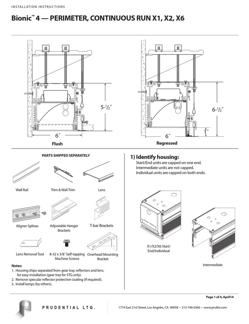
Prudential Bionic CONTINUOUS RUN X3 User manual

PRULITE.COM 213.746.0360
Prudential Ltg. reserves the right to change design specications or materials without notice. Please visit prulite.com for most current data.
© 2015 All rights reserved – All products manufactured at: Prudential Ltg. 1774 E. 21st Street, Los Angeles, CA 90058
WARNING: Ground fixture in accordance with local and national electrical codes. Failure to do so may result in serious personal injury.
61 of
LED Bionic |Recessed Linear
4˝ Slot
INSTALLATION INSTRUCTIONS
CONTINUOUS RUN X3, X7
LED
CROSS SECTIONS
FLUSH
5˝
5⁄˝
4⁄˝
Aperture
5⁄˝
Ceiling Opening
5⁄˝: X3
6⁄˝: X7
CEILING OPENING
LIGHT POCKET WALL TO WALL
ROW
LENGTH + ¾˝ + ½˝
REG1
6⁄˝
1˝
LENS
WALL RAIL
LENS REMOVAL TOOL 8-32_X_3_8_HWH_SELF_TAP
ADJUSTABLE HANGER BRACKETS T-BAR BRACKETS OVERHEAD MOUNTING BRACKET
ALIGNER SPLINES “L” Trim
LENS
WALL RAIL
LENS REMOVAL TOOL 8-32_X_3_8_HWH_SELF_TAP
ADJUSTABLE HANGER BRACKETS T-BAR BRACKETS OVERHEAD MOUNTING BRACKET
ALIGNER SPLINES “L” Trim
LENS
WALL RAIL
LENS REMOVAL TOOL 8-32_X_3_8_HWH_SELF_TAP
ADJUSTABLE HANGER BRACKETS T-BAR BRACKETS OVERHEAD MOUNTING BRACKET
ALIGNER SPLINES “L” Trim
LIGHT POCKET:
START/END/INDIVIDUAL INTERMEDIATE WALL-TO-WALL: START/END
Start/end xtures are capped on one end.
Intermediate xtures are not capped
Individual xtures are capped on both ends.
IDENTIFYING HOUSING
PARTS (SHIPPED SEPARATELY) PART NO. DESCRIPTION
—Lens
100-00019-14 8-32 x ⁄˝ Self-Tapping Screw
100-00191-02 Adjustable Hanger Bracket
100-00066-02 Aligner Spline
82484 Lens Removal Tool
—T-Bar Trim
—“U”Trim
Remove specular reector protective coating (if required).
07-02-2020

PRULITE.COM 213.746.0360
Prudential Ltg. reserves the right to change design specications or materials without notice. Please visit prulite.com for most current data.
© 2015 All rights reserved – All products manufactured at: Prudential Ltg. 1774 E. 21st Street, Los Angeles, CA 90058
WARNING: Ground fixture in accordance with local and national electrical codes. Failure to do so may result in serious personal injury.
62 of
LED Bionic |Recessed Linear
4˝ Slot
INSTALLATION INSTRUCTIONS
CONTINUOUS RUN X3, X7
INSTALLATION
LENS
WALL RAIL
LENS REMOVAL TOOL 8-32_X_3_8_HWH_SELF_TAP
ADJUSTABLE HANGER BRACKETS T-BAR BRACKETS OVERHEAD MOUNTING BRACKET
ALIGNER SPLINES “L” Trim
2)1) Install aligner splines on housing.
— 2 per joint on Seamless,
Flush and Reg1.
— 4 per joint on Reg3.
Secure xture to structure with wire and all
thread. (Multiple options.)
Mounting Detail (1) Housing Detail for ¼-20
℄
X
Y Y
¼˝ Wiring K.O.
MOUNTING CONVERSION CHART:
* From Centerline
X = 2’ 3’ 4’ 5’ 6’ 7’ 8’
Y =* 9˝ 15˝ 21˝ 27˝ 33˝ 39˝ 45˝
℄
LENS
WALL RAIL
LENS REMOVAL TOOL 8-32_X_3_8_HWH_SELF_TAP
ADJUSTABLE HANGER BRACKETS T-BAR BRACKETS OVERHEAD MOUNTING BRACKET
ALIGNER SPLINES “L” Trim
3)
LENS
WALL RAIL
LENS REMOVAL TOOL 8-32_X_3_8_HWH_SELF_TAP
ADJUSTABLE HANGER BRACKETS T-BAR BRACKETS OVERHEAD MOUNTING BRACKET
ALIGNER SPLINES “L” Trim
4)
If additional holes are drilled in top plate for ¼-20 all thread,
support with additional #8 screws at closest locations to
new holes.
Fasten inside joiner brackets on row mounted housings.
8-32 x ⁄˝
Self-tapping Screws
8-32 x ¼˝
Machine Screws
BY OTHERS
WARNING: Failure to properly install top screws will void warranty
OPTION A.
Insert ¼-20 all-thread. Can protrude
into housing no more than ⁄˝
OPTION B.
Hang ¼-20 all-thread or wire from
adjustable hanger bracket
LENS
WALL RAIL
LENS REMOVAL TOOL 8-32_X_3_8_HWH_SELF_TAP
ADJUSTABLE HANGER BRACKETS T-BAR BRACKETS OVERHEAD MOUNTING BRACKET
ALIGNER SPLINES “L” Trim
5) Slide and tighten aligner splines over joints.
LENS
WALL RAIL
LENS REMOVAL TOOL 8-32_X_3_8_HWH_SELF_TAP
ADJUSTABLE HANGER BRACKETS T-BAR BRACKETS OVERHEAD MOUNTING BRACKET
ALIGNER SPLINES “L” Trim
LENS
WALL RAIL
LENS REMOVAL TOOL 8-32_X_3_8_HWH_SELF_TAP
ADJUSTABLE HANGER BRACKETS T-BAR BRACKETS OVERHEAD MOUNTING BRACKET
ALIGNER SPLINES “L” Trim
6) 7)
Measure and install
backer anges (X7BF)
at appropriate height.
(Required for X7,
except on pre-
framed sots.)
Install drywall and
self-tapping drywall
screws into X7BF.
Backer ange can
install with up to 2⁄˝
thick hard ceiling
Drywall should be
ush with housing
Drywall screws (by others)
must be ush with drywall
Option to
hang drywall
from backer
ange
SHIPPING STRAPS
07-02-2020

PRULITE.COM 213.746.0360
Prudential Ltg. reserves the right to change design specications or materials without notice. Please visit prulite.com for most current data.
© 2015 All rights reserved – All products manufactured at: Prudential Ltg. 1774 E. 21st Street, Los Angeles, CA 90058
WARNING: Ground fixture in accordance with local and national electrical codes. Failure to do so may result in serious personal injury.
63 of
LED Bionic |Recessed Linear
4˝ Slot
INSTALLATION INSTRUCTIONS
CONTINUOUS RUN X3, X7
LENS
WALL RAIL
LENS REMOVAL TOOL 8-32_X_3_8_HWH_SELF_TAP
ADJUSTABLE HANGER BRACKETS T-BAR BRACKETS OVERHEAD MOUNTING BRACKET
ALIGNER SPLINES “L” Trim
8) 9)
Uninstall reector
where wiring xture
through top knockouts.
Make electrical
connections and
reinstall reector. Safety Cable
Reector
LENS
WALL RAIL
LENS REMOVAL TOOL 8-32_X_3_8_HWH_SELF_TAP
ADJUSTABLE HANGER BRACKETS T-BAR BRACKETS OVERHEAD MOUNTING BRACKET
ALIGNER SPLINES “L” Trim
10) Install trim and secure
to housing only.
X7 — PROCEED TO STEP 11
X3 — SKIP TO STEP 15
Trim
LENS
WALL RAIL
LENS REMOVAL TOOL 8-32_X_3_8_HWH_SELF_TAP
ADJUSTABLE HANGER BRACKETS T-BAR BRACKETS OVERHEAD MOUNTING BRACKET
ALIGNER SPLINES “L” Trim
13)
Remove shipping straps /
aperture guides.
MUST TEST lens ts in ALL (X7)
applications before mud-in.
LENS
WALL RAIL
LENS REMOVAL TOOL 8-32_X_3_8_HWH_SELF_TAP
ADJUSTABLE HANGER BRACKETS T-BAR BRACKETS OVERHEAD MOUNTING BRACKET
ALIGNER SPLINES “L” Trim
12) Install screws through
backer ange (Recess.)
Secure trim to drywall using
drywall screws (by others).
LENS
WALL RAIL
LENS REMOVAL TOOL 8-32_X_3_8_HWH_SELF_TAP
TRIM WALL — X3
TRIM WALL — X7
ADJUSTABLE HANGER BRACKETS T-BAR BRACKETS OVERHEAD MOUNTING BRACKET
ALIGNER SPLINES
NOTE: Leave ⁄˝ air
gap at each end of run.
Table saw or chop saw with
a 80T blade recommended.
16)15) Install lensing, cut
last piece to t.
Install “U” end trims and
straight trims, cut last
piece to t.
Tape and mud-in to trim (X7).
SHIPPING STRAPS
LENS
WALL RAIL
LENS REMOVAL TOOL 8-32_X_3_8_HWH_SELF_TAP
ADJUSTABLE HANGER BRACKETS T-BAR BRACKETS OVERHEAD MOUNTING BRACKET
ALIGNER SPLINES “L” Trim
11) Re-install shipping
straps / aperture
guides. (X7 only).
SHIPPING STRAPS
C8 CORNERS:
Aligner
Spline
Blocking
(BY OTHERS)
2 x 6 Stud
Required
(BY OTHERS)
5⁄” *
Finshed Wall Opening
5 Housing˝
5¾˝ *
Stud Aperture
* Keep nished wall opening and studs aperture as specied in the wall cross section.
LENS
WALL RAIL
LENS REMOVAL TOOL 8-32_X_3_8_HWH_SELF_TAP
ADJUSTABLE HANGER BRACKETS T-BAR BRACKETS OVERHEAD MOUNTING BRACKET
ALIGNER SPLINES “L” Trim
14 a)
14 b)
SHIPPING STRAPS
Tape and
mud-in to
trim edge
(X7)
Remove shipping
straps / aperture
guides.
07-02-2020

PRULITE.COM 213.746.0360
Prudential Ltg. reserves the right to change design specications or materials without notice. Please visit prulite.com for most current data.
© 2015 All rights reserved – All products manufactured at: Prudential Ltg. 1774 E. 21st Street, Los Angeles, CA 90058
WARNING: Ground fixture in accordance with local and national electrical codes. Failure to do so may result in serious personal injury.
64 of
LED Bionic |Recessed Linear
4˝ Slot
INSTALLATION INSTRUCTIONS
CONTINUOUS RUN X3, X7
C8I:CORNERS INSTALLATION
2)
3)
1)
INSTALL ADJACENT SECTIONS:
Continue installing straight sections
from the corner moving outward
according to row layouts in job drawing.
Pull sections together with aligner
joiner brackets, and secure to studs.
Pull electrical power into xture.
Conrm spacing at ends
of rows, ensuring that
there is enough room for
installation of nish trim.
INSTALL DRYWALL:
Install drywall, leaving a 5-⁄˝
opening for trim.
INSTALL C8I CORNER:
After removing reectors and LED trays
but leaving shipping straps, install C8
corner in a wall with a 5⁄˝ stud clearance.
Secure with screws through back of corner
into blocking between studs (by others).
MINIMUM DISTANCES:
X3 Light Pocket = ¾˝
X7 Light Pocket = 1½˝
Wall-to-Wall = ½˝
5-⁄˝
5-⁄˝
4-⁄˝
Ceiling Fixture
C8I Corner
Wall Fixture
DRYWALLDRYWALL
5-⁄˝
4-⁄˝
ALIGNER
JOINER
BRACKET
Studs
Studs
5-⁄˝5-⁄˝
BLOCKING
07-02-2020

PRULITE.COM 213.746.0360
Prudential Ltg. reserves the right to change design specications or materials without notice. Please visit prulite.com for most current data.
© 2015 All rights reserved – All products manufactured at: Prudential Ltg. 1774 E. 21st Street, Los Angeles, CA 90058
WARNING: Ground fixture in accordance with local and national electrical codes. Failure to do so may result in serious personal injury.
65 of
LED Bionic |Recessed Linear
4˝ Slot
INSTALLATION INSTRUCTIONS
CONTINUOUS RUN X3, X7
C80:CORNERS INSTALLATION
1) INSTALL C8O CORNER:
After removing reectors and LED trays
but leaving shipping straps, install C8
corner in a wall with a 5⁄˝ stud clearance.
Secure with screws through back of corner
into blocking between studs (by others).
3) Conrm spacing at ends
of rows, ensuring that
there is enough room for
installation of nish trim.
INSTALL DRYWALL:
Install drywall, leaving a 5-⁄˝
opening for trim.
MINIMUM DISTANCES:
X3 Light Pocket = ¾˝
X7 Light Pocket = 1½˝
Wall-to-Wall = ½˝
DRYWALLDRYWALL
2) INSTALL ADJACENT SECTIONS:
Continue installing straight sections
from the corner moving outward
according to row layouts in job drawing.
Pull sections together with aligner
joiner brackets, and secure to studs.
Pull electrical power into xture.
ALIGNER
JOINER
BRACKET
5-⁄˝
4-⁄˝
Ceiling Fixture
C8I Corner
Wall Fixture
Studs
Studs
5-⁄˝
BLOCKING
5-⁄˝5-⁄˝
07-02-2020

PRULITE.COM 213.746.0360
Prudential Ltg. reserves the right to change design specications or materials without notice. Please visit prulite.com for most current data.
© 2015 All rights reserved – All products manufactured at: Prudential Ltg. 1774 E. 21st Street, Los Angeles, CA 90058
WARNING: Ground fixture in accordance with local and national electrical codes. Failure to do so may result in serious personal injury.
66 of
LED Bionic |Recessed Linear
4˝ Slot
INSTALLATION INSTRUCTIONS
CONTINUOUS RUN X3, X7
C8I/C80:CORNERS INSTALLATION
7)
5) 6)
4)
8)
MUD-IN X7 TRIM:
Feather drywall mud
to bead on inside
edge of trim.
Attach reector assemblies into installed bodies and make
electrical connections. Test xture lighting and dimming.
CHECK LENS FIT:
Check to make sure that lens snaps in to installed body.
If lenses do not t, remove drywall and adjust mounting
screws to open or close aperture for a better t. Then
reinstall drywall and trim and recheck lens ts.
Remove shipping straps from installed sections.
X3 TRIM: Install trim with clips into edge slots
SKIP TO STEP 7
X7 TRIM: Install trim with screws through drywall into studs
INSTALL LENSES:
Starting again at the corner and moving outward, install lenses
according to row layouts in job drawing. Trim lenses to t at end
of rows.
07-02-2020
This manual suits for next models
1
Table of contents
Other Prudential Lighting Equipment manuals
Popular Lighting Equipment manuals by other brands

Mr. Beams
Mr. Beams MB10025 user manual
McLED
McLED LEDtec G2 100 installation manual
Whelen Engineering Company
Whelen Engineering Company 400 Series installation guide
Above All
Above All LS instruction manual
Smart Solar
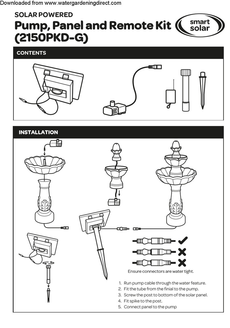
Smart Solar 2150PKD-G quick start guide

Generac Power Systems
Generac Power Systems VT-8 8mt owner's manual
