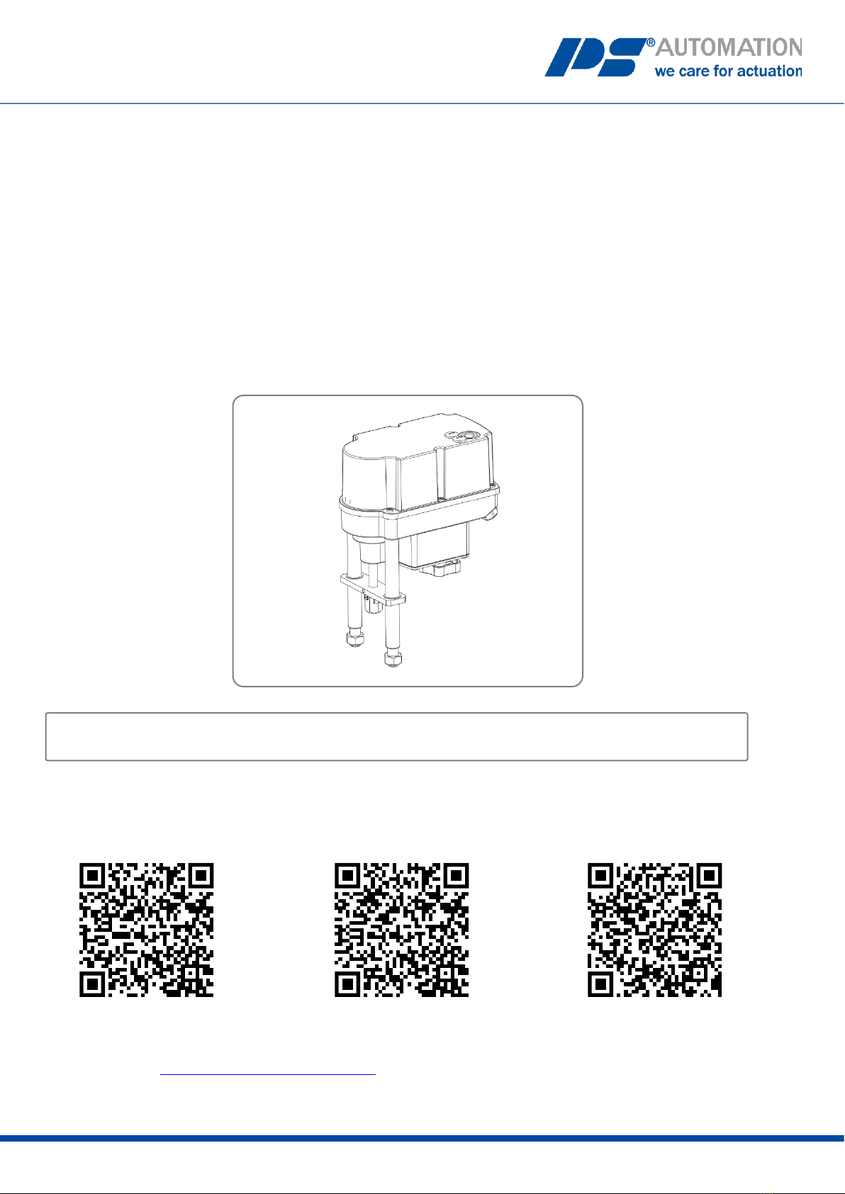
PS Automation PSF-EX User manual
The operating instructions in other languages can be found at the following QR codes:
Please note to scan the QR codes within an Ex-atmosphere only with a suitable end device!
Or follow the Link: www.ps-automation.com/downloads
Version 05/12/2022 Art. No.: 8035501 ©2022 PS Automation GmbH
Operating Instructions
PSF-M-EX approval according IECEx
(Certificate no.: IECEx TPS 22.0019X)
German
French
Italian
Subject to change!

2
Content
1. Product description.......................................................................................................................................................3
2. Applicable standards.....................................................................................................................................................3
3. Key figures.....................................................................................................................................................................4
3.1 Type code................................................................................................................................................................5
4. Symbols used and safety...............................................................................................................................................5
5. Intended use .................................................................................................................................................................6
5.1 Special conditions ...................................................................................................................................................7
6. Storage ..........................................................................................................................................................................7
7. Operating conditions and installation...........................................................................................................................7
8. Manual override and setting of the DIP switches.........................................................................................................9
8.1 Setting the actuators during commissioning (hood open) .....................................................................................9
8.2 Setting the actuators during operation (hood closed) .........................................................................................10
9. Valve mounting...........................................................................................................................................................10
9.1 Valve mounting for cut-off by force at extended actuator stem..........................................................................11
9.2 Valve mounting for cut-off by force at retracted actuator stem..........................................................................11
10. Opening and closing the hood ..................................................................................................................................11
11. Electric supply ...........................................................................................................................................................12
11.1 Safety instructions ..............................................................................................................................................12
11.2 Connection diagram............................................................................................................................................13
12. Display and functions................................................................................................................................................14
12.1 DIP switches ........................................................................................................................................................14
12.2 Operating buttons...............................................................................................................................................15
12.3 Status display ......................................................................................................................................................16
12.4 Automatic commissioning (see also chapter 12.2).............................................................................................16
12.5 Manual commissioning (see also chapter 12.2) .................................................................................................16
12.6 Manual operation (see also chapter 12.2)..........................................................................................................17
12.7 Handwheel..........................................................................................................................................................17
13. Operation..................................................................................................................................................................17
14. Commissioning..........................................................................................................................................................17
15. Maintenance and servicing.......................................................................................................................................18
15.1 Cleaning...............................................................................................................................................................18
15.2 Servicing..............................................................................................................................................................18
15.3 Spare parts ..........................................................................................................................................................18
15.4 Service address: ..................................................................................................................................................18
16. Decommissioning and disposal.................................................................................................................................18
17. Annex ........................................................................................................................................................................19
17.1 Accessories..........................................................................................................................................................19

3
1. Product description
The type PSF-**0*.*-*-Ex actuator is an industrial, multifunctional modulating actuator with fail-safe function for
the operation of industrial valves of various types across a wide range of applications. The actuator is designed
for assembly with valves and their motor operation.
It is used as an electric valve actuator in hazardous areas of
Ex zone 1, Ex d e, device protection level Gb or
Ex zone 21, device protection level Db installed in a fixed position using mounting columns.
An operating status (LED in Ex d motor assembly housing) can be displayed through an inspection glass in the
hood. The actuator can be operated by 2 push buttons in the cover (the micro switches for this are likewise
located in the Ex d housing).
Programming of the control (DIP switches) is possible in the safe range or in a voltage-free state. For this
purpose, the hood is detached and the fastening screws in the Ex d housing are removed.
To protect against environmental influences, the cover and lower section are powder-coated.
Conduit entries are available in the lower section of the housing for inserting the electrical cables.
The construction, as well as the interaction of the individual components and the housing regarding their
suitability for use in hazardous areas, are tested by PS Automation GmbH and confirmed by the identification
with the type label.
The type PSF-**0*.*-*-Ex actuator essentially consists of:
- the two mounting columns
- the drive shaft and
- the housing section
- the mechanical section (multi-stage spur gear) is located in the lower section of the housing (mounting plate)
- the Ex e/t terminal compartment is located in the upper section of the housing (underneath the cover hood),
this is formed by the hood and the upper side of the lower housing section (mounting plate)
- with conduit entries
- with connection panel for the electrical connections (electrical connection compartment)
- with Ed d motor control housing
2. Applicable standards
IEC 60079-0:2017/General requirements
IEC 60079-7:2015/Increased safety “e”
IEC 60079-31:2013/Protection by housing “t”
IEC 60079-1:2014/Flameproof enclosure “d”

4
3. Key figures
Certificate No.
IECEx TPS 22.0019X
Ex marking
Ex db eb IIC T6 Gb or
Ex db eb IIC T4 Gb or rather
Ex tb IIIC T80 °C Db or
Ex tb IIIC T100 °C Db
Size (electrical section)
approx. 240 x 135 x 181 mm (WxLxH)
(Ex e/Ex t housing)
Actuating power
Depending on variant
Operating time
0.5 - 1.0 mm/s
Stroke
40 mm-50 mm
Nominal voltage
24VAC/DC, 100-240VAC
Nominal current
maximum 1.8A AC / 1.1A DC
Backup fuse
(only for 100 - 240VAC power supply unit, installed in
power supply unit)
2AT 230VAC
External housing material
GD-AlSi9Cu3 (EX eb/tb housing)
Die cast
Surface treatment
Powder-coated, permissible total coating thickness ≤ 500µm
(incl. type label)
Ambient temperature range
extended
-10 °C ≤ Ta ≤ +40 °C
-10 °C ≤ Ta ≤ +60 °C
Temperature class
T6 (at Ta +40 °C) /T4 (at Ta +60 °C)
Max. surface temperature
80 °C (at Ta +40 °C) /
100 °C (at Ta +60 °C)
IP protection class
≥IP64

5
3.1 Type code
Example
PSF-M-402-EX
/
24VAC
/
50-60Hz
/
9W
/
5,0kN
/
1,0
Actuator type
Voltage supply
Frequency
Max. input power
Force
Stroking speed [mm/s]
4. Symbols used and safety
General dangers in case of non-observance of the safety instructions
The PSF-M-Ex actuators are built according to the latest state of the art and are operationally safe. Nevertheless,
hazards can arise from the actuators if they are not used by trained or at least instructed personnel and/or are used
improperly or for purposes other than those for which they are intended.
This threatens, for example
•Danger to life and limb of the user or third parties,
•Dangers to the user's property,
•Impairment of safety and function of the actuator.
It must be ensured that every person in charge of the installation, commissioning, operation, maintenance and
repair of the actuators has read and understood these operating instructions and this chapter in particular.
Safety-conscious work
•The actuators may only be operated by trained and authorised operating personnel.
•The safety instructions listed in this manual, the existing national regulations for accident prevention, as well as
any internal working, operating and safety instructions of the operator must be observed.
•The isolating procedures specified in the operating instructions must be observed for all work such as
installation, commissioning, set-up, operation, changes in operating conditions and operating methods as well
as maintenance, inspection and repair.
•Before working on potentially live areas, ensure that they are free of voltage.
•Observe IEC 60079-14 when installing the actuators.
•It must be ensured that the actuators are always operated in perfect condition. Externally visible damage and
defects, as well as changes in the operating behaviour which may affect safety, must be reported immediately.
6
Notice of hazards
The following hazard symbols are used in these instructions:
Attention! There are general hazards that can lead to property and/or
personal injury.
Caution! Life threatening electrical voltages may be present! There is a risk of material damage
and/or personal injury with danger to life.
Danger! This symbol warns of an imminent danger to the health of persons. Failure to follow
these notices may result in injury.
Attention! Observe handling instructions. Electrostatic sensitive components.
Further instructions
•During maintenance, inspection and repair directly after operation, increased surface temperatures on the
motor housing are to be expected. Danger of burns!
•Visible dust deposits must be removed immediately!
•The hood may only be opened in an explosion-free environment! When working in hazardous areas, the
European standards IEC 60079-14 “Erection of electrical installations in potentially explosive atmospheres” and
IEC 60079-17 “Testing and maintenance of electrical installations in potentially explosive atmospheres” must be
observed.
•When upgrading and operating the actuator with PS accessories, the operating instructions available for them
must be observed.
•Connections for the signal inputs and outputs are separated from the circuits that are dangerous to touch by
double insulation.
5. Intended use
•The type PSF-M-EX actuator is a fixed installed device for use in Ex zone 1, 2, 21 or 22. The type PSF-M-EX
actuator is not suitable for use in Zone 0 and Zone 20.
•The electrical data shown on the type plate as well as the device category for the place of use must be observed.
•The operator of an electrical system in a potentially explosive environment must keep the equipment in proper
condition, operate it properly, monitor it and carry out maintenance and repair work.
See also IEC 60079-17/IEC 60079-19.
•The PSF-M-EX actuators are constructed exclusively for use as electronic valve actuators. They are designed for
assembly with valves and their motorised operation.
•Any use other than this is considered unintended use. The manufacturer is not liable for damage resulting from
this.
•The actuators shall not be used outside the limit values cited in the data sheet, catalogue and/or order
documentation. Infringement negates all liability on the part of the manufacturer for any resultant damages.
•Proper intended use also includes compliance with the operating, maintenance and repair conditions from the
manufacturer.
•Mounting and adjustment of the actuator as well as its maintenance are not considered as intended use.
Enhanced safety precautions must be implemented in such situations!

7
•Assembly/disassembly, operating and maintenance work may only be carried out by suitable skilled personnel
familiar with the work. All generally applicable legal regulations and other binding guidelines for work safety,
accident prevention and environmental protection must be complied with.
•Unauthorised modifications to the actuators negate all liability on the part of the manufacturer for any resultant
damages.
5.1 Special conditions
•To avoid critical electrostatic charges,
•the devices must not be installed in the vicinity of highly charge-generating processes.
•the devices are only cleaned with damp or antistatic fabric.
•The length of the flameproof joints is partly larger and the distances of the flameproof joints is partly smaller than
the values of table 3 for IIC of IEC 60079-1:2014. Information regarding the dimensions of the flameproof joints
can be obtained from the manufacturer.
•The fastening screws of flameproof enclosure parts must have a yield strength of at least 640 N/mm².
6. Storage
The following points must be observed for proper storage:
•Store only in well-ventilated, dry rooms.
•Store on a rack, on wooden pallet or similar to protect from ground moisture.
•Cover to protect from dust and dirt.
•Protect actuators from mechanical damage.
7. Operating conditions and installation
•When setting up and operating explosion-protected electrical equipment, care must be taken to ensure
protection against harmful environmental influences that restrict the intended use of the equipment. These can
be, for example, protection against aggressive liquids or climatic influences. During installation, observe
IEC 60079-14 and other applicable national standards and regulations at the place of installation.
•The information on the type plate and the applicable documents must be taken into consideration.
For cable entries with special installation conditions, (see "X" marking on the cable entry), the relevant
instructions given by the manufacturer must be followed.
•The actuators can be operated in the IECEx version at ambient temperatures according to the data sheet.
•The duty cycles are according to IEC 60034-1, 8: S2 for short-time duty and S4 for modulating operation (for
actuator-specific values, see actuator-specific data sheets).
•For protection against humidity and dust, the actuators are designed according to EN 60529 with protection class
IP65.
8
Installation
•The conductor must be connected carefully at the terminal points so that the individual wires are not damaged.
The maximum connection data on the type plate and the applicable documents must be taken into consideration.
•The device must be integrated into a suitable earthing or equipotential bonding system before commissioning, a
connection part (4 mm²) is available for this purpose on the underside of the actuator. The effectiveness must be
checked before initial commissioning.
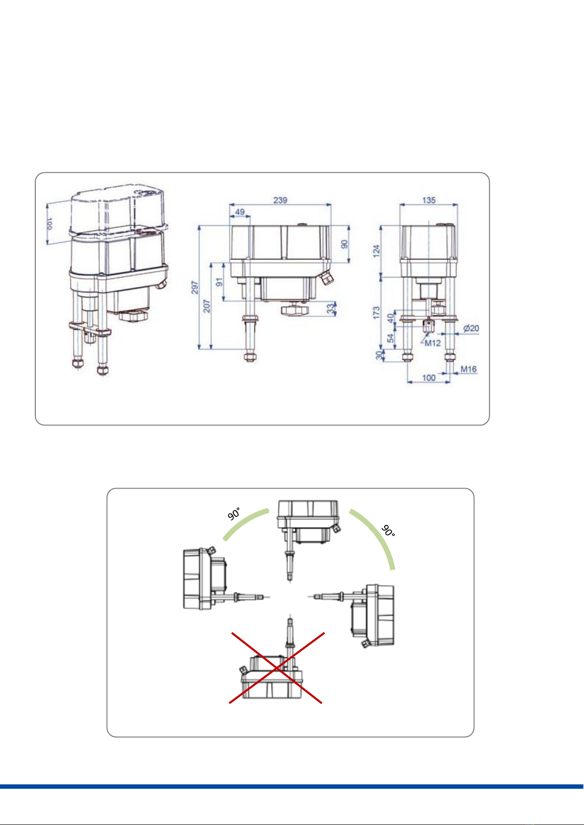
•The actuators must be installed with sufficient clearance to remove the hood (Figure 1).
•The mounting position is arbitrary with the exception of “hood downwards” (Figure 2).
Figure 1: Installation dimensions
Mounting positions
Figure 2: Mounting position

9
8. Manual override and setting of the DIP switches
8.1 Setting the actuators during commissioning (hood open)
When commissioning the actuators, the hood must be opened. The hood may only be opened in non-hazardous
areas and only in a dry environment (see chapter 10 for instructions).
To actuate the actuator during setting work (valve assembly and end position setting), an electrical manual override
by means of a push button is available (for operation, see chapter 12.2).
Programming of the control (DIP switch) is possible in voltage-free state (see chapter 12.1). To do this, first loosen 4
fastening screws of the upper cover of the Ex d control housing, then the upper cover can be removed from the Ex d
control housing. The upper cover of the Ex d control housing must not be damaged in the area of the joint gap when
removing it.
The top cover of the Ex d control housing must be installed considering the position of the push button and the light
guide (see figure 3). The tightening torque for the Ex d cover screws is 6 Nm, minimum quality of the screws 8.8.
(corrosion resistant).
The operating status (status display LED in the Ex d control housing) is indicated by a light guide in the Ex housing
(see chapter 12.3).
The electrical connection of the actuators is made via the terminal strip. The wiring diagram must be observed (see
chapter 11.2).
Figure 3: Manual override and setting of the DIP switches
Button B1
Light guide
Fastening
screws (4X)
Terminal strip
Button B2
DIP switch S1
DIP switch S2
Top cover detached
Position of buttons
and LEDs

10
8.2 Setting the actuators during operation (hood closed)
To actuate the actuator during setting work in potentially explosive atmospheres (end position setting), an electrical
manual override by means of a push button is provided in the hood (for conditions see chapter 12.2).
To reach the manual override, the screw plugs must be opened.
Figure 4: Manual override for setting work in potentially explosive atmospheres
9. Valve mounting
Figure 5: Valve mounting
Screw
plugs
Button B1
Button B2
Screw plugs removed
Pillar
Valve stem
Locking nut
Coupling
Pillar nut
Bracket
Spring-loaded clamp
with coupling pin
1 mm

11
9.1 Valve mounting for cut-off by force at extended actuator stem
Initial position: Valve stem is retracted, actuator stem is extended
1. Put actuator onto the bracket.
2. Remove the coupling pin and screw the coupling 13 mm on the valve stem. There must be a 1 mm gap between
the pillars and the bracket.
3. Insert the spring clamp with the coupling pin again and fix the locking nut.
4. Connect the actuator to electric supply.
5. Retract the actuator spindle manually until the edges of the pillars rest on the bracket.
6. Screw and tighten the pillar nuts.
9.2 Valve mounting for cut-off by force at retracted actuator stem
Initial position: Valve stem is extended, actuator stem is retracted
1. Put actuator onto the bracket, screw on the pillar nuts and tighten.
2. Remove the coupling pin and screw the coupling 13 mm on the valve stem. There must be a 1 mm gap between
the pillars and the bracket.
3. Connect the actuator either by means of a handwheel or electrically (see chapter 11.) and retract the actuator by
means of manual operation (see chapter 12.6) until the spring-loaded clamp with coupling pin can be re-inserted.
10. Opening and closing the hood
The hood may only be opened in non-hazardous areas and only in a dry environment.
Take appropriate ESD handling precautions before opening the housing:
•Earth the actuator.
•Touch earthed housing parts before opening the hood.
TRUE
FALSE
Before tightening the fastening nuts, the pillars must be
seated on the valve bracket. If necessary, correct the
position of the actuator via the manual override. In case of
non-compliance: Damage to the actuator!

12
11. Electric supply
11.1 Safety instructions
During the connection of the mains voltage, this must be disconnected and secured against
unintended reactivation.
The actuator hood must be opened for the electrical connection (see chapter 10).
The mains connection cables must be designed for the nominal current of the actuator.
Yellow-green coloured wiring shall be used only for connecting the protective earth connections.
The cable entry options (cable glands) on the actuator side are located on the lower part of the housing.
For this purpose
- 2x M20 x 1.5
- 1x M16 x 1.5
are available for feeding through the cables from the outside to the inside (see chapter 10).
When guiding the cables through the cable glands, take the maximum bending radius of the cables into account.
Unused entries must be closed by suitable blanking elements.
As the PSF-M-Ex electrical actuators do not have an internal electrical disconnect device available, a switch or circuit
breaker must be provided in the building installation. This must be located in the vicinity of the device, easily
accessible to the operator and must be identified as a disconnect device for the device.
Furthermore, the building installation must provide over-current protection devices according to IEC 60364-4-41 for
the connection of actuators of protection class I or protection class III at 24 VAC / 24 VDC.
All mains connection lines and control lines must be mechanically
secured ahead of the terminals with suitable measures to prevent
unintentional loosening.
Mains connection lines and control lines shall not be routed
together in one line but rather two separated lines shall be used in
all situations!
Opening:
First loosen all screws with a suitable screwdriver, then
unscrew them completely from the gearbox housing. The
screws are loss-proof. Remove the hood carefully so as not
to damage the seal.
Closing:
Place the cover on the gearbox housing and press lightly.
Lightly tighten all the screws, then tighten them crosswise.
It must be ensured that all screws are firmly tightened to
guarantee protection against ingress of water and dust in
accordance with EN 60529 to IP65. The tightening torque
for the Ex e/t hood is 3 Nm.
Figure 6: Opening and closing the hood
Hexagon socket
screw

13
11.2 Connection diagram
Figure 7 shows the electrical connection for standard drives. The wiring diagram in the actuator is binding for the
connection. For the connection of optional accessories, please refer to the respective operating instructions.
Figure 7: Electrical connection Figure 8: Connection for potential equalisation
The protective earth line is connected at the point marked PE on the actuator.
The connection for equipotential bonding is made at the external equipotential bonding connection
of the actuator.

14
12. Display and functions
12.1 DIP switches
S1
Function
1
2
3
4
5
6
7
8
Signal
Set value
Position feedback
Voltage
On
On
Off
Off
Off
On
Off
On
Current
Off
Off
On
On
On
Off
On
Off
S2
function
1
2
3 1)
4 1)
5
6
7
8
9 1)
10
Control via set value
On
Control via binary inputs
Off
Extend valve stem with increasing set value
On
Retract valve stem with increasing set value
Off
Automatic
commissioning
Closing with force / opening with force
On
On
Off
Closing with force / opening with stroke
On
On
On
Closing with force / opening with 20 mm
stroke
On
Off
x
Closing with force / opening with 30 mm
stroke
Off
On
x
Closing with force / opening with 40 mm
or 50 mm stroke (PSF-M405-EX)
Off
Off
x
Manual
commissio
ning
Closing with force / opening with
required stroke
On
On
On
Set value range / feedback signal: 0-10 V / 0-20 mA
On
On
On
Set value range / feedback signal: 2-10 V / 4-20 mA
Off
On
On
Set value/split range 5-10 V/10-20 mA
On
On
Off
Set value/split range 6-10 V/12-20 mA
Off
On
Off
Set value/split range 0-5 V/0-10 mA
On
Off
On
Set value/split range 2-6 V/4-12 mA
Off
Off
On
Cut-off by force with valve stem extended
On
Cut-off by force with valve stem retracted
Off
LINEAR valve curve set value/position
Off
QUICK OPENING valve curve set value/position
On
1) “Opening with force” refers exclusively to automatic commissioning. During operation, the actuator stops at the position
found. -> see chapter 13
2) When changing switches S2-3 and S2-4, a new calibration must be carried out so that this new operating mode becomes
effective!

15
12.2 Operating buttons
Function
Action
Button B1
Button B2
LED sequence
Manual
operation
Activate
Press for > 3 sec.
Press for > 3 sec.
Both LEDs flash
alternately
Retract valve stem
Press
Green LED flashes
Extend valve stem
Press
Red LED flashes
Stop
Both LEDs flash
alternately
Exit
Press for > 3 sec.
Press for > 3 sec.
Red or green LED
lights up
Automatic
commissioning
Start
Press for > 7 sec.
Both LEDs light up
Calibration ended
Green LED flashes 7x
(when calibration is
complete),
Green LED flashes
rapidly
(if calibration fails)
Exit
Press once
Red or green LED
lights up
Manual
commissioning
Activate
Press for > 7 sec.
Both LEDs flash
alternately
Retract valve stem
Press
Green LED flashes
Extend valve stem
Press
Red LED flashes
Start
Press for > 3 sec.
Press for > 3 sec.
Both LEDs light up
Exit
Press once
Red or green LED
lights up
Operating
speed
Set up1)
Press for > 4 sec.
Red LED flashes,
green LED lights up /
100% 3x
75% 2x
50% 1x
Change
Press once to
change a level
Red LED flashes,
green LED lights up /
100% 3x
75% 2x
50% 1x
Adopt
Press once
1) If no further action is taken, the actuator automatically exits this setting function after 15 sec. and does not change the
setting.

16
12.3 Status display
Green LED
Red LED
Actuator not calibrated
Off
Flashes rapidly
Normal operation / actuator moves
On
Off
Normal operation / actuator
stationary
Off
On
Manual mode active
Flashes alternately
Flashes alternately
Manual mode: Valve stem is
extended
Off
Flashes
Manual mode: Valve stem is
retracted
Flashes
Off
Automatic commissioning running
On
On
Automatic and manual
commissioning successful
Flashes 7 x - 1.5 sec. off
On
Automatic commissioning
failed
Flashes rapidly
On
Over-voltage
Flashes 1 x - 1.5 sec. off
On
Under-voltage
Flashes 2 x - 1.5 sec. off
On
Memory error
Flashes 3 x - 1.5 sec. off
On
Set value error (< 1 V, < 2 mA)
Flashes 4 x - 1.5 sec. off
On
Torque fault
Flashes 5 x - 1.5 sec. off
On
Under/over-temperature
Flashes 6 x - 1.5 sec. off
On
Blue LED: Ready-to-operate indicator lights up when the supply voltage is applied. LED illumination facilitates
reading of the DIP switch position.
12.4 Automatic commissioning (see also chapter 12.2)
•Check secure connection between valve and actuator.
•To start automatic commissioning, press button B2 for at least 7 seconds.
-Option 1: “Opening with force - Closing with force”: The actuator moves to the open-end position by force
and back again to the closed end position.
-Option 2: “Open with calibrated stroke” (20/30/40 mm) or (20/30/50 mm for PSF-M405-EX): The closed
end position is saved and the stroke is calculated based on the setting. If the possible travel path is less than
the preset stroke, the stroke for operation is automatically reduced to the resulting maximum possible
value.
•After successful commissioning, the green LED flashes seven times.
•Then press button B1 to return to normal operation.
•After successful commissioning, check the determined or adjusted stroke by setting the set value and the valve
position.
•Unsuccessful commissioning is signalled by the green LED flashing rapidly. Check valve installation.
•For commissioning, it is necessary that a residual stroke of at least 1 mm is available in "Closing direction with
force" before the actuator has reached its mechanical stop. Furthermore, the actuator must be able to perform
a stroke of at least 5 mm.
12.5 Manual commissioning (see also chapter 12.2)
•Check that the gland between the valve and the actuator is secure.
•To activate the individual calibration, press button B1 > at least 7 seconds.

17
•The actuator can be moved manually with buttons B1 and B2 until the desired open-end position of the valve is
reached.
•The calibration of the two end positions is started and saved by pressing B1 and B2 simultaneously for at least 3
seconds.
•After successful calibration, the green LED flashes seven times.
•Then press button B1 to return to normal operation.
•Check the adjusted stroke by setting the set value and measuring the actual value.
•Unsuccessful calibration is signalled by the green LED flashing rapidly.
•For commissioning, it is necessary that a residual stroke of at least 1 mm is available in "Closing direction with
force" before the actuator has reached its mechanical stop. Furthermore, the actuator must be able to perform
a stroke of at least 5 mm.
12.6 Manual operation (see also chapter 12.2)
•Press and hold buttons B1 and B2 simultaneously for at least 3 seconds to activate manual operation.
•Press button B1 to retract the valve stem.
•Press button B2 to extend the valve stem.
•Press and hold buttons B1 and B2 simultaneously for at least 3 seconds to exit manual operation.
12.7 Handwheel
•Press the handwheel towards the housing: the motor is deactivated.
•Keep the handwheel pressed and turn it:
oto the left: the valve spindle moves downwards.
oto the right: the valve spindle moves upwards.
•Release the handwheel: the handwheel is inoperative, after 5 seconds the motor is reactivated.
13. Operation
The operator of an electrical system in a potentially explosive environment must keep the equipment in proper
condition, operate it properly, monitor it and carry out maintenance and repair work.
See also IEC 60079-17/IEC 60079-19.
During operation, all internal parameters, such as the required motor torque and the current position, as well as the
operating states of the actuator are continuously monitored. This ensures that the actuator is positioned with
optimal accuracy and that the valve is always closed correctly.
End position operating behaviour
Depending on the setting of DIP switch S2.1, the end position switch-off takes place in operation in one end position
at the found/selected position, and in the other end position by force (see chapter 12.2).
14. Commissioning
•Before the equipment is initially commissioned, it must be checked for its suitability in the
relevant zone on the basis of its marking. The values specified on the type plate and in the
applicable documents must not be exceeded.
•Commissioning and use may only take place when the operating equipment is correctly
arranged within the system and is undamaged and clean.
•Opening the hood (see chapter 10), placing the actuator on the valve (see chapter 9),
making the electrical connection (see chapter 11).
•Carry out automatic (see chapter 12.4) or manual commissioning (see chapter 12.5).
•Close the hood (see chapter 10).
18
15. Maintenance and servicing
The actuators are maintenance-free under the operating conditions specified in the data sheet. The gearboxes are
lubricated for life and do not require relubrication.
Attention!
During maintenance and servicing, the actuator must not be operated electrically.
Personnel carrying out work and maintenance and servicing must be skilled and familiar with the work.
15.1 Cleaning
Use a damp cloth for cleaning.
Please do not use any cleaning agents containing solvents, as these can make the inscription on the safety stickers
and the type plate illegible. The actuator must not be moved during the cleaning process.
15.2 Servicing
The actuators are pre-tensioned by a return spring, the gearbox housing
must not be opened.
Defective actuators must be returned to our main factory in Bad Dürkheim, Germany, for repair
(see chapter 15.4).
15.3 Spare parts
Defective actuators can be returned to our main factory in Bad Dürkheim, Germany, to be investigated for damage
and its possible causes (see chapter 15.4).
15.4 Service address:
PS-Automation GmbH Tel.: +49 (0) 6322/ 94980-0
Phillip-Krämer-Ring 13 E-mail: info@ps-automation.com
D-67098 Bad Dürkheim www.ps-automation.de
16. Decommissioning and disposal
•Disconnect the mains connection and secure it against accidental reactivation.
•Open the hood.
•Remove external connections.
•Remove the actuator from the valve.
Disposal
The actuator is considered waste from electrical and electronic equipment and shall not be disposed of as household
waste.
The actuators are pre-tensioned by a return spring.
For disassembly, please contact our factory in Bad Dürkheim.

19
17. Annex
17.1 Accessories
Optional accessories are available for the actuators.
Technical data can be found in the corresponding data sheets.

20
Our subsidiaries:
For more subsidiaries and partners, please scan the following QR code or visit our website
at https://www.ps-automation.com/ps-automation/locations/?lang=en
PS Automation GmbH
Philipp-Krämer-Ring 13
D-67098 Bad Dürkheim
Tel.: +49 (0) 6322 949 80 –0
E-mail: info@ps-automation.com
www.ps-automation.com
India
PS Automation India Pvt. Ltd.
Srv. No. 25/1, Narhe Industrial Area,
A.P. Narhegaon, Tal. Haveli, Dist.
IND-411041 Pune
Tel.: <+ 91> 20 25 47 39 66
Fax: <+ 91> 20 25 47 39 66
E-mail: sales@ps-automation.in
Italy
PS Automazione S.r.l.
Via Pennella, 94
I-38057 Pergine Valsugana (TN)
Tel.: <+39> 04 61-53 43 67
Fax: <+39> 04 61-50 48 62
E-mail: info@ps-automazione.it
Other manuals for PSF-EX
1
This manual suits for next models
9
Table of contents
Other PS Automation Industrial Equipment manuals

Popular Industrial Equipment manuals by other brands


Baileigh
Baileigh Hare&Forbes MSS-14H Operator's manual

Parker
Parker SciLog FilterTec Plus Installation, operation & maintenance instructions

Netafim
Netafim NETAJET 4G user manual

Aventics
Aventics 580 PROFIBUS DP Technical manual

Lippert Components
Lippert Components SOLIDSTEP 2.0 Master Owner's Manual

TREND
TREND CRT/MK3 Original instructions


