Lippert Components SOLIDSTEP 2.0 User manual

Master Owner's Manual
Steps

User notice
The Table of Contents is an interactive field. Click on the desired
section to be taken immediately to the corresponding page.

TABLE OF CONTENTS
MANUAL STEPS 4
Introduction 4
Safety 4
Step Operation 5
Unfolding Steps 5
Folding Steps 5
Maintenance 5
Scratches 5
Lubrication 5
Anti-Skid Tape 5
SOLIDSTEP®2.0 6
Introduction 6
Safety Information 6
Operation 7
Release Steps 7
Storage of Steps 7
Adjust Leg Extension 7
SOLIDSTEP®3.0 9
System Information 9
Safety information 9
Operation 10
Release Steps 10
Storage of Steps 10
Adjust Leg Extension 10
VICTORY STEP™ 12
Introduction 12
Safety 12
Step Operation 13
Step Deployment 13
Height Adjustment 14
Step Removal 14
Handrail (if equipped) 15
Installation 15
Removal 16
Stowage 16
Storage of Victory Step (if installed) 16
Storage 16
Removal 17
Master Owner's Manual
The Master Owner's Manual is intended to provide information on Lippert Components Inc.'s most widely-
used products. Products described in the Master Owner's Manual may not be on every trailer. The trailer may
also have products not included in this manual. All manual information is subject to change without notice.
Revised editions will be available for free download at lci1.com/support. Manual information is considered
factual until made obsolete by a revised version. Manual information may be distributed as a complete
document only, unless Lippert Components provides explicit consent to distribute individual parts.

Rev: 11.08.19 Page 4 CCD-0001573-11
Moving parts can pinch, crush or cut. Keep clear and use caution.
The “WARNING” symbol above is a sign that an installation procedure has a safety risk involved and
may cause death or serious injury if not performed safely and within the parameters set forth in
this manual. The trailer MUST be supported per manufacturer's recommendations before working
underneath. Failure to do so may result in death, serious personal injury or severe product or
property damage.
Introduction
This document details the operation and maintenance of manual steps.
Safety
STEPS
MANUAL STEPS

Rev: 11.08.19 Page 5 CCD-0001573-11
Step Operation
Unfolding Steps
1. Pull out on the top lip of the step vertically stored (Fig. 1A).
2. Pull up and out on the back of step resting on the second step (Fig 2A).
3. Unfold bottom step (Fig. 3).
Folding Steps
1. Pull up on bottom step and fold over the second step (Fig. 2A).
1. Pull up on bottom of steps and fold inward under top step (Fig. 1A).
Maintenance
Scratches
1. Clear any chipped paint or material adhering to scratched area.
2. Apply automotive grade primer to scratch.
3. Paint primed area with automotive high gloss paint.
Lubrication
1. Remove all dirt and foreign matter from hinge areas.
2. Lubricate hinge areas in between the sheet metal portions of the steps.
NOTE: Utilize a dry silicone lubricant. Wet lubricants will attract dirt and possibly cause damage to the
hinge areas.
Anti-Skid Tape
1. Inspect steps for loose, missing or damaged anti-skid tape.
2. Replace anti-skid tape as necessary.
Fig. 1
A
A
Fig. 2 Fig. 3
Rev: 11.08.19 Page 6 CCD-0001573-11
Introduction
The SolidStep® 2.0 is a trailer entry step assembly mounted to the side of any trailer, providing an ease of
entry, regardless of level ground.
Safety Information
Failure to follow the instructions provided in this manual may result in death, serious personal
injury, product or property damage, or voiding of the component warranty.
No repairs should be attempted by anyone other than a qualied professional. The deployment
and retraction of the Step assembly can cause injury if proper precautions are not taken. The Step
assembly was designed for an operational weight rating of 400 lbs.
Moving parts can pinch, crush or cut. Keep clear and use caution.
Always wear eye protection when performing service or maintenance to the trailer. Other safety
equipment to consider would be hearing protection, gloves and possibly a full face shield,
depending on the nature of the service.
SOLIDSTEP®2.0
STEPS
Rev: 11.08.19 Page 7 CCD-0001573-11
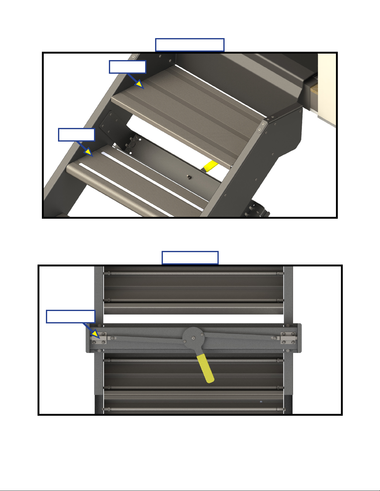
Operation
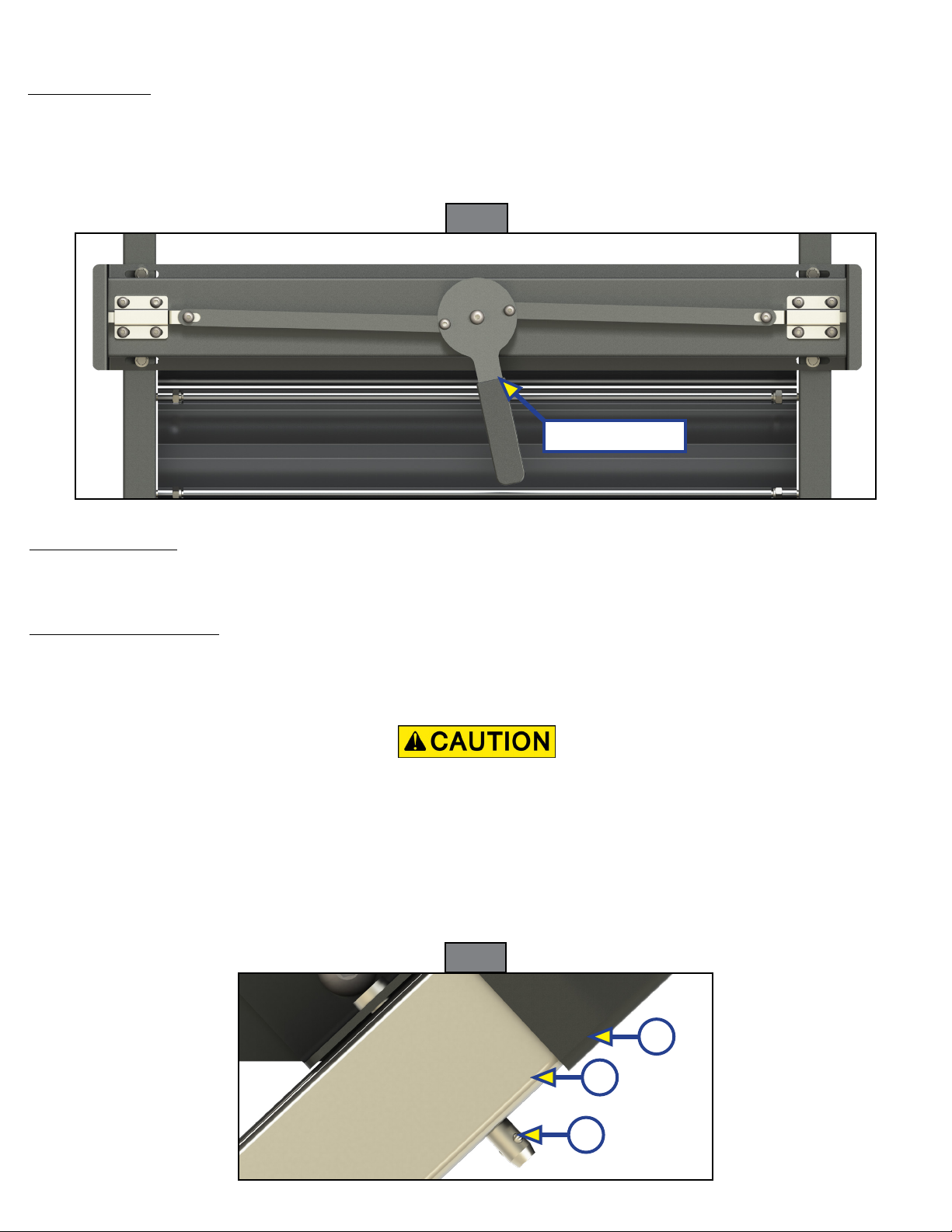
Release Steps
1. Disengage transport lock (Fig. 1).
2. Firmly grasp and pull out the vertically stored SolidStep and firmly rest it on the ground.
3. Adjust leg extensions as needed, see Leg Extension Adjustment section.
Fig. 1
Storage of Steps
1. Retract leg extensions, if desired.
2. Lift up SolidStep to its stored position and make sure the transport lock has been engaged.
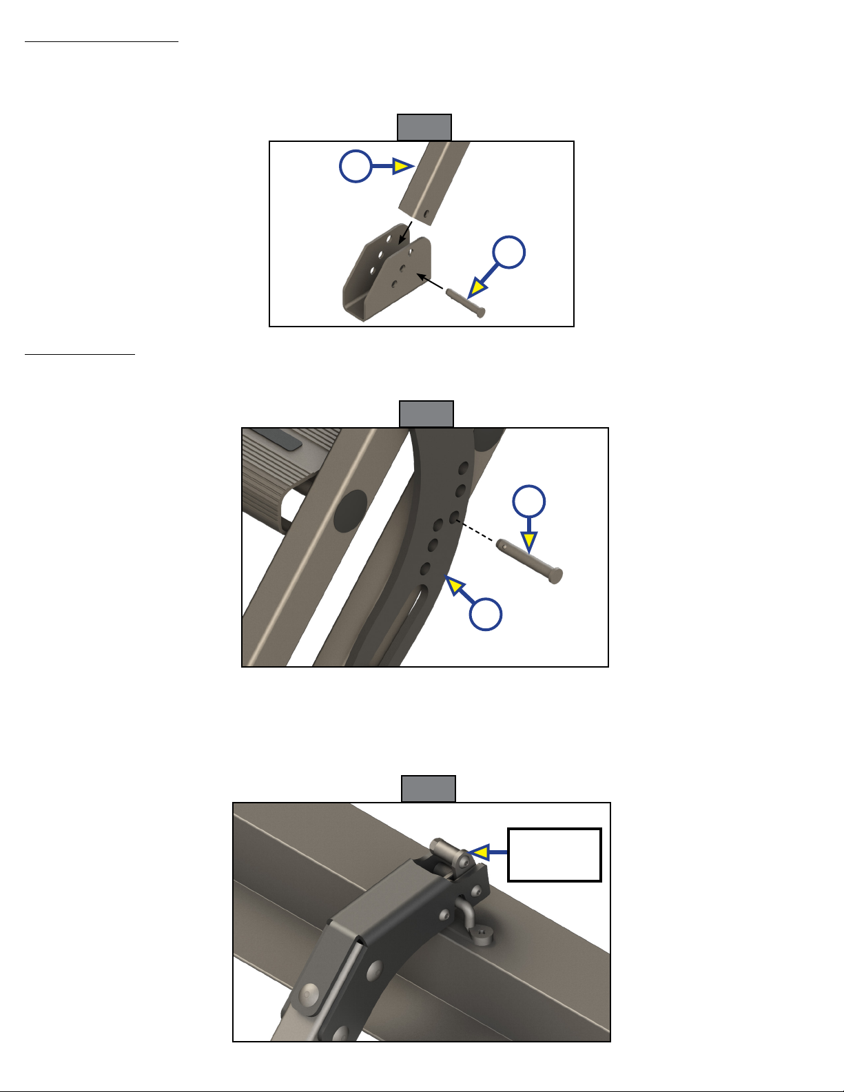
Adjust Leg Extension
The leg extension is secured with a quick release clevis pin. Adjustments can be made to the leg extensions
in 1" increments by moving the inner leg up or down for the optimal angle and to adjust for the ground
surface angle.
Transport Lock
Moving parts can pinch, crush or cut. Keep clear and use caution.
1. To extend the inner leg (Fig. 2B):
A. Remove the quick release clevis pin (Fig. 2A) from the tube and the slot in the angle.
B. Extend the inner leg to the ground and at an angle so the steps are parallel to the ground and are
level.
C. Replace the quick release clevis pin in the tube and slot and into the closest inner leg hole that
intersects with the outer leg's slot to where the inner leg and the outer leg (Fig. 2C) meet.
A
B
C
Fig. 2

Rev: 11.08.19 Page 8 CCD-0001573-11
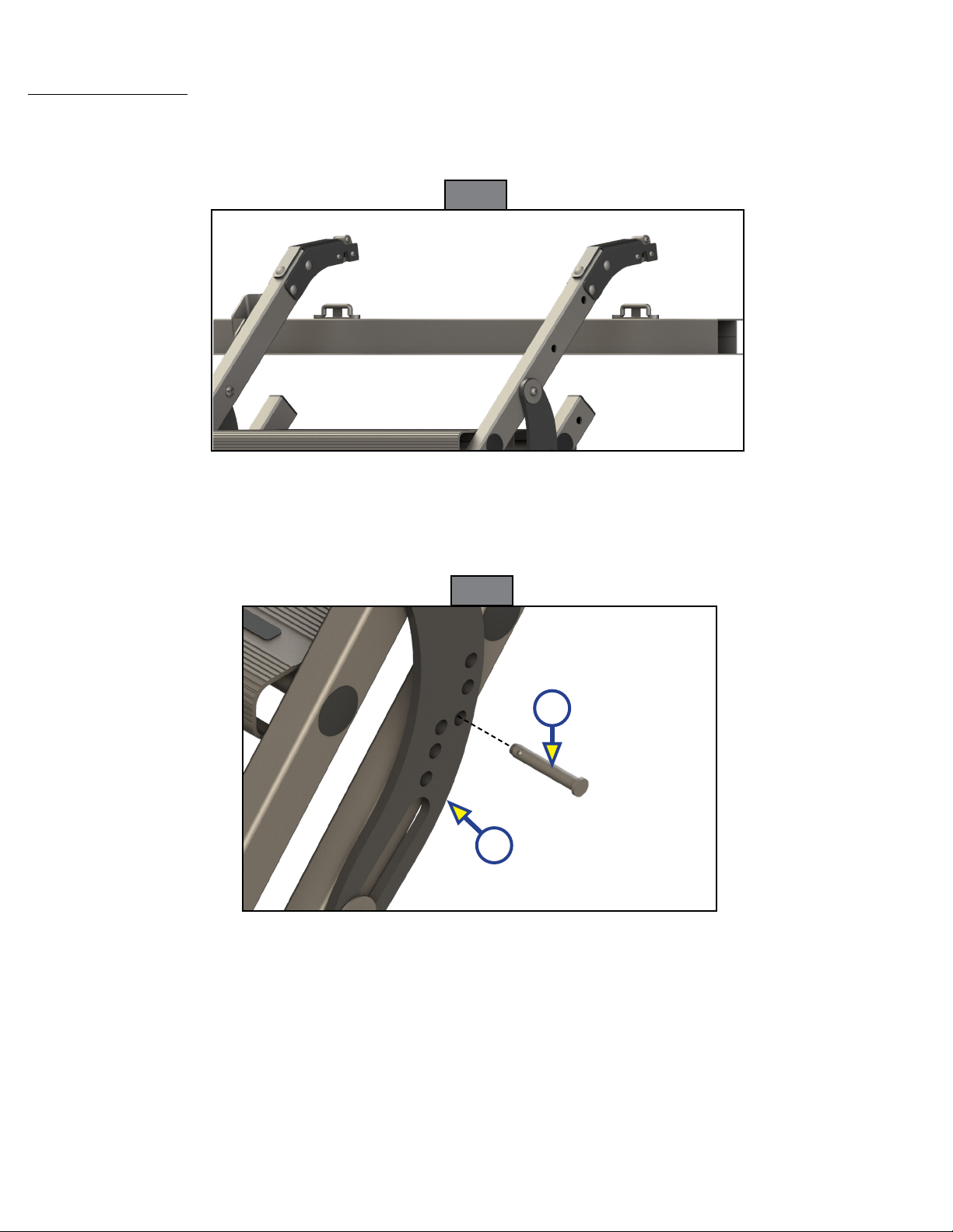
2. To retract the inner leg:
D. Remove the quick release clevis pin from the outer and inner legs.
E. Retract the inner leg.
F. Reinstall the quick release clevis pin into the outer leg slot and into the closest inner leg hole that
intersects with the outer leg's slot.
G. The step assembly is shown in the upright stored position, as viewed from underneath the step
assembly in figure 3.
Moving parts can pinch, crush or cut. Keep clear and use caution.
Transport Lock
Fig. 3
Rev: 11.08.19 Page 9 CCD-0001573-11
System Information
The SolidStep® 3.0 is a trailer entry step assembly mounted to the side of any trailer, providing an ease of
entry, regardless of level ground.
NOTE: Step identification tags are located under one of the step extrusions, typically the top full step.
Failure to follow the instructions provided in this manual may result in death, serious personal
injury, product or property damage or voiding of the component warranty.
Always wear eye protection when performing service or maintenance to the trailer. Other safety
equipment to consider would be hearing protection, gloves and possibly a full face shield,
depending on the nature of the service.
No repairs should be attempted by anyone other than a qualied professional. The deployment
and retraction of the step assembly can cause injury if proper precautions are not taken. The step
assembly was designed for an operational weight rating of 400 lbs.
Moving parts can pinch, crush or cut. Keep clear and use caution.
Safety information
SOLIDSTEP®3.0
STEPS
Rev: 11.08.19 Page 10 CCD-0001573-11
Operation
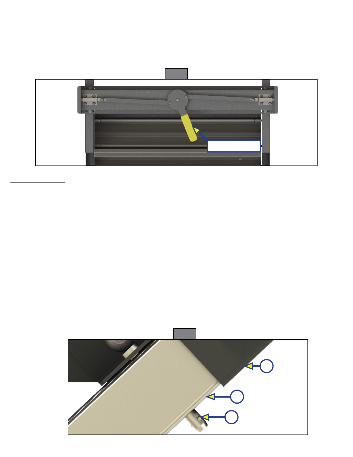
Release Steps
1. Disengage transport lock (Fig. 1).
2. Firmly grasp and pull out the vertically stored SolidStep and firmly rest it on the ground.
3. Adjust leg extensions as needed, see Leg Extension Adjustment section.
A
B
C
Storage of Steps
1. Retract leg extensions, if desired.
2. Lift up SolidStep to its stored position and make sure the transport lock has been engaged.
Adjust Leg Extension
The leg extension is secured with a quick release clevis pin. Adjustments can be made to the leg extensions
in 1" increments by extending or retracting the inner leg for the optimal angle and to adjust for the ground
surface angle.
1. To extend the inner leg (Fig. 2B):
A. Remove the quick release clevis pin (Fig. 2A) from the tube and the slot in the angle.
B. Extend the inner leg to the ground and at an angle so the steps are parallel to the ground and
level.
C. Reinsert the quick release clevis pin into the tube and slot closest to where the inner leg and tube
(Fig. 2C) meet.
2. To retract the inner leg:
A. Remove the quick release clevis pin from the tube and slot.
B. Retract the inner leg.
C. Reinsert the quick release clevis pin into the tube and slot.
Fig. 1
Transport Lock
Fig. 2
Rev: 11.08.19 Page 11 CCD-0001573-11
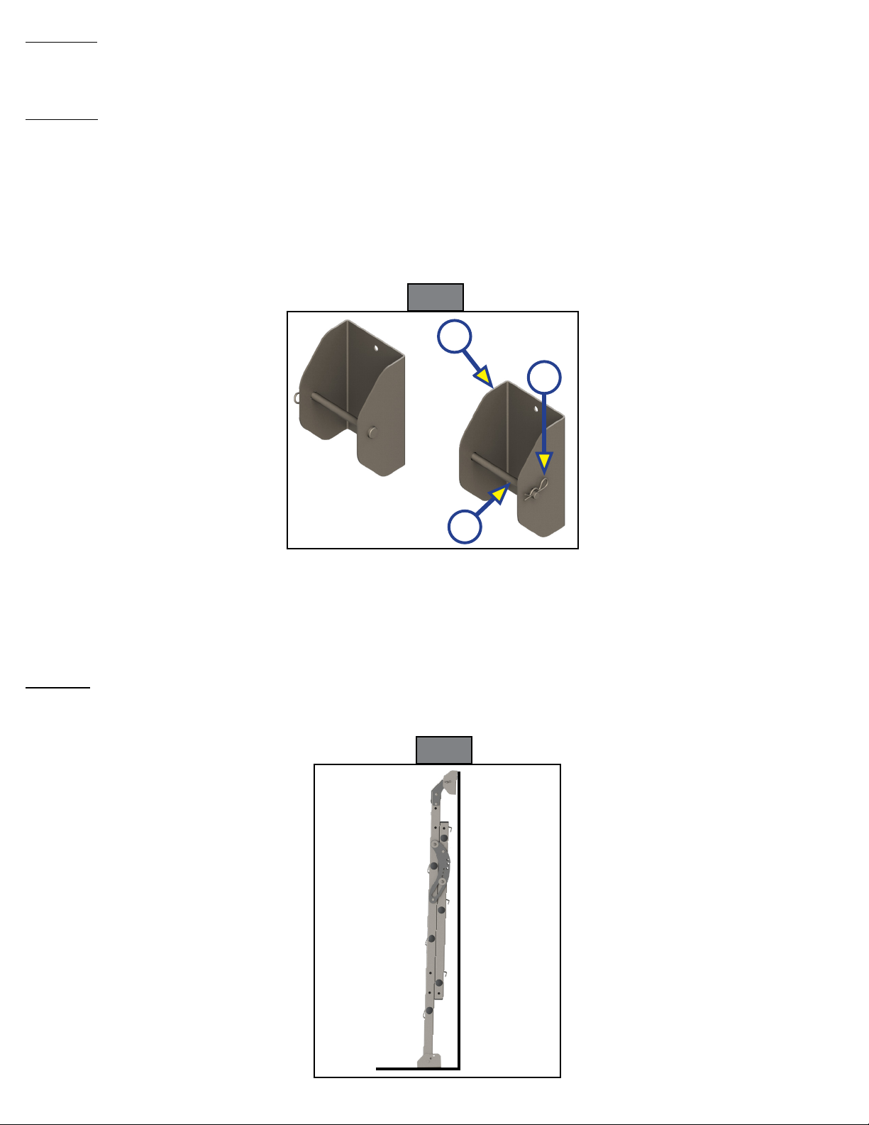
Top Step
Step Identification
Full Step
Plunger Bolt
Lock Assembly

Rev: 11.08.19 Page 12 CCD-0001573-11
Introduction
The Victory Step™ is an entry step assembly that can be mounted to the side of any patio opening to provide
ease of entry . The suggested deck height range should be between 23"-35" for a triple step and 30"-45" for a
quad step. The step assembly was designed for an operational weight rating of 300 pounds.
These instructions are for the following products:
The "WARNING" symbol above is a sign that a procedure has a safety risk involved and may cause
death or serious personal injury if not performed safely and within the parameters set forth in
this manual. Failure to follow the instructions provided in this manual may result in death, serious
injury, trailer damage or voiding of the product warranty.
Do not exceed specied weight limits. Exceeding weight limits may cause product damage and/or
personal injury.
Moving parts can pinch, crush or cut. Keep clear and use caution.
• 719691 - Triple Victory Step
• 726891 - Triple Victory Step with Handrail Kit
• 726894 - Quad Victory Step
• 726895 - Quad Victory Step with Handrail Kit
• 726866 - Handrail Kit
• 726890 - Garage Storage Kit
Safety
The "CAUTION" symbol above is a sign that a procedure has a safety risk involved that may cause
personal injury and/or product damage, including voiding of warranty, if not performed safely and
in accordance with the safety procedures stated herein.
VICTORY STEP™
STEPS
Rev: 11.08.19 Page 13 CCD-0001573-11
Step Operation
Step Deployment
1. Align the step latches at the top of the Victory Step with the installed footman loops (Fig. 1), then
lower until both step latches click into place around the footman loops.
2. Lower the Victory Step to the ground.
1. Remove and retain the ⁄" quick release lockpin (Fig. 2A) that extends through the bottom hole in the
adjustment plate (Fig. 2B) and both rails of the Victory Step. Repeat for the other side.
NOTE: After the quick release lockpins are both removed, the lower support tubes will drop down, causing
the angle of the step treads to change.
2. Grasp the back of any of the step treads and lift until the treads are all level with the ground. Continue
holding the steps level and replace one of the quick release lockpins into the nearest adjustment hole.
This will lock the step treads at the specified angle. Install the remaining quick release lockpin in the
identical hole in the other adjustment plate.
A
B
Fig. 1
Fig. 2
Rev: 11.08.19 Page 14 CCD-0001573-11
Height Adjustment
1. To adjust the foot height, lift the step and remove the fastening pin that secures the foot to the step tube.
2. Align the tube (Fig. 3A) to the desired holes then reinsert the fastening pin (Fig. 3B). Repeat on the other
side, if necessary.
A
B
Step Removal
1. Remove the quick release locking pin (Fig. 4A) from the adjustment plate (Fig. 4B). Repeat on other
side. Retain the pins for later use.
A
B
2. Collapse the Victory Step by pulling up on the back of the top step.
3. Insert the
quick release lockpin
through the bottom hole in the adjustment plate and both rails. Repeat on the
other side.
4. Release both of the step latches from the footman loops by pushing forward on the levers (Fig. 5).
5. Lift the Victory Step away evenly from the footman loops.
Step Latch
Lever
Fig. 3
Fig. 4
Fig. 5

Rev: 11.08.19 Page 15 CCD-0001573-11
A
B
B
Handrail (if equipped)
Installation
1. To remove the handrail (Fig. 6A) for installation, unscrew the fastening knobs (Fig. 6B). The knobs will
be used for installation of the handrail.
2. To install the handrail, align the short end of the handrail tube with the top bracket (Fig. 7A) on
the left side of the Victory Step and the long end of the handrail tube (Fig. 7B) with the bottom bracket (Fig. 7C).
3. Slide both ends of the handrail tube through the brackets and align with the holes in the back tube.
Screw the fastening knob (Fig. 7D) through the top hole in the handrail and into the back tube. Repeat
for the bottom hole. Hand tighten both knobs.
B
C
D
D
A
Fig. 6
Fig. 7
Rev: 11.08.19 Page 16 CCD-0001573-11
A
Removal
To remove the installed handrail from the Victory Step, unscrew the top and bottom fastening knobs (Fig. 7D)
then slide the handrail tube out of the brackets.
Stowage
To stow the handrail, align the holes in the handrail with the holes on the front face of the Victory Step
(Fig. 6). Screw the fastening knobs into the holes in the handrail, then hand-tighten until the handrail is
secured to the Victory Step.
Storage of Victory Step (if installed)
The Victory Step can also be stored using the accessory Garage Kit (sold separately), which includes brackets
(Fig. 8A), clevis pins (Fig. 8B) and hairpin cotter pins (Fig. 8C).
C
B
NOTE: The garage storage brackets are NOT designed to hang the Victory Step on the wall while
suspended above the floor. Suspending the Victory Step above the floor could lead to wall damage.
The garage storage brackets are designed to hold the Victory Step in a fixed position for travel
where the feet of the step are resting on the floor and the step is leaning slightly against the garage
storage brackets, which are attached to the wall.
Storage
1. Ensure that both feet on the Victory Step are set to the same height adjustment, then set the step so
both feet are on the ground about 3 to 4 inches away from the wall (Fig. 9).
Fig. 8
Fig. 9

Rev: 11.08.19 Page 17 CCD-0001573-11
A
2. Lean the top of the Victory Step towards the garage storage brackets then lower until both step
latches click into place around the clevis pins (Fig. 8B) on the garage storage brackets.
3. Make sure both step latches are secure around the clevis pins (Fig. 10) and both feet are on the floor.
Removal
To remove the Victory Step, push the step latches levers forward (Fig. 11A) then pull the step away evenly from
the clevis pins.
Fig.10
Fig. 11

Master Owner's Manual
The contents of this manual are proprietary and copyright protected by Lippert Components, Inc.
(“LCI”). LCI prohibits the copying or dissemination of portions of this manual unless prior written
consent from an authorized LCI representative has been provided. Any unauthorized use shall void any
applicable warranty. The information contained in this manual is subject to change without notice and
at the sole discretion of LCI. Revised editions are available for free download from lci1.com.
Please recycle all obsolete materials.
For all concerns or questions, please contact
Lippert Components, Inc.
This manual suits for next models
2
Table of contents
Other Lippert Components Industrial Equipment manuals

Lippert Components
Lippert Components Solera 728810 Installation instructions

Lippert Components
Lippert Components Happijac User manual

Lippert Components
Lippert Components Equa-Flex Triple Axle Installation instructions

Lippert Components
Lippert Components Power Gear 82-L0356 User manual

Lippert Components
Lippert Components Level Up LCD Travel Trailer User manual


 instruction manual")


