1. Sicherheit / Safety
Vorsicht! Lebensgefährliche elektrische Spannung kann anliegen! Sach- oder
Personenschäden sind durch geeignete Maßnahmen und Einhaltung der
Sicherheitsstandards zu vermeiden!
Caution! Dangerous electrical voltage can be present! Avoid personal or material
damages by observing applicable regulations and safety standards!
Die Standard-Schalter mit Silber-/ Nickel-Kontakten (2WE) sind geeignet für Schaltströme von 0,1 A bis
10 A (6 A induktiv) bei Spannungen im Bereich 24 V bis 230 V AC/DC. Bei kleinen Schaltströmen von 1 mA
bis 100 mA im Spannungsbereich von 5 V bis 30 V AC/DC empfehlen wir Schalter mit vergoldetem Kontakt
(2WE Gold). Der Kontaktwiderstand beträgt bei 2WE Gold 30 mΩ.
Standard switches with silver/nickel contacts (2WE) are suitable for currents from 0,1 A to 10 A (6 A
inductive) at voltages in the range of 24 V to 230 V AC/DC. For lower currents from 1mA to 100 mA at
voltages in the range of 5 V to 30 V AC/DC we recommend switches with gold contacts (2WE Gold). The
contact resistance with 2WE Gold is 30 mΩ.
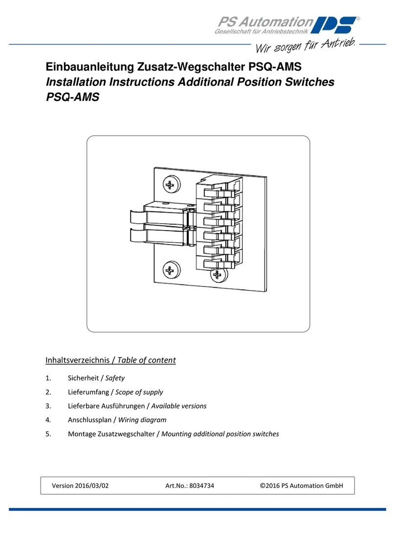
2. Lieferumfang / Scope of supply
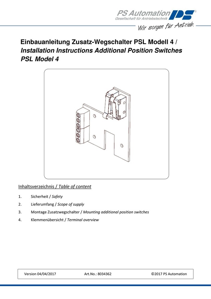
1x Zusatzwegschalterplatine /
1x Circuit board with position signal switches
1x Nockenträger mit zwei montierten Schaltnocken /
1x Cam plate with two mounted switching cams
Folgende Anschlussvarianten sind verfügbar:
3. Montage Zusatzwegschalter / Mounting position signal switches
Kupplung ganz ausfahren /
Drive coupling completely downwards
Sicherheitsregeln:
- Freischalten!
- Gegen Wiedereinschalten
sichern!
- Spannungsfreiheit feststellen!
- Benachbarte, unter Spannung
stehende Teile abdecken
oder abschranken!
Safety Regulations
- Disconnect mains!
- Prevent reconnection!
- Test for absence of
harmful voltages!
- Cover or close nearby
live parts!
❷
Nocke Kupplung eingefahren /
Cam coupling retracted
❶
Nocke Kupplung ausgefahren /
Cam coupling extended
1 2 3 4
A
B
C
D
4321
D
C
B
AError : Log oPS .b mp file no t foun d.
PSL PSR Übersicht 18-Jan-2012
1
1
PSL_Übersicht_Anschlussplan_C.Sch
Alle Rechte vorbehalten Allrights reserved
Projekt
Schaltplan Nr.
Bearbe itet
Geprüft
Freige geben
Index Änderung Name Datum Blatt
von
Name Datum
Gedrucktam
PS Automation GmbH
P hi ll i pp-K rä m er-Ri ng 13
67 090 B ad Dürkhe im
Vervielfältigung, Weitergabe an Dritte nur mit
schriftlicher Genehmigung
Filename
11:24:03
P.B ernh art 02 .04.04
M2
M1
=
F
3
1
2
4
6
5
X6
L
R
S
0
1
2
4
6
7
X5
Potentiometer 1
Potentiometer 1
Additional
Zusatzwegschalter
Additional
12V/24VDC
Zu / Close Auf / Open
Position Switch
14
15
16
X4
13
14
15
16
11
12
17
18
19
20
X5
L
R
S
Potentiometer 2
Potentiometer 2
Additional
1
2
3
X9
t
t
PE
L3
L1
L2
N
1
2
4
X5
PE
N
L2
L1
t
3-PhasenDrehstrom1-PhasenWechselstrom
1
2
X8
Heizung
Heating
t
3-Phasea.c.1-Phasea.c.
IndexC
Klemmenübersicht / Terminal overview
Öffner-Kontakt (Auslieferungszustand)/
Opening contact (condition at delivery):
Schließer-Kontakt / Closing contact:
