PS Engineering PMA8000BTi User manual
9800 Martel Road
Lenoir City, TN 37772
www.ps-engineering.com
P
PM
MA
A8
80
00
00
0B
BT
Ti
i
Document P/N 200-890-1722
Revision 1, March 2016
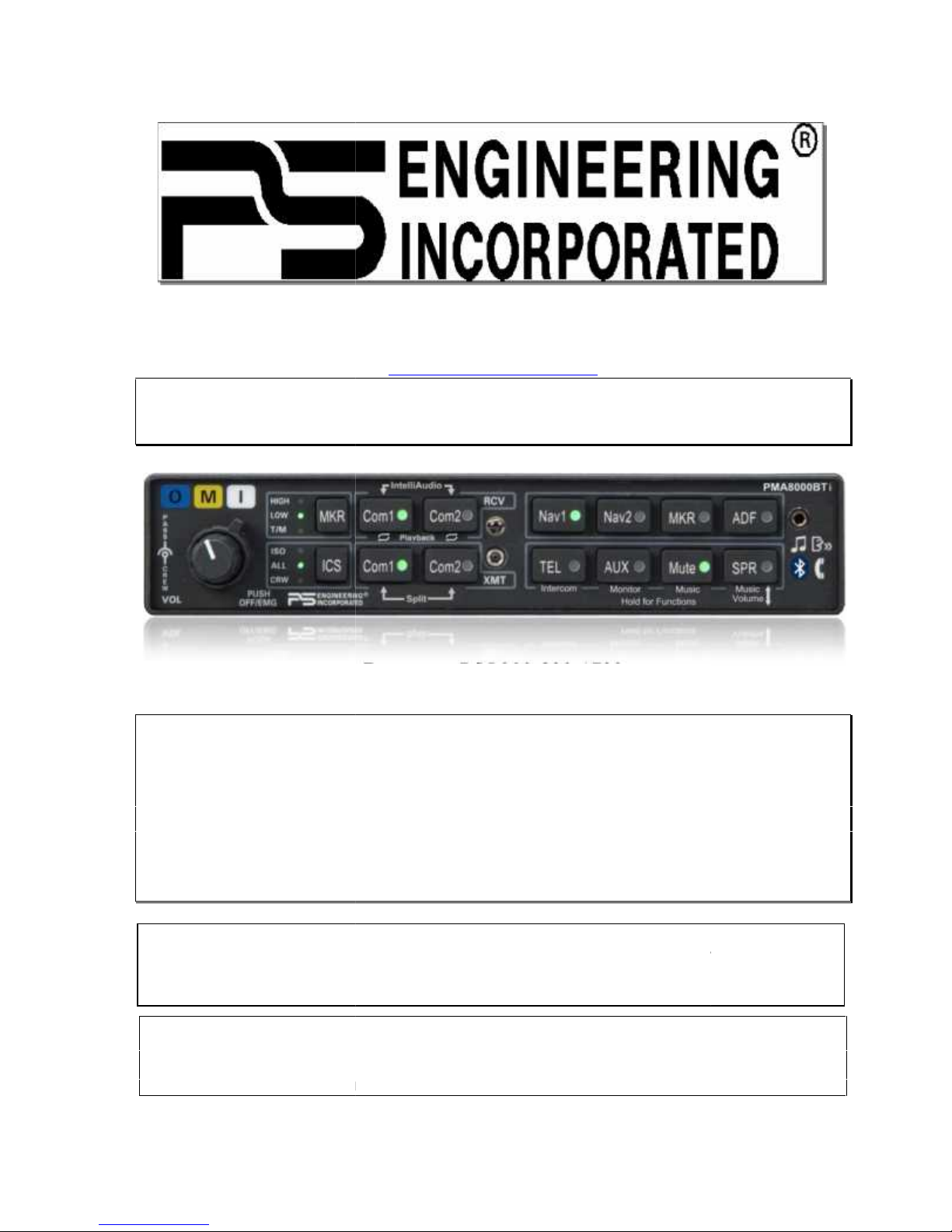
Audio Selector Panel with Marker Beacon Receiver
High-fidelity Stereo Intercom
System Installation and Operation Manual
FAA- TSO C50c, C35d
EASA ETSO C50c, 2C35d
Patented under one or more of the following;
No. 4,941,187; 5,903,227; 6,160,496 and 6,493,450
PS Engineering, Inc. 2016 ©
Copyright Notice
Any reproduction or retransmittal of this publication, or any portion thereof, without the expressed written permission of PS
Engineering, Inc. is strictly prohibited. For further information contact the Publications Manager at PS Engineering, Inc., 9800
Martel Road, Lenoir City, TN 37772. Phone (865) 988-9800, email contact@ps-engineering.com.
In certified aircraft, warranty is not valid unless this product is installed by an
Authorized PS Engineering dealer.
9800 Martel Road
Lenoir City, TN 37772
www.ps-engineering.com
P
PM
MA
A8
80
00
00
0B
BT
Ti
i
Document P/N 200-890-1722
Revision 1, March 2016
Audio Selector Panel with Marker Beacon Receiver
High-fidelity Stereo Intercom
System Installation and Operation Manual
FAA- TSO C50c, C35d
EASA ETSO C50c, 2C35d
Patented under one or more of the following;
No. 4,941,187; 5,903,227; 6,160,496 and 6,493,450
PS Engineering, Inc. 2016 ©
Copyright Notice
Any reproduction or retransmittal of this publication, or any portion thereof, without the expressed written permission of PS
Engineering, Inc. is strictly prohibited. For further information contact the Publications Manager at PS Engineering, Inc., 9800
Martel Road, Lenoir City, TN 37772. Phone (865) 988-9800, email contact@ps-engineering.com.
In certified aircraft, warranty is not valid unless this product is installed by an
Authorized PS Engineering dealer.

Table of Contents
Section I – GENERAL INFORMATION ................................................................ 1-1
1.1 INTRODUCTION............................................................................................................................ 1-1
1.2 SCOPE .............................................................................................................................................. 1-1
1.3 EQUIPMENT DESCRIPTION....................................................................................................... 1-1
1.4 APPROVAL BASIS ......................................................................................................................... 1-2
1.5 SPECIFICATIONS.......................................................................................................................... 1-2
1.6 EQUIPMENT SUPPLIED............................................................................................................... 1-4
1.7 EQUIPMENT REQUIRED BUT NOT SUPPLIED ...................................................................... 1-4
1.8 OPTIONAL ITEMS......................................................................................................................... 1-4
1.9 LICENSE REQUIREMENTS......................................................................................................... 1-4
Section II - INSTALLATION 2-1
2.1 GENERAL INFORMATION.......................................................................................................... 2-1
2.1.1 SCOPE.............................................................................................................................. 2-1
2.1.2 CERTIFICATION REQUIREMENTS ...................................................................................... 2-1
2.2 UNPACKING AND PRELIMINARY INSPECTION .................................................................................. 2-1
2.3 EQUIPMENT INSTALLATION PROCEDURES....................................................................................... 2-1
2.3.1 COOLING REQUIREMENTS ................................................................................................ 2-1
2.3.2 MOUNTING REQUIREMENTS ............................................................................................. 2-1
2.3.3 AUDIO PANEL MOUNTING RACK INSTALLATION ............................................................. 2-1
2.3.4 AUDIO PANEL TRAY AND CONNECTOR ASSEMBLY ......................................................... 2-2
2.4 CABLE HARNESS WIRING ................................................................................................................. 2-2
2.4.1 ELECTRICAL NOISE........................................................................................................... 2-2
2.4.2 EXISTING GMA340 INSTALLATION.................................................................................. 2-3
2.4.3 HEADPHONE WIRING........................................................................................................ 2-3
2.4.4 POWER .............................................................................................................................. 2-3
2.4.5 COMMUNICATIONS PUSH-TO-TALK.................................................................................. 2-3
2.4.6 AUDIO PANEL INTERFACE ................................................................................................ 2-3
2.4.7 TRANSMIT INTERLOCK ..................................................................................................... 2-4
2.4.8 BACKLIGHTING ................................................................................................................. 2-4
2.4.9 UNSWITCHED INPUTS........................................................................................................ 2-4
2.4.10 "SWAP" MODE ................................................................................................................ 2-5
2.4.11 TEL (DUPLEX) FUNCTION FOR CELL PHONES................................................................ 2-5
2.4.12 PUBLIC ADDRESS MODE................................................................................................. 2-6
2.4.13 PA MUTE (J2, PIN 12)..................................................................................................... 2-8
2.4.14 MISCELLANEOUS LOGIC OUTPUT (J2, PIN 18) ............................................................... 2-8
2.4.15 AUDIO ACTIVE OUTPUT ................................................................................................. 2-8
2.5 INTERCOM WIRING............................................................................................................................ 2-8
2.5.1 ENTERTAINMENT INPUTS.................................................................................................. 2-8
2.5.2 ENTERTAINMENT MUTING ................................................................................................ 2-8
2.5.3 CONFIGURING MUSIC INPUT WITH FUNCTION KEYS........................................................ 2-9
2.5.4 PLAYBACK BUTTON INSTALLATION ................................................................................. 2-9
2.6 MARKER BEACON INSTALLATION .................................................................................................... 2-9
2.6.1 MARKER ANTENNA INSTALLATION ................................................................................. 2-9
2.6.2 EXTERNAL MARKER LIGHTS ............................................................................................ 2-9
2.6.3 MIDDLE MARKER SENSE .................................................................................................. 2-9
2.7 ADJUSTMENTS ................................................................................................................................. 2-10
2.8 COMMUNICATIONS ANTENNA INSTALLATION NOTES ................................................................... 2-10
2.9 PMA8000BTIPIN ASSIGNMENTS ................................................................................................... 2-11
2.10 WIRING CHECKOUT ...................................................................................................................... 2-12
2.11 UNIT INSTALLATION...................................................................................................................... 2-12
2.12 OPERATIONAL CHECKOUT ........................................................................................................... 2-12

PS Engineering
PMA8000BTi IntelliAudio Audio Selector Panel and Intercom System
Installation and Operator’s Manual
200-890-1722 Page ii Rev. 1, March 2016
2.12.1 REQUIRED TEST EQUIPMENT ........................................................................................ 2-12
2.12.2 AUDIO PANEL TEST ...................................................................................................... 2-12
2.12.3 MARKER CHECKOUT .................................................................................................... 2-13
2.12.4 TEL CHECKOUT............................................................................................................ 2-13
2.12.5 INTERNAL RECORDER CHECKOUT................................................................................ 2-13
2.12.6 FUNCTION BUTTON CHECKOUT ................................................................................... 2-13
2.13 FINAL INSPECTION ........................................................................................................................ 2-13
Section III OPERATION 3-1
3.1 SCOPE .............................................................................................................................................. 3-1
3.2 COMMUNICATIONS TRANSMIT (XMT) SELECTION (2).................................................................... 3-1
3.3 AUDIO SELECTOR (4) ........................................................................................................................ 3-2
3.4 TELEPHONE (TEL) (9) ...................................................................................................................... 3-3
3.4.1 CELL PHONE SIDETONE .................................................................................................... 3-3
3.5 SPEAKER AMPLIFIER (5) ................................................................................................................... 3-3
3.6 MARKER BEACON OPERATION (10) ................................................................................................. 3-3
3.7 INTERCOM OPERATION..................................................................................................................... 3-4
3.7.1 INTELLIVOX® VOX-SQUELCH .......................................................................................... 3-4
3.7.2 INTERCOM VOLUME CONTROL (7) ................................................................................... 3-4
3.7.3 INTERCOM MODES (8) ...................................................................................................... 3-5
3.8 MUSIC AND MUSIC MUTING (6)........................................................................................................ 3-5
3.8.1 MUSIC IN PILOT ISO MODE............................................................................................... 3-6
3.9 TELEPHONE MODE (9) ...................................................................................................................... 3-6
3.9.1 CELLULAR TELEPHONE SIDETONE .................................................................................... 3-7
3.10 UTILITY JACK.................................................................................................................................. 3-7
3.10.1 CELLULAR PHONE........................................................................................................... 3-7
3.10.2 AUDIO ADVISORY INPUT ................................................................................................ 3-7
3.10.3 MUSIC INPUT .................................................................................................................. 3-8
3.11 SMART FUNCTION KEYS (SFK) ...................................................................................................... 3-8
3.11.1 “INTERCOM”ALTERNATE INTERCOM FUNCTION (A) ....................................................... 3-9
3.11.2 MONITOR (B).................................................................................................................. 3-9
3.11.3 MUSIC 1 VOLUME ......................................................................................................... 3-10
3.11.4 POWER ON ANNOUNCEMENT ........................................................................................ 3-10
3.12 BLUETOOTH®INTERFACE ............................................................................................................ 3-11
3.12.1 PAIRING AND UNPAIRING BLUETOOTH DEVICES .......................................................... 3-11
3.13 INTERNAL RECORDER AND PLAYBACK......................................................................................... 3-11
Section IV – Warranty and Service 4-1
4.1 WARRANTY........................................................................................................................................ 4-1
4.2 FACTORY SERVICE ............................................................................................................................ 4-1
Appendix A – External PTT Hook Up .................................................................... A
Appendix B – PMA8000 Installation Drawings .........................................................B
Appendix C – J1 Connector Interconnect ..................................................................C
Appendix D – J2 Connector Interconnect ..................................................................D
Appendix E – Instructions for FAA Form 337 and continuing airworthiness........E
9.1 INSTRUCTIONS FOR FAA FORM 337, AUDIO PANELS .........................................................................E
9.2 INSTRUCTIONS FOR CONTINUING AIRWORTHINESS, AUDIO SYSTEM ................................................E
Appendix F – RTCA DO160D Environmental Qualification Form ........................ F
Rev
Date
Change
0
JAN 2016
New Release of manual p/n 050-890-1722, for PMA8000BTi
1
March 2016
Added Remote ICS control input (S/N BTi1083 and above)

PS Engineering
PMA8000BTi IntelliAudio Audio Selector Panel and Intercom System
Installation and Operator’s Manual
200-890-1722 Page 1-1 Rev. 1, March 2016
Section I – GENERAL INFORMATION
1.1 INTRODUCTION
The PMA8000BTi represents another evolutionary step in cockpit audio control and intercommunications
utility. Using our patented IntelliVox® design, front panel utility jack, and pilot programmable configura-
tions, this marks the next level of audio control. The unit is designed for outstanding ergonomics and vis u-
ally defined mode annunciation and selection.
Before installing and/or using this product, please read this manual completely. This will ensure that you
will take full advantage of all the advanced features in the PMA8000BTi.
1.2 SCOPE
This manual provides detailed installation and operation instructions for the PS Engineering PMA8000BTi-
series of Audio Selector Panel/Intercom Systems. This includes the following units:
Model
Description
Part Number
PMA8000BTi
Stereo Audio Selector Panel with Marker Beacon, includes
utility jack and Internal Recorder System and Bluetooth
Connectivity
050-890-0712
1.3 EQUIPMENT DESCRIPTION
The PMA8000BTi is a state-of-the-art audio isolation amplifier and audio selector that contains an auto-
matic voice activated (VOX) intercom system and integral marker beacon receiver. It can switch two trans-
ceivers (Com 1, Com 2) and six receivers (Nav 1, Nav 2, ADF, DME, MKR and AUX).
A full duplex TEL mode allows the PMA8000BTi to act as an audio interface between aircraft headphone
and microphones and specific aircraft approved (FAA/FCC) cellular telephone equipment, through the
front mounted jack.
Warning: Use of non-aviation approved cellular telephone equipment may be prohibited by FCC regulation.
PS Engineering is not responsible for unauthorized airborne use of cellular telephones.
For airborne use, the PMA8000BTi must be interfaced with an approved system.
There are five unswitched inputs, available for traffic or EGPWS, autopilot disconnect, and/or radar altim e-
ter warning, with the fifth unswitched input through a front-mounted utility jack, when configured to act as
a fifth unswitched input.
Pushbuttons select the receiver audio source provided to the headphones. A SPR button allows the user to
listen to the receiver(s) selected on the cabin speaker. Except for the unswitched inputs, all speaker audio is
muted during transmit. Unswitched inputs 1, 3, and 4 are always presented to the aircraft speaker.
Unswitched input 2 will be presented to the speaker when the front panel SPR push button has bee n select-
ed.
Pushbutton switches select one of the communication transceivers for the pilot and copilot position, and
allows radio transmission. In "Split Mode" the PMA8000BTi has the ability to allow the pilot to transmit
on Com 1 while the copilot can transmit on Com 2. A fail-safe mode connects the pilot headphone and mi-
crophone to COM 1 if power is removed for any reason, or if the power switch is placed in the Off (Fail -
safe) position. Unswitched input #1 is also provided to the pilot headphone in fail -safe
A six-station voice activated (VOX) intercom is included in the PMA8000BTi. This system has PS Engi-
neering’s patented IntelliVox® circuitry that eliminates manual adjustments. The intercom system incorpo-
rates pilot isolate, all and crew modes, two independent stereo music inputs with "SoftMute™". Intercom
volume control is through two concentric front panel knobs and a pushbutton intercom mode switch. The
small volume knob controls the intercom level for the pilot and copilot, while the large knob con trols the
passenger intercom volume. Intercom squelch is automatic.

PS Engineering
PMA8000BTi IntelliAudio Audio Selector Panel and Intercom System
Installation and Operator’s Manual
200-890-1722 Page 1-2 Rev. 1, March 2016
A 3-light, 75 MHz Marker Beacon receiver is integrated in the PMA8000BTi. This provides the necessary
Marker Beacon lights and audio indications necessary for that portion of an Instrument Landing System
(ILS) approach. A pushbutton labeled MKR allows the pilot select high or low sensitivity as well as test
and mute modes.
In the PMA8000BTi, a Bluetooth® wireless interface is available for wireless telephone and music connec-
tion.
1.4 APPROVAL BASIS
FAA TSO Approval.
The PMA8000BTi-series Audio Selector Panels are FAA approved under TSO C50c (Audio Amplifiers)
and TSO C35d (Marker Beacon Receivers), ETSO C50c/ and 2C53d.
All systems comply with relevant portions of EUROCAE RTCA MPS WG No. 7/70 , DO-143 and (Marker
Beacon Receivers), ED-14C/DO-160C (Environmental Conditions and Test Procedures for Airborne
Equipment), ED12B/DO-178B, Level D (Software Considerations for Airborne Equipment) and ED-
18/DO-214 (Audio Systems Characteristics and Minimum Operational Performance Standards for Aircraft
Audio Systems).
Operation is subject to the following conditions:
This device may not cause harmful interference.
This device must accept any interference received, including interference that may cause un desired opera-
tion.
1.5 SPECIFICATIONS
TSO COMPLIANCE
Marker Beacon:
FAA TSO C35d, Class A ETSO 2C35d
Audio Selector/Intercom:
FAA TSO C50c, Class 1a ETSO C50c
APPLICABLE DOCUMENTS:
RTCA/DO-214 RTCA/DO-143 RTCA/DO-160D
Depth behind panel 7.15 in. (18.16 cm)
WEIGHT
PMA8000BT Unit
Rack with connectors
1.34 lb. (0.61 kg)
0.51 lb. (0.24 kg)
POWER REQUIREMENTS (Including Internal Lighting):
Voltage:
11 to 33 VDC
Maximum Current:
2.5 Amp (Externally protected by a 5A pull-type break-
er)
RTCA/DO-178B DO-254
ENVIRONMENTAL Qualifications:A1D1CABSMXXXXXXZBABATBXXE2XXX
Operating Temperature Range: -15º C to 55ºC
Altitude:Up to 50,000 feet in an non-pressurized area
DIMENSIONS: Height: 1.3 in. (3.3 cm) Width: 6.25 in. (15.9 cm)

PS Engineering
PMA8000BTi IntelliAudio Audio Selector Panel and Intercom System
Installation and Operator’s Manual
200-890-1722 Page 1-3 Rev. 1, March 2016
Audio Selector Specifications
Audio selector panel input impedance:
510
Input Isolation:
-60 dB (min.)
Speaker Muting:
-60 dB (min.)
Speaker Output (into 4 ) with no clipping
14 VDC:
28 VDC:
3 Watts (min.)
10 Watts (min.)
Receiver Inputs:
9 (Com 1, Com 2, TEL, Nav 1, Nav 2, ADF, DME,
MKR, AUX)
Unswitched Inputs:
5 (including front jack)
Transmitter Selections:
4 (Com 1, Com 2, TEL
Com1/2)
Speaker Impedance:
4
Headphone Impedance:
150 – 1000
Headphone Output:
38 mW each headset, no clipping <1% THD typical
Microphone Impedance:
150 - 600
Bluetooth Radio
Class 3, FCC ID QOQWT32AE
Intercom Specifications
Intercom Positions:
6 places (with individual IntelliVox® circuits)
Music Inputs:
2, (Independent, Stereo)
Music Muting:
>-30 dB "Soft Mute" when Com or intercom active.
Distortion:
<1% THD @ 38 mW into 150
Mic Freq. Response, 3 dB:
300 Hz - 6000 Hz
Music Freq. Response, 3 dB:
10 Hz – 26 kHz
MARKER BEACON RECEIVER:
Frequency:
75 MHz Crystal Controlled
Sensitivity:
Low:
High:
Capable of: (preset at factory for field application)
1000 Volts (Hard) (360 to 570 V soft)
200 Volts (Hard) (130 to 200 V soft)
Selectivity:
-6 dB at ±10 kHz
-40 dB at ±120 kHz
External Lamp Output:
7.5 (±4 VDC unloaded, at maximum brightness) VDC
positive when active, max. current 125 mA
MM Sense:
Active high (4.5 ± 1.0VDC)

PS Engineering
PMA8000BTi IntelliAudio Audio Selector Panel and Intercom System
Installation and Operator’s Manual
200-890-1722 Page 1-4 Rev. 1, March 2016
1.6 EQUIPMENT SUPPLIED
1 ea. of the following units:
Model
Description
Part Number
PMA8000BTi
PMA8000BT Audio Panel with IntelliAudio, Marker, Stereo
Intercom, and Bluetooth connectivity
050-890-0712
PMA8000BT Installation Kit: 250-890-0000
Description
Quantity
Part
Number
Installation rack assembly
1
430-890-0040
Rack back plate
1
430-890-0050
44-pin connector kit
2
120-891-2045-
Backshell, connector
2
625-025-2465
Backshell Retainer
2
431-881-0100
4 40 X 7/16 screw w/nylon patch
4
475-440-0007
4 40 X 3/8 screw w/nylon patch
4
475-440-1038
4-40 x ¼” screw with lock washer
2
475-440-0001
Solder Lug
2
475-009-0001
Cable Clamp
1
625-001-0002
#6-32 x ½” Flat head Philips screw
6
475-632-0012
#6-32 Clip Nut
6
475-630-0002
1.7 EQUIPMENT REQUIRED BUT NOT SUPPLIED
a. Circuit Breaker: 1 ea; 5 amp PULL TYPE REQUIRED for PMA8000BT
b. Speaker, 4
c. Headphone Jacks (Stereo, as Required)
d. Microphone Jacks (as Required)
e. Headphones, 150 (Stereo), up to 6 as required
f. Microphones, up to 6 as required
g. Marker Antenna (75 MHz, VSWR <1:1.5, and appropriate for the airspeed)
h. Interconnect Wiring
1.8 OPTIONAL ITEMS
a. Cell Phone Patch Cord, 2.5mm to 2.5mm, PS Part Number 425-006-7026
b. Music Patch Cord, 3.5mm to 2.5mm, PS Part Number 425-006-2535
c. Phone patch cord for iPhone or Blackberry 3.5 mm 4-conductor to 2.5 mm
(Phone only, no music) 425-006-0354
1.9 LICENSE REQUIREMENTS
None
PMA8000BTi Bluetooth™ Radio approval:
FCC ID: QOQWT32AE
Industry Canada ID: 5123A-BGTWT32AE
CE EMC Directive 89/336/EEC as amended by Directives 92/31/EEC and 93/68/EEC

PS Engineering
PMA8000BTi IntelliAudio Audio Selector Panel and Intercom System
Installation and Operator’s Manual
200-890-17221722 Page 2-1 Rev. 1, March 2016
Section II - INSTALLATION
2.1 GENERAL INFORMATION
2.1.1 SCOPE
This section provides detailed installation and interconnection instructions for the PS Engineering
PMA8000BTi Audio Selector Panel/Intercom/ with internal Marker Beacon.
Please read this manual carefully before beginning any installation to prevent damage and post -installation
problems. Installation of this equipment requires special tools, test equipment (refer to section 2.12.1) and
knowledge as required by 14 CFR 65.81 (b).
2.1.2 Certification Requirements
NOTE
The PMA8000BTi requires specialized knowledge and tools for an effective installation. An appropriately
rated Certified Aircraft Repair Station must install this equipment in accordance with applicable regula-
tions. PS Engineering, Incorporated warranty is not valid unless the equipment is installed by an authorized
PS Engineering, Incorporated dealer.
Failure to follow any of the installation instructions, or installation by a non-certified individual or agency
will void the warranty, and may result in an unairworthy installation.
2.2 Unpacking and Preliminary Inspection
Use care when unpacking the equipment. Inspect the units and parts supplied for visible signs of shipping
damage. Examine the unit for loose or broken buttons, bent knobs, etc. Verify the correct quantity of co m-
ponents supplied with the list in Section 1.6 (B). If any claim is to be made, save the shipping mat erial and
contact the freight carrier. Do NOT return units damaged in shipping to PS Engineering. If the unit or a c-
cessories show any sign of external shipping damage, contact PS Engineering to arrange for a replacement.
Under no circumstances attempt to install a damaged unit in an aircraft. Equipment returned to PS Engi-
neering for any other reason should be shipped in the original PS Engineering packaging, or other UPS
approved packaging.
2.3 Equipment Installation Procedures
2.3.1 Cooling Requirements
Forced air-cooling of the PMA8000BTi is not required. However, the units should be kept away from heat
producing sources (i.e. defrost or heater ducts, dropping resistors, heat producing avionics) without ad e-
quate cooling air provided.
2.3.2 Mounting Requirements
The PMA8000BTi must be rigidly mounted to the instrument panel of the aircraft structure, within view
and reach of the pilot position(s). Installation must comply with FAA Advisory Circular AC 43.13 -2B, or
other FAA-approved aircraft technical data. The unit may be mounted in any area where adequate clear-
ance for the unit and associated wiring bundle exist.
To prevent noise, avoid installing the unit close to high current devices or systems with high -voltage pulse
type outputs, such as DME or transponders. Avoid running the interconnecting bundles near any high cur-
rent wires.
2.3.3 Audio Panel Mounting Rack Installation
Remove the unit from the mounting tray by unscrewing the 3/32" hex-head screw that is in the center of the
unit. Use caution to avoid hitting the photo-detector lens. Carefully slide the unit free of the tray. Set the
unit aside in a safe location until needed. Install the tray using six clip nuts (475 -630-0002), and six FHP
6-32 x ½" screws (475-632-0012). The audio selector panel must be supported at front and rear of the
mounting tray.

PS Engineering
PMA8000BTi IntelliAudio Audio Selector Panel and Intercom System
Installation and Operator’s Manual
200-890-17221722 Page 2-2 Rev. 1, March 2016
2.3.4 Audio Panel Tray and Connector Assembly
The rack connectors mate with two 44-pin connectors in the PMA8000BTi. The connectors are a sub-
miniature crimp-type, and require the use a hand crimp tool, from table below (or equiv .). The connectors
are mounted to the tray back plate with #4-40 screws (475-440-1038), from the inside of the tray and the
mounting block, 431-891-0100. Ensure that proper strain relief and chafing precautions are made during
wiring and installation, using the cable clamp (625-001-0002).
Two grounding lugs are provided, which may be attached to the rear mounting plate with 2 ea #4 -40 x ¼”
screws with captivated lock washers. These provide a convenient location to connect the shield ground
terminations.
Manufacturer
Crimping Tool
Positioner
Extraction tool
AMP
601966-1
601966-6
91067-1
Daniels
AFM8
K42
M24308-1
ITT-Cannon
995-0001-584
995-0001-739
91067-1
Table 2-1 Connector Pin crimping tools
2.4 Cable Harness Wiring
Referring to the appropriate Appendix, assemble a wiring harness as required for the installation. All wires
must be MIL-SPEC in accordance with current regulations. Two- and three-conductor shielded wire must
be used where indicated, and be MIL-C-27500 or equivalent specification. Proper stripping, shielding and
soldering technique must be used at all times. It is imperative that correct wire be used.
Refer to FAA Advisory Circular 43.13-2B for more information. Failure to use correct techniques may
result in improper operation, electrical noise or unit failure. Damage caused by improper installation will
void the PS Engineering warranty.
2.4.1 Electrical Noise
Due to the variety and the high power of radio equipment often found in today's general aviat ion aircraft,
there is a potential for both radiated and conducted noise interference.
The PMA8000BTi power supply is specifically designed to reduce conducted electrical noise on the ai r-
craft power bus by at least 50dB. Although this is a large amount of attenuation, it may not eliminate all
noise, particularly if the amplitude of noise is very high. There must be at least 13.8 VDC present at the
connector, J2 pins 8 & 9, of the PMA8000BTi for the power supply to work in its designed regulation.
Otherwise, it cannot adequately attenuate power line noise. Shielding can reduce or prevent radiated noise
(i.e., beacon, electric gyros, switching power supplies, etc.) However, installation combinations can occur
where interference is possible. The PMA8000BTi was designed in a RFI hardened chassis and has internal
Electromagnetic Interference (EMI) filters on all inputs and outputs.
Ground loop noise occurs when there are two or more ground paths for the same signal (i.e., airframe and
ground return wire). Large cyclic loads such as strobes, inverters, etc., can inject noise signals onto the ai r-
frame that are detected by the audio system. Follow the wiring diagram very carefully to help ensure a mi n-
imum of ground loop potential. Use only Mil Spec shielded wires (M IL-C-275000, or better). Under no
circumstances combine a microphone and headphone wiring into the same shielded bundle. Always use a
2- or 3-conductor, shield wire as shown on the installation-wiring diagram.
The shields can be daisy-chained together, and then connected to the ground lugs mounted on the back
plate shown in Appendix B.
Radiated signals can be a factor when low level microphone signals are "bundled" with current carrying
power wires. Keep these cables physically separated. It is very important that you use insulated washers to
isolate the ground return path from the airframe to all headphone and microphone jacks.
2.4.1.1 Music Inputs and Noise
PMA8000BTi units utilize a differential input to help prevent noise from entering the music system. This
feature is usually transparent to the installer; however, it is important that the appropriate music signal and

PS Engineering
PMA8000BTi IntelliAudio Audio Selector Panel and Intercom System
Installation and Operator’s Manual
200-890-17221722 Page 2-3 Rev. 1, March 2016
ground connections are made directly to the dedicated music signal and ground inputs on the
PMA8000BTi. The power for IFE and audio panel should be a common bus.
If a music jack instead of a music source is installed for Music 1 or 2, we recommend grounding the jack to
airframe ground.
NOTE
Adding a high-performance audio control system, particularly in conjunction with high-performance active
noise canceling headsets, cannot improve on older avionics that were designed for cabin -speaker use. PS
Engineering makes no claim that the audio panel will provide a noise -free audio quality under all installa-
tion conditions, particularly with older avionics.
2.4.2 Existing GMA340 Installation
If the installation replaces a GMA340, no changes are necessary as long as the existing installation meets
the requirements. All existing functions of the GMA340 as well as all of the new capabilities afforded by
the PMA8000BTi will become instantly available. Be advised, the PMA8000BTi does not support 3 VHF
Coms, however. The PMA8000BTi handles two COM transceivers and a full-duplex cellular/satellite tele-
phone.
Added capabilities include, IntelliVox®, DuTel™ duplex telephone, improved music fidelity and Soft
Mute™ and Karaoke™ muting modes, improved and more flexible music distribution control, internal r e-
corder function, and additional unswitched audio inputs.
Installations where the external marker outputs are connected to a Sandel 3308 Navigation Display will
require additional loading resistors. Refer to the Sandel installation data for more information.
2.4.3 Headphone Wiring
In order for the IntelliAudio® spatial audio to perform correctly, the audio panel must be connected to ste-
reo headsets, and the left/right outputs wired correctly as shown in Appendix D.
2.4.4 Power
The PMA8000BTi is compatible with both 14 and 28 Volt DC systems. A five (5) Amp circuit breaker is
required for all installations. Power and ground wires should be #22 connected to J2 Pins 8 and 9. Connect
airframe ground to J2 Pin 10 and 11 only. No dropping resistors are required.
2.4.5 Communications Push-to-Talk
An important part of the installation is the PTT (Push-To-Talk) switches that allow the use of your aircraft
communications radio for transmissions. There are three typical configurations that can be used. Select the
case that best fits the installation. Only the person who presses their PTT switch will be heard over the r a-
dio. If the pilot and copilot both use the PTT, the only pilot position has access to the radio. The pilot pos i-
tion will have PTT control regardless of the mic selector switch or copilot PTT when the PMA8000BTi is
in the OFF/EMG mode.
CASE I: PTT is built into both pilot and copilot yokes.
CASE II: PTT is in pilot yoke only. This configuration requires a modified external PTT switch plugged
into the copilot's microphone jack. (See Appendix A). When the copilot's PTT is pressed, the intercom
switches the microphone audio from pilot to copilot mic.
CASE III: No built in PTT. This requires two built in PTTs to be installed, or modified external PTT
switches to be used. Modify external PTT as required. See Appendix A.
2.4.6 Audio Panel interface
The PMA8000BTi is designed to interface with standard aircraft avionics, and presents a 510 receiver
impedance. For best results, a twisted-shielded cable is recommended from the avionics audio source to the
audio panel, with the shield grounded at the audio panel end.

PS Engineering
PMA8000BTi IntelliAudio Audio Selector Panel and Intercom System
Installation and Operator’s Manual
200-890-17221722 Page 2-4 Rev. 1, March 2016
Some avionics do not provide a separate audio low, and may introduce additional electrical noise into the
system. For best results, connect the audio low from the audio panel to the radio ground, using one condu c-
tor of the twisted-shielded cable.
2.4.6.1 Speaker Load
The PMA8000BTi contains one speaker amplifier. Some units with internal speaker amplifiers, such as the
King Radio KX170-series, require a resistive load to prevent damage if their speaker amplifier is not used.
Connect the speaker output from the unit to the COM 2 Speaker load input on the PMA8000BTi (J1 27
WRT 28). The speaker load is 16 , 3W.
2.4.7 Transmit Interlock
Some communications transceivers use a transmit-interlock system. To fully utilize the Split Mode feature,
this function must be disabled. Consult that manufacturer's installation manual.
2.4.8 Backlighting
The PMA8000BTi has an automatic dimming of the pushbutton annunciation LEDs and marker lamps co n-
trolled by a photocell. Control of the unit backlighting is through the aircraft avionics dimmer For 14 V
aircraft, connect J2 Pins 6 and 7 to the aircraft dimmer bus, and pin 5 to ground. For 28 -volt systems, con-
nect pin 7 to the aircraft dimmer, and pins 5 and 6 to ground.
If an external dimmer control is not used, a constant back light illumination can be established for
nighttime viewing. Pin 6 or 7 (depending on system voltage) must be tied to power (J2, pin 8 or 9) for the
back lighting system to work.
If no connection to the dimmer is made, or the dimmer voltage is < .5 VDC, the white text backlighti ng will
be at a minimum level.
The photocell mounted in the unit face will automatically adjust the intensity of the green push -button an-
nunciator LEDs.
2.4.9 Unswitched inputs
J1, pins 31, 29 and J2 pin 15 are unswitched, unmuted (by transmitter keying), inputs # 1, 3 and 4, respec-
tively. These inputs are presented to the pilot and copilot regardless of the audio configuration, and will
always mute the entertainment inputs. These 510Ω inputs can be used for altimeter DH audio, GPS way-
point audio, autopilot disconnect tones, or any other critical audio signal. Unswitched #1 is always presen t-
ed to the speaker, plus to the crew headphones, and is available to the pilot in fail-safe (off) mode.
Unswitched 3 and 4 inputs are always presented to the crew headphones and over the aircraft speaker.
Unswitched
Input
Hear in
Fail Safe
Hear in
Crew Headset
SPR button
Select
Gain
1
Yes
Yes
No
1:1(fixed)
2
No
Yes
Yes
1:1(fixed)
3
No
Yes
No
Adjustable
4
No
Yes
No
1:1(fixed)
5 (jack)
No
Yes
No
1:1(fixed)
Table 2-2 Unswitched input table
Unswitched #2, J1 pin 44 is unswitched is always connected to the Pilot’s headphone. Howev er, this
unswitched audio is only presented to the aircraft speaker when the SPR push button has been selected.
The audio low for unswitched #4 (J2, pin 15) should be connected to a convenient audio low. However, this
should NOT be connected to Music Low.
Unswitched #1 is presented to the pilot headphone in fail-safe (off) mode.

PS Engineering
PMA8000BTi IntelliAudio Audio Selector Panel and Intercom System
Installation and Operator’s Manual
200-890-17221722 Page 2-5 Rev. 1, March 2016
NOTE
Inputs 1, 2 and 4 are fixed (1:1), and any audio level adjustments must be made at the input source.
Unswitched #3 has a variable adjustment control located on the bottom s ide of the unit. This control allows
you to adjust the volume level of that unswitched input. Refer to Adjustments section.
The front panel jack can be configured to act as a fifth unswitched input. When configured through the
front panel function switches (see operational section), the audio input to this jack will be presented to the
pilot and copilot headsets, and not muted.
NOTE
The front-mounted utility jack is intended for portable equipment that is advisory in nature. It is NOT
INTENDED for use as a primary warning channel. Audio of importance MUST ALWAYS be hard -wired
into the unswitched inputs of the audio panel.
2.4.10 "Swap" Mode
When a momentary, normally open, push-button switch is connected between pin 20 on the J2 connector
and aircraft ground, the user can switch between Com 1 and 2 by depressing this switch without having to
turn the mic selector switch. This yoke-mounted switch eliminates the need to remove your hands from the
yoke to change transceivers. The transfer of TX indication from Com 1 to Com 2 shows that the swap has
been initiated; there is no dedicated swap indicator.
2.4.11 TEL (Duplex) Function for Cell Phones
Audio streams selected by the intercom mode are provided to the Tel output, and audio from Tel is presen t-
ed to the headset. This allows a telephone-like audio interface.
The TEL mode in the PMA8000BTi is compatible with many cellular telephones with hands-free headset
interfaces. The front panel 3/32” utility jack can be used as the interface to the Cell Phone, or a jack can be
installed somewhere on the aircraft panel. The wired interface jack is connected with the PMA8000BTi as
shown: A patch cord (3/32” to 3/32”) is available from PS Engineering under P/N 425 -006-7026.
3/32" Cellular Jack
COM 3 Mic Input
Com 3 Audio
Audio Lo
Cellular Plug (typical)
Tip= Microphone out
Ring= Speaker audio
Base=Ground
This is a typical interconnect
PS Engineering does not guarantee
compatability in all cases.
Cellular Phone
Interconnect
Figure 2-1 Cellular telephone interface for rear connector, if an additional jack is desired
The PMA8000BTi is compatible with most Bluetooth® enabled devices for making and receiving tele-
phone calls through the aircraft audio system.
2.4.11.1 Cell phone Sidetone
As shipped from PS Engineering, the PMA8000BTi does NOT provide cellular telephone sidetone (the
user’s voice fed back to the headset). Some cell phones do not provide sidetone. Telephone sidetone can be
enabled by pressing the TEL and ADF buttons for more than one second.
NOTE
Unauthorized use of unapproved cellular telephone devices in aircraft is subject to FCC enforcement a c-
tion, which may include a $10,000 fine per incident.
PS Engineering
PMA8000BTi IntelliAudio Audio Selector Panel and Intercom System
Installation and Operator’s Manual
200-890-17221722 Page 2-6 Rev. 1, March 2016
FCC Regulation 47 CFR § 22.925 Prohibition on airborne operation of cellular telephones.
Cellular telephones installed in or carried aboard airplanes, balloons or any other type of aircraft must not
be operated while such aircraft are airborne (not touching the ground). When any aircraft leaves the ground,
all cellular telephones on board that aircraft must be turned off.
PS Engineering, Inc. does not endorse using unapproved cellular telephone equipment in flight, and takes
no responsibility for the user’s action.
PS Engineering does not guarantee compatibility with personal cellular telephones. For a list of phones that
have been tested, visit http://www.ps-engineering.com/support.
2.4.12 Public Address Mode
By pressing the Mute and SPR pushbuttons at the same time, the PMA8000BTi will be placed into public
address (PA) mode. In this mode, the pilot will be talking over the cockpit speaker when he presses his PTT
switch. Copilot will still continue on the selected COM radio.
When the discrete Output is enabled, J2 Pin 19 will go low when in PA mode, providing a logic level that
can be used to incorporate a speaker-switching scheme. This 50 mA circuit (10Ω Z) can control a switching
means such as a relay that would transfer the speaker output amplifier from the cockpit speaker to drive
another cabin speaker. If the PA mode is used with a microphone in proximity to an active cockpit speaker,
feedback might result.
To enable the PA discrete Output located at the rear connector, the internal configuration jumper, J4,
MUST be placed across both pins in the header. This jumper is shipped as open from the factory.
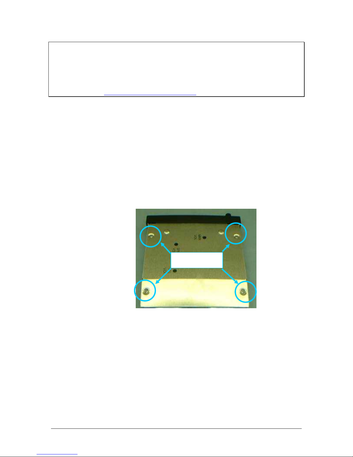
2.4.12.1 Public Address Output Jumper
1. Remove qty. 4 Phillip head screws from the PM8000BT. See Figure #1.
Figure 2-2 Screw Locations
2. Move the blue jumper located in the back corner near the sub-D connectors to the inboard two
pins of J4. See Figure #2-3.
Screws

PS Engineering
PMA8000BTi IntelliAudio Audio Selector Panel and Intercom System
Installation and Operator’s Manual
200-890-17221722 Page 2-7 Rev. 1, March 2016
Figure 2-3 Jumper Locations
4. Place the lid back on the unit, aligning holes.
5. Install and tighten qty. 4 long thread screws into the lid.
Public Address
Enabled
C
H
A
S
S
I
S
C
H
A
S
S
I
S
Public Address
Disabled
J4 Location
Public Address
Enabled
Public Address
Disabled

PS Engineering
PMA8000BTi IntelliAudio Audio Selector Panel and Intercom System
Installation and Operator’s Manual
200-890-17221722 Page 2-8 Rev. 1, March 2016
2.4.13 PA Mute (J2, Pin 12)
Pin 12 of J2 is a TTL logic output that is active low during PTT operation.
2.4.14 Miscellaneous Logic Output (J2, Pin 18)
Pin 18 of the J2 connector is pulled to ground whenever the AUX button is depressed. This serves as a co n-
trol line for external devices, such as an entertainment system that the pilot wishes to control.
This pin can also be used to control passenger (Music 2) Karaoke Mode, by connecting to pin 13 of the J2.
NOTE
J2, Pin 18 should NOT be used if the AUX is going to be used to switch DME or auxiliary audio.
2.4.15 Audio Active Output
Pin 24 on the J1 connector (and PA Mute Pin 12 on J2) should be connected to Apollo CNX80 for a udio
message prioritization, refer to CNX80 installation manual for details.
2.5 Intercom wiring
See Appendix C and D for intercom connection configurations. It is critical to the proper operation of this
system to have this connector wiring made in accordance with these diagrams. Use 2- and 3-conductor,
MIL-spec cable as shown. Connect the shields at the audio panel end only, and tie to the audio low inputs
as shown.
NOTE
The intercom harness can be custom made by PS Engineering, Inc. Simply call the factory o r www.ps-
engineering.com to obtain a wire harness work sheet. The harness will be made to your specifications and
fully functionally tested. Harness can be ordered with jack, or without the intercom jacks install ed, for easi-
er wire routing through the aircraft.
2.5.1 Entertainment Inputs
The PMA8000BTi has two INDEPENDENT music inputs, PLUS a front mounted jack that is connected to
Entertainment 1. Entertainment input number 1 is J2 pins 23 (left channel) and 24 (right channel), with
respect to pin 25, and Entertainment number 2 is connected to 26 (left channel), 27 (right channel), with
respect to 28.
PMA8000BTi has wireless connectivity to stream music from a paired Bluetooth device. This stream is
distributed as Music 1. Refer to §3.11.3 for more information.
NO TE
Us e the lo w level o utput of a ny a dditio na l enter tainment dev ic e to conne ct to the a u-
dio pa nel. Maximu m si gna l level i s 3 VAC p -p. DO NOT us e a spe a ker -le ve l o utput,
this will c a use inter nal damage i n the a ud io pa nel.
2.5.2 Entertainment muting
The PMA8000BTi incorporates a four-mode "Soft Mute™" system. This will mute the entertainment de-
vices during ICS and/or radio conversation. See Section 3.8 for more information.
Press the Mute switch to activate the four Karaoke modes (disabling crew SoftMute™). Turning down the
entertainment volume allows the pilot to place the entertainment into the background while having the r a-
dios in the foreground and eliminates the constant interruption of the music while still keeping the radios a
priority.
CAUTION
Local oscillators and internal signals from entertainment equipment can cause undesired interference with
other aircraft systems. Before takeoff, operate the entertainment devices to determine if there is any adverse
effect within the aircraft systems. If any unusual operation is noted in flight, immediately switch off the
entertainment devices.
All additional entertainment devices must be switched off for both takeoff and landing.

PS Engineering
PMA8000BTi IntelliAudio Audio Selector Panel and Intercom System
Installation and Operator’s Manual
200-890-17221722 Page 2-9 Rev. 1, March 2016
2.5.2.1 Entertainment 2 Mute (J2 Pin 13 & 14)
Connecting J2 pin 13 to pin 14 (or ground) through a SPST switch places the entertainment #2 music
source into the Karaoke Mode. In this mode, incoming music and intercom conversation will not mute the
music for the passengers’ intercom net. This allows uninterrupted music during casual conversation and at
times when radio communications are of lesser importance.
If desired, the AUX button can act as the passengers’ mute control. Connect J2 pin 18 (AUX logic) to J2
pin 13 (Entertainment. 2 Mute inhibit). Then, Entertainment 2 will not mute when the AUX button is on.
(Not recommended if DME is input is used.)
2.5.3 Configuring Music Input with Function Keys
The music inputs can be configured by the user from the front panel (see section 3.10). There are three co n-
figurations available, independent, ICS mode dependent, and single input (music 1 to all stations).
If the inputs are independent, Input #1 (or the front jack) is provided to the pilot and copilot. Muting
(SoftMute™) is controlled by the front panel “mute” button. Music 2 is provided to the passengers at all
times, with muting controlled by an external switch (see § 2.5.2.1).
If the inputs are intercom mode dependent, input 1 goes to the pilot, copilot, and all passengers when the
intercom is in the “ALL” mode. In “ISO” mode, the copilot and passengers will hear music input 1. Music
2 is ONLY active in CREW mode, and then provided only to the passengers. The externally switched pas-
senger SoftMute™ control becomes active in CREW.
If the single-source mode is activated through the function keys, the front panel jack (and music 1) is co n-
nected to all intercom positions, regardless of the intercom mode. Crew muting is controlled by the front
panel, passenger muting controlled through the switch. See section 3.11 for more details.
2.5.3.1 Annunciation and recorder playback
The pilot and copilot can hear the Function Key annunciations. If the customer wants to exclude playback
and function key annunciation playback from the copilot position, contact PS Engineering for more info r-
mation.
2.5.4 Playback button Installation
Internal Recorder can be played back from the front panel. A remote momentary, normally open (NO) push
button switch may be installed if desired to remotely activate the Recording System playback. This switch
can be located anywhere in cockpit convenient to the pilot's reach. The NO switch should be connected to
pin 22 of J2 of the PMA8000BTi, and ground. When installed, this button will act as in § 3.13.
2.6 Marker Beacon Installation
2.6.1 Marker Antenna Installation
A marker beacon antenna, appropriate to the type and speed of the aircraft, is required (not included). Refer
to aircraft and antenna manufacturer's installation instructions, as well as AC43.13 -2B (or later revision),
Chapter 3, for information on proper antenna installation techniques. The marker beacon antenna must be
mounted on the bottom of the aircraft.
2.6.2 External Marker Lights
For installations that require external marker beacon lights, there ar e three outputs that can drive 12-Volt
lamps only. The external output lamps are driven high (typically +7.0 VDC 4.0 VDC unloaded, at MAX
brightness) when active. Maximum source current per lamp is 125 mA. Voltage varies with photocell
dimming.
2.6.3 Middle Marker Sense
A Middle Marker Sense output signal is available from the PMA8000BTi to certain flight control systems.
This function will not operate during the test mode. This output will go to +4.5 VDC ( 1.0 VDC) when a
valid Middle Marker signal is received. This output is J1, pin 39.

PS Engineering
PMA8000BTi IntelliAudio Audio Selector Panel and Intercom System
Installation and Operator’s Manual
200-890-17221722 Page 2-10 Rev. 1, March 2016
2.7 Adjustments
The PMA8000BTi is factory adjusted to accommodate the typical requirements for most aircraft configur a-
tions. There are three adjustments in the top cover that allow the installer to tailor the specific functions.
Figure 2-4- PMA8000BTi Adjustments, top cover
Speaker Volume [SPR VOL] – Turn adjustment clockwise to increase cabin speaker output.
Marker Beacon Volume [MKR VOL] –, turn adjustment counterclockwise to increase marker
beacon audio level.
Annunciation Volume [ANN VOL] – Function Mode Annunciation Volume – controls the level of
the to access voice annunciations contained in the unit. (Top cover must be removed).
Unswitched Input 3 Volume [UNSW 3] – adjust from 50% to 200% of input value.
Dimmer [DIM]– Adjusts the brightness of the white text backlighting (no effect on the photocell
dimmed
2.8 Communications Antenna Installation Notes
For best results while in Split Mode, it is recommended that the one VHF communications antenna is locat-
ed on top of the aircraft while the other communications antenna is installed on the bottom. Any antenna
relocation must be accomplished in accordance with AC 43.13-2B, aircraft manufacturers’ recommenda-
tions and FAA-approved technical data.
WARNING
It is probable that radio interference will occur in the split mode when the frequencies of the two ai r-
craft radios are adjacent, and/or the antennas are physically close together. PS Engineering makes no
expressed or implied warranties regarding the suitability of the PMA8000BT in Split Mode.
Front of unit

PS Engineering
PMA8000BTi IntelliAudio Audio Selector Panel and Intercom System
Installation and Operator’s Manual
200-890-17221722 Page 2-11 Rev. 1, March 2016
2.9 PMA8000BTi Pin assignments
J1
Function
J2
Function
1
Mkr Ant
1
Pilot Phones Low
2
Mkr Ant Low
2
Copilot Phones Low
3
Telephone Audio in
3
Copilot Phones (L)
4
Telephone Low
4
Copilot Phones (R)
5
Telephone Mic Audio
5
Lights Low
6
Telephone Mic Key
6
14/28 V Lights
7
ADF Audio In
7
14/28 V Lights
8
ADF Audio Low
8
Aircraft Power
9
Com 1 Audio
9
Aircraft Power
10
Com 1 Audio Low
10
Aircraft Ground
11
Com 1 Mic
11
Aircraft Ground
12
Com 1 Mic Key
12
PA Mute
13
Com 2 Audio
13
Mute Inhibit
14
Com 2 Audio Low
14
Mute Inhibit Low
15
Com 2 Mic
15
Unswitched #4
16
No Connect
16
Pilot Phones (L)
17
Nav 1 Audio
17
No connect
18
Nav 1 Audio Low
18
Misc (AUX) logic output
19
Nav 2 Audio
19
PA Enable Output
20
Nav 2 Audio Low
20
Swap/ Remote ICS *
21
DME Audio
21
Swap Low
22
DME Audio Low
22
IRS Playback
23
Auxiliary Audio Input
23
Music 1 (L)
24
CNX80 Inhibit
24
Music 1 (R)
25
No connect
25
Music 1 Low
26
No connect
26
Music 2 (L)
27
Com 2 Speaker Load
27
Music 2 (R)
28
Com 2 Speaker Load
28
Music 2 Low
29
Unswitched Audio 3
29
No Connect
30
Com 2 Mic Key
30
No Connect
31
Unswitched # 1
31
Pilot Phones (R)
32
Unswitched #1 Low
32
Copilot Mic Audio
33
Pilot Mic Audio
33
Copilot Mic PTT
34
Pilot Mic PTT
34
Copilot Mic Low
35
Pilot Mic Low
35
Pass 1 Mic Audio
36
Ext IM MKR
36
Pass 1 Mic Audio Low
37
Ext OM MKR
37
Pass 2 Mic Audio
38
Ext MM MKR
38
Pass 2 Mic Audio Low
39
MM Sense
39
Pass 3 Mic Audio
40
Pass HP (L)
40
Pass 3 Mic Audio Low
41
Pass HP (R)
41
Pass 4 Mic Audio
42
Pass HP Low
42
Pass 4 Mic Audio Low
43
Unswitched #2 Low
43
Speaker Low
44
Unswitched #2 Audio
44
Speaker Output
*Serial Number BTi1083_ and above

PS Engineering
PMA8000BTi IntelliAudio Audio Selector Panel and Intercom System
Installation and Operator’s Manual
200-890-17221722 Page 2-12 Rev. 1, March 2016
2.10 Wiring Checkout
After wiring is complete, verify power is ONLY on pins 8 and 9 of the J2 and airframe ground on connect-
or pins 10 and 11. Failure to do so will cause serious internal damage and void PS Engineering's warranty.
2.11 Unit Installation
To install the PMA8000BT, gently slide the unit into the mounting rack until the hold-down screw is en-
gaged. While applying gentle pressure to the face of the unit, tighten the 3/32" hex -head in the center of the
unit until it is secure. DO NOT OVER TIGHTEN.
CAUTION
Apply steady pressure to the bezel while screwing the unit into the tray to ensure even seating of the unit
and connectors. WARNING Do not over-tighten the lock down screw while installing the unit in tray. In-
ternal damage will result.
2.12 Operational Checkout
2.12.1 Required Test Equipment
In order to return an aircraft to service after installation of the PMA8000BT, the installer must have access
to a Marker Beacon signal generator:
a. IFR NAV401L, NAV402AP, IFR4000
b. TIC T-30D, T-36C
Equivalent test equipment is acceptable as long as the testing requirements can be met.
2.12.2 Audio Panel Test
NOTE
The IntelliVox® is designed for ambient noise levels of 80 dB or above. Therefore some clipping may o c-
cur in a quiet cabin, such as without the engine running, in a hangar. This is normal .
1. Apply power to the aircraft and avionics.
2. Plug headsets into the pilot, copilot, and occupied passenger positions.
3. Verify fail-safe operation by receiving and transmitting on com 1 from the pilot position, with the au-
dio panel power off. The Com audio will be present in one ear cup only.
4. Switch on the unit by pressing the volume (VOL) knob.
5. Check intercom operation.
6. Push the Com 1 XMT select button (lower row).
7. Verify that both of the Com 1 buttons light. Verify that transmit button LED (Light Emitting Diode)
near the mic selector is not blinking unless the radio P-T-T is pressed. If the LED is blinking, stop test-
ing and troubleshoot the microphone PTT installation.
8. Verify proper transmit and receive operation from the copilot position, noting that the copilot PTT
switch allows proper transmission on the selected transceiver. Verify that the Com 1 Xmt button blinks
when transmitting.
9. Verify that pushing the COM 2button causes the button to illuminate, and the Com 2 receiver to be
heard. Verify operation on Com 1 from the pilot position.
10. Repeat for Com 2
11. Press and hold the Com 1 Xmt button. While holding the Com 1 button, press the Com 2 Xmt button.
This places the unit in “split Mode;” Verify that the pilot can transmit and receive on Com 1, while the
copilot transmits and receives on Com 2.
12. Verify proper operation of all receiver sources by selecting them using the appropriate button. The
button illuminates to show which source is in use.
13. Push the SPR button. Verify that all selected audio is heard in the cockpit speaker. Verify that the a u-
dio mutes when the mic is keyed.
14. Verify that the appropriate LED in the lower button row blinks when either push to talk is keyed.

PS Engineering
PMA8000BTi IntelliAudio Audio Selector Panel and Intercom System
Installation and Operator’s Manual
200-890-17221722 Page 2-13 Rev. 1, March 2016
15. Push both the RCV buttons at the same time to activate the IntelliAudio™ function. Verify that the
audio from COM 1 is present in the 10 o’clock headset position, and COM 2 is present in the 2 o’clock
headset position.
16. Verify proper Intercom system operation in the ALL, ISO and CREW modes (see Table 3-1).
17. Verify that the audio selector panel system does not adversely affect any other aircraft system by sys-
tematically switching the unit on and off, while monitoring the other avionics and electrical equipment
on the aircraft.
2.12.3 Marker Checkout
1. Connect a ramp generator at the antenna end of the marker coax. With the unit under test i n HI sensi-
tivity, verify that a 160 V, modulated 95% with 1300 Hz, signal will illuminate the amber (M) marker
light, and that marker audio is present in the headphones when the Marker Audio (M KR) push-button
has been depressed. Select SPR for speaker to verify marker audio availability on the cabin speaker.
Verify that the white (I) and blue (O) lights will illuminate within 3dB of the amber lamp, with 3000
HZ and 400 Hz applied, respectively.
2. Repeat with the unit in LOW sensitivity, with 430 Volts applied.
3. Connect the marker antenna and verify proper operation.
2.12.4 TEL Checkout
Press the TEL button. Verify that the pilot headset is connected to the cellular telephone system (if i n-
stalled). Verify that by using the pilot side PTT, the pilot can transmit on the other selected radio (Com 1 or
Com 2). The telephone function will allow any person heard by the pilot on the intercom, also heard on the
telephone.
2.12.4.1 Bluetooth Checkout (050-890-1722)
Verify that the PMA8000BT will “pair” with a Bluetooth device, and interface with cellular phone and
Music source. See section 3.12 for more information.
2.12.5 Internal Recorder Checkout
With headset plugged into pilot’s side jacks, tune COM 1 to local frequency, such as FSS or ATC ground.
Select Com 1 on mic selector switch, and record several incoming radio transmissions.
Press the Com receiver pushbutton that corresponds to the selected radio transmitter and hold for approxi-
mately one second. This action will then automatically play back the last recorded message. Press and
HOLD the button again to stop the play back, and then momentarily press again to play prior messages.
This audio should appear in the pilot and copilot headsets, and only be incoming transmissions from the
transceiver selected in the mic select switch. Depress the audio panel or yoke mounted playback switch,
and verify that messages play, in the order received. Repeat for COM 2. The playback will be stopped by
audio on the selected com. The message can be replayed from the beginning, and audio received during the
playback will not be stored.
2.12.6 Function Button Checkout
While listening to the pilot’s headset, press and hold the TEL, AUX, MUTE and SPR buttons, verifying
that the annunciations play back in pilot headset. See operation section for information. Incoming audio on
selected com will stop the audio.
Button
Announcement 1
Announcement 2
Announcement 3
TEL
Alternate Intercom Function
Standard Intercom Function
AUX
Monitor On
Monitor Off
MUTE
Music one all headsets
Alternate Music Distribution
Standard Music Distribution
SPR
Chime; music increases
Chime, music decreases
2.13 Final Inspection
Verify that the wiring is bundled away from all controls and no part of the installation interferes with ai r-
craft control operation. Move all controls through their full range while examining the installation to see
that no mechanical interference exists. Verify that the cables are secured to the aircraft structure in accor d-
ance with good practices, with adequate strain relief. Ensure that there are no kinks or s harp bends in the
Other manuals for PMA8000BTi
1
This manual suits for next models
1
Table of contents
Other PS Engineering Recording Equipment manuals

PS Engineering
PS Engineering PMA8000B--MP3 User manual

PS Engineering
PS Engineering PAC45L User manual

PS Engineering
PS Engineering PAC45T User guide

PS Engineering
PS Engineering PM1200 Manual

PS Engineering
PS Engineering PMA8000G User guide

PS Engineering
PS Engineering PAC45D User guide

PS Engineering
PS Engineering PAC15EX User guide

PS Engineering
PS Engineering PAC45 System With MultiTalker User guide

PS Engineering
PS Engineering PAR200B User guide

PS Engineering
PS Engineering PMA4000 TSO User manual


