PSC AlphaMix User manual

Photo Courtesy PSC
ALPHAMIXREVIEW
By Brandt Sleeper, MA
Media Producer & Sound Designer
President, Rising Eagle Productions, Fort Worth, TX
Adjunct Professor University of New Orleans & Art Institute of Dallas
AlphaMix™
The PSC AlphaMix is the latest edition to the
PSC line of mixers. This ENG/EFP1style
mixer is relatively small (approx. 10”X7”X2”;
4.25 lbs/1.9Kg) for the amount of flexibility it
offers. One of the first features you notice on
the AlphaMix is the ability to power the mixer
from an internally housed NP-1. The NP-1, a
format common to ENG/EFP video cameras,
is a high capacity rechargeable battery. If no
microphones are being powered, the AlphaMix
consumes only 210mA of current which translates to a 10 – 15 hour battery life2. If the
operator prefers they can opt to use 10x AA Alkaline batteries instead which supply the
standard 4 – 7 hours of operating time. Nevertheless, the NP-1 compatible design is
hard to beat.
Many ENG/EFP professionals use the NP-1 to externally power other mixers. The
difference with the AlphaMix is that the battery inserts directly into the unit. Typically an
operator would have to supply a specialized adapter and carry the battery separately
from the mixer. While this is not overly impractical, PSC has had the insight to
recognize the demand for the NP-1 format and employ the convenience of housing
long-life rechargeable batteries.
1The clarity of this mixer opens its application to location sound feature film work as well. Use of the expansion
port for a forthcoming two additional channels.
2Battery life with all mixers is dependent upon the number of devices that are drawing current from the battery. If
several powered microphones or wireless receivers are in use, the battery life will be reduced. It is also important to
realize that battery life varies significantly dependent upon the type of NP-1 used including: Ni-Cad, nickel Metal
Hydride and Lithium-Ion.

Input Side Panel
The input section of the AlphaMix is truly impressive for the price. This 4-channel mixer
begins with standard female XLR balanced inputs. PSC has developed an ultra low
noise input circuitry3in an effort to set new standards in field production equipment.
These inputs can be used at mic or line level and have an input range from -70dBu to
+4dBu. A toggle switch beneath each XLR input provide two level setting: “M” for
Microphone at 0dB attenuation; and “L” for line at 50dB attenuation.
Photo courtesy PSC
Microphone powering switches are also located below the XLR connectors and
provide standard Dynamic (D), Tornader 12-volt (T-series/AB) and 48-volt phantom
powering. The provision for T-series phantom powering is a welcomed return to this
common format for PSC. While T-series was available on the M4A+ it was not offered
on the MKm4II. As should always be the practice, the appropriate phantom power
should be used for each mic. When using line level, dynamic mics or wireless
receivers, the Dynamic (DYN) setting should be selected as no voltage is applied.
Another milestone for PSC is featured just above input Channel 1. Introduced with the
M4mkII, the AlphaMix offers a remote control of the boom audio level. This affects
Channel 1 only and offers the operator the capability of riding the level of the boom
input via a remote that can be mounted on the boom pole. This feature is very useful
when attempting to mix and boom simultaneously. Although not recommended, this
scenario is a common occurrence with ENG. It is quite difficult to boom with one hand
and mix with the other. The weight of the boom mic makes this practice a challenging
task. Typically, boom placement is compromised when the stabilizing hand is removed
to manipulate the mix. To overcome this limitation, PSC has had the foresight to design
a fader remote control that will strap directly on to the boom pole4. This control allows
an input control range of about 25dB. An LED on the front panel indicates that the
remote control is engaged which overrides the channel gain trim pot while in use.
31nV per root of the Hz.
4Setup directions are in the front panel gain control section, page (#).

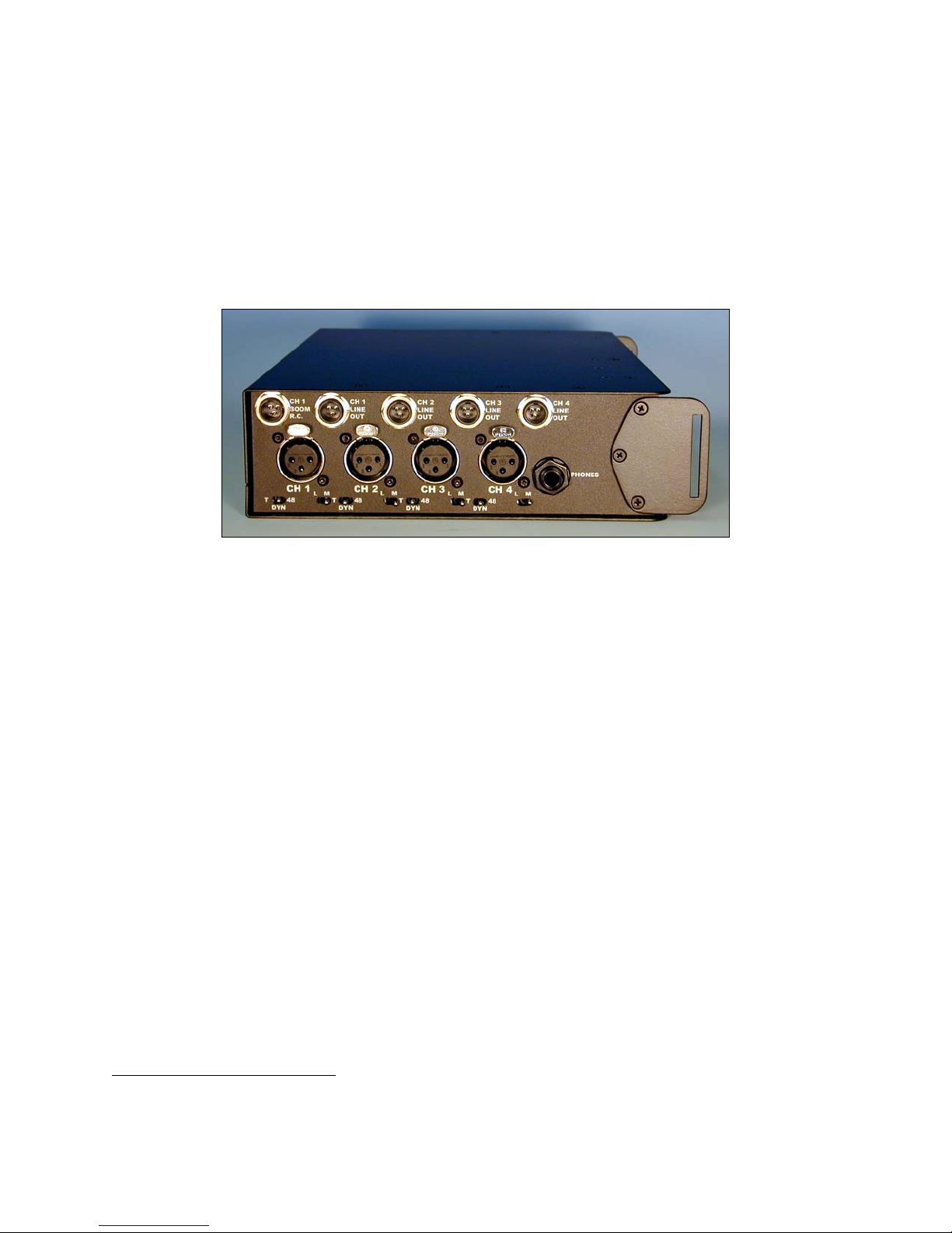
Although this is the input side of the mixer numerous outputs are located here as well.
The AlphaMix offers individual balanced outputs for each of the four channels. This
feature, rare in ENG mixers, is extremely useful for isolating the output of each channel.
Multiple microphone input mixing to mono or stereo output typically raises the noise
floor to unacceptable levels. In addition, mixing of signals renders absolute isolation of
each signal in post-production impossible. PSC has overcome this obstacle by
providing individual balanced outputs for each channel. With this flexibility, the operator
can send isolated channel program content to dedicated inputs on a single camera/VTR
or to multiple record units.
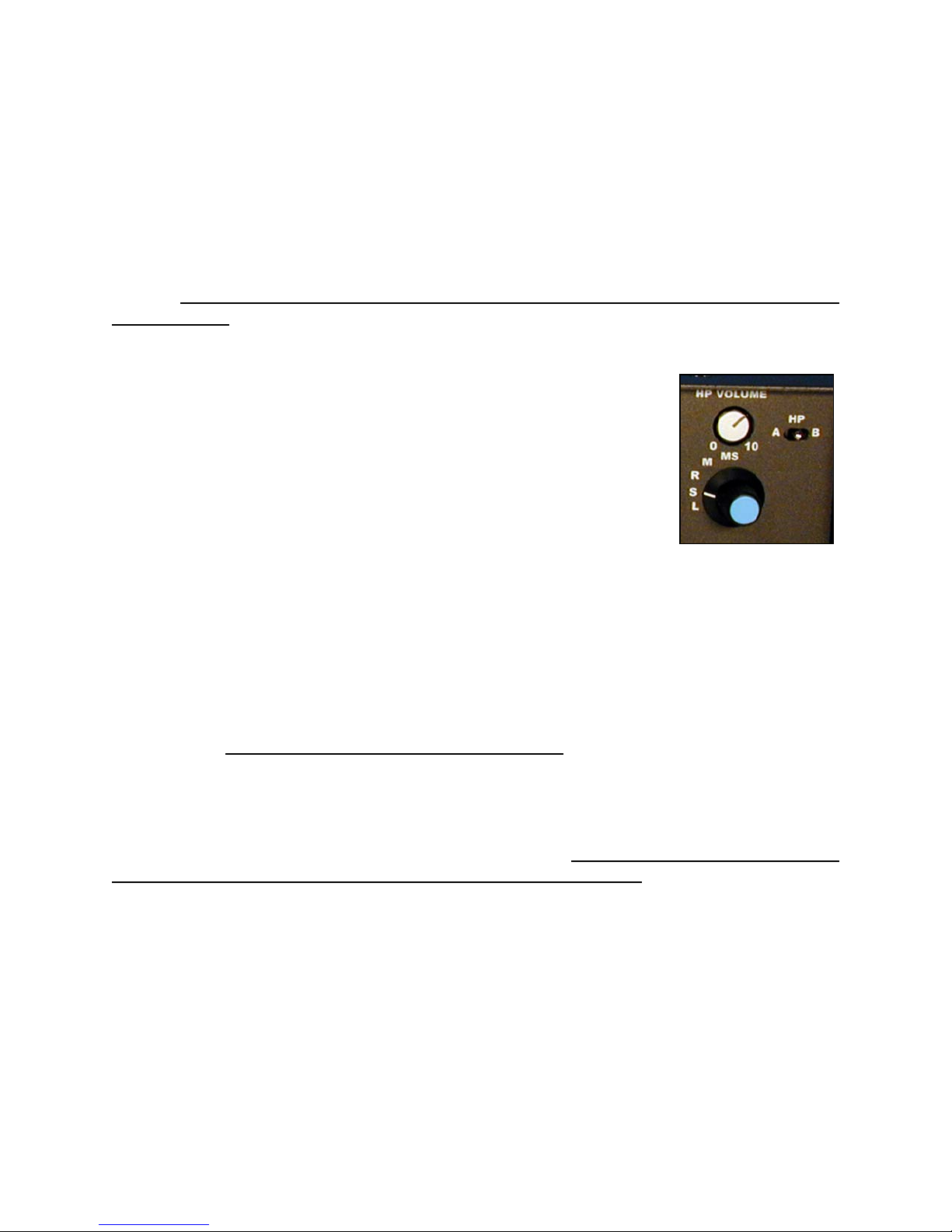
The monitor output (headphone) is located just to the right of XLR input for Channel 4.
This is a standard ¼” stereo headphone jack. The headphone amplifier circuitry will
drive most headphones within range of 32 – 600 Ohms impedance. The headphone
attenuator, monitor select rotary knob and source toggle are located on the front panel.
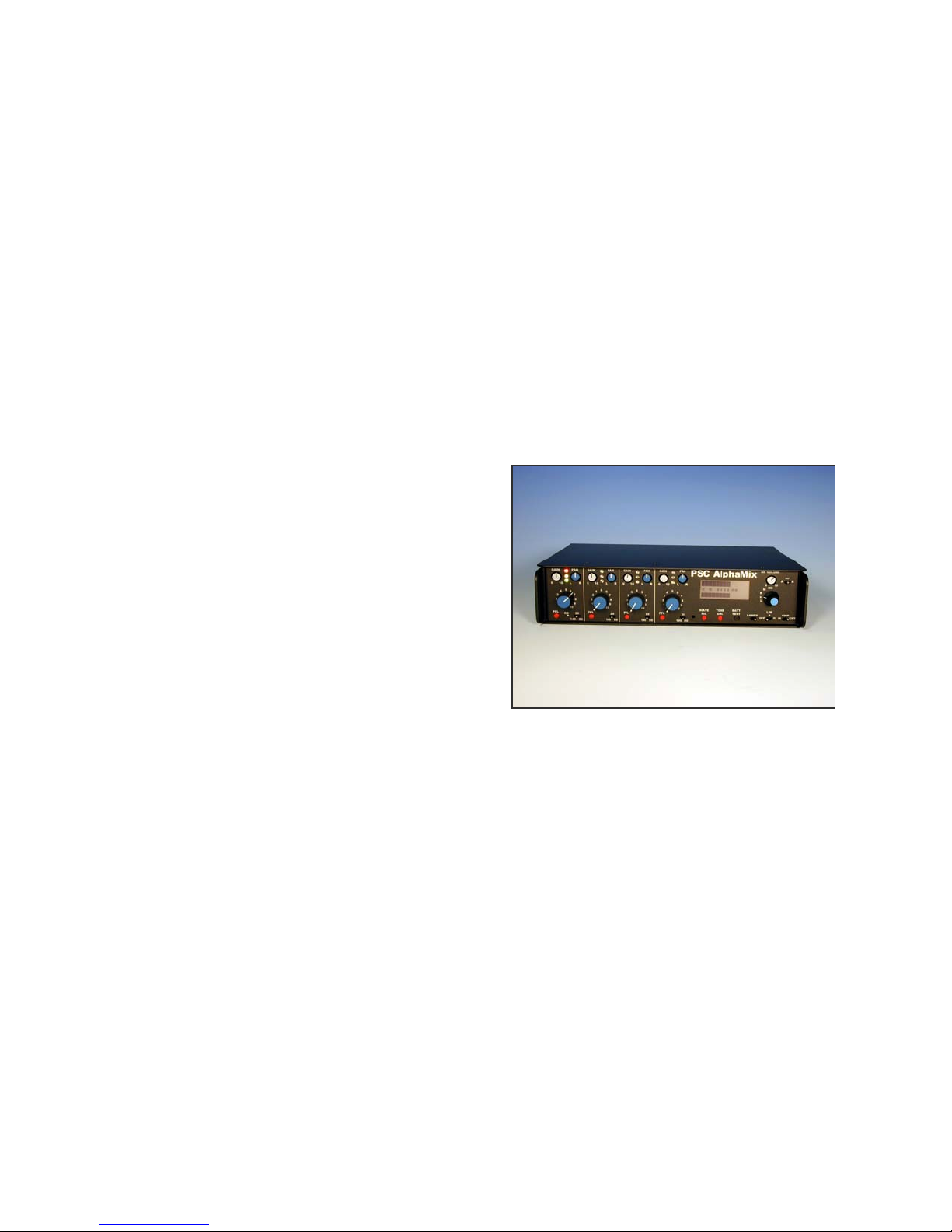
Front Panel
Experienced manufacturing becomes obvious when looking at the front panel of the
AlphaMix. The sleek design of this mixer is the result of years of design refinements.
Retractable channel gain, pan pot and headphone level controls greatly improve
operation; preventing unintended changes in the settings while in use. When needed,
these controls will pop up for access. The chassis features shields on either side of the
mixer protruding sufficiently to protect the mixer controls. The rigid aircraft aluminum
formed chassis provides significant resistance to torque. Housing parts are plated to
resist corrosion, and epoxy power coated for durability. All labeling is silk-screened
underneath a hard-face overlay that renders the labels virtually wear proof. The
advantage to this is readily obvious to operators who have faced the challenge of using
mixers with worn off faceplate labels.
All AlphaMix photos courtesy PSC
PSC has significantly improved the gain structure of the M4 series mixer with the
AlphaMix. The addition of retractable gain trims on each channel allows continuously
variable control of the input gain over a 40dB range. The signal flows from the
preamplifier to the low cut filters and then to the channel fader amplifier. Each channel
fader is in the feedback loop of the fader amplifier and thus controls the gain of the
amplifier rather than just serving as a rotary attenuator of the signal (standard volume
control). The AlphaMix is not equipped with a Master Fader. Research revealed that
less than 1% of the customers were using the master fader. By eliminating this non-
essential control, PSC was able to free up space for additional features5.
This gain structure, rare with mixers of this class, is additionally enhanced by the
presence of input channel metering. The green, yellow and red LEDs indicate pre-
fader audio level enabling the operator to preset channel gain levels prior to opening up
5Ron Meyer, President, PSC.

AlphaMix
remote
control
setup
procedure.
the attenuator. These LEDs are calibrated to reflect audio levels of -20dBu (green),
6dBu (yellow) and 0dBu (red). To properly set the input gain trim, the red LED should
just flash at the transient peaks of signal. For dialog, the green LED should remain lit
with occasional yellow presence at the peaks. Continuous red indicators are
representative of potential signal overload. These levels also indicate the output gain
level of the individual balanced outputs on the input side panel.
Just to the right of each gain control are the AlphaMix retracting pan pots.
These are equipped with center detents to confirm mid placement in the
summing output bus. As with any pan pots; the signal may be positioned as
desired within the stereo field. Once placement has been determined the
pots can be recessed to keep the front panel free from obstruction while
mixing.
The PFL button in the lower left corner is yet another feature uncommon to mixers in
this class. PFL allows the operator to monitor the signal prior to the Channel Gain. This
capability is critical in determining the quality of the incoming signal. It may also be
utilized when setting the Gain Trim level from an auditory context.
In the bottom right corner of each channel is the active low cut/high pass filter. This
three-position switch allows a 12dB per octave attenuation of all frequencies below the
preset frequency. The preset frequencies are at 80Hz (left position), 20Hz (center
position) and 140Hz (right position). If the 80Hz low cut is selected, there will be an
initial -3dB roll off at 80Hz. All frequencies below 80Hz will be rolled off at 12dB per
octave. The same applies to the 140Hz low cut application. When set at the middle or
“20Hz” position frequencies below 20Hz are rolled off with the AlphaMix operating at full
frequency response.
Centered below the Channel Gain6is the Remote Control indicator LED. This will
illuminate in the event that the remote control on the boom is employed indicating its
use. It is important to note that the use of the remote control overrides the channel gain
input trim pot. To properly utilize the remote control the following steps should be
observed:
1. Set mixer up as normal with appropriate microphone
power and channel fader off.
2. Attach remote control to the boom pole with strap.
3. Plug remote connector into mixer.7
4. Set slide fader to middle position and reopen channel
fader until meters register a normal signal.
5. Sliding knob toward the end of the cable lowers the
volume.
6. Sliding knob away from the cable end increases the
volume.
6Remote control featured on channel 1 only.
7See “Input Side Panel” photo page (#)

The boom remote offers a control range of approximately 25dB. Caution must be
observed before removing the remote control as high audio levels may occur should the
channel fader be anywhere near maximum level.
Viewing meter levels on the AlphaMix is very easy due to
the large LCD meter readout. PSC has designed these
peak-reading meters to emulate those of the Betacam.
The LCD meter provides additional information such as
Left and Right Limiter functions, battery life and Low
Battery Warning. The operator has approximately 15 – 30
minutes of remaining battery life when the “Low Bat”
indicator illuminates. In poor visibility and night viewing
situations meter lamps are available. PSC chose a woven
fiber optic light transmission panel with a high performance “green” LED as a light
source rather than an electro-luminescent system. The combined approaches yield
quality backlighting without introducing noise. To activate the lamps there is a toggle
switch located below the bottom right corner of the meter.
Directly below the meters you will find the Slate Microphone (SLATE MIC) button.
When this momentary push button is depressed the slate microphone is activated. The
electrete variable gain microphone is located just to the left of the button. A really nice
function of this switch is that it automatically mutes the input channels. This eliminates
the need to pot down the input channels in order to eliminate unwanted audio. The
hidden benefit is that potting down the inputs effectively destroys any mix the operator
may have previously established. Such practice will waste valuable time and render
continuity virtually impossible. A trim pot is located on the bottom panel for level
adjustment of the Slate Mic.
To the right of the Slate Mic is the Tone Oscillator (TONE OSC). PSC chose a
reference frequency of 440Hz rather than the more common 1kHz. The rationale
behind this was that the 1kHz tone was particularly harsh to the ears. More often than
not, tone is turned on while someone is auditioning the mixer. While this is probably
unintentional it can be very irritating to be hit with a 1kHz tone at 0dB. Since all that is
required to calibrate the various metering systems in the chain is a pure tone, the
frequency is not particularly relevant. A trim pot is located on the bottom panel for level
adjustment of the tone oscillator.
Next in line with the Tone Osc is the Battery Test (BATT TEST) button. Depressing
this momentary button causes the top (left) meter to display the remaining life
expectancy of the battery. The length of the bar is directly proportional to the life of the
battery. A full bar would indicate a full battery, a half-bar suggests a half-full battery and
so forth. NP-1 batteries are available in a number of formats8. Therein, PSC has
installed a selector on the bottom panel of the AlphaMix that will adjust the function of
the battery test feature specific to the NP-1 type.
8Ni-Cad, Nickel Metal Hydride and Lithium-Ion.

To the left of the Lamps switch is the Output Limiter (LIM) three-position switch. The
setting of this switch (Off, “S” separate, or “G” ganged) determines the limiting function.
Two independent and separate limiters are built into the AlphaMix; particularly useful
when recording split tracks. This allows one limiter to engage when the limit threshold
(+3 on the meter) is reached. If the other channel remains below threshold it will not
engage. The compression ratio of the limiter is approximately 2.7 to 1 with a 1mS
attack time and 100mS release. The presence of output limiting is displayed on the
meter. PSC recommends use of the limiters at all times when recording to Betacam
type cameras.
The last switch on the lower left of the front panel is the Power (PWR) switch. This two-
position switch selects the power source. The AlphaMix can be
powered from an internal battery (IN) or an external source (EXT).
Headphone output function controls are located on the upper
right corner directly above the LIM switch. These controls consist
of a recessing output volume (HP VOLUME) pot, a source toggle
switch (HP) and a rotary mix select switch. The headphone
circuitry of the AlphaMix will drive most any headphone with
impedance of 32 to 600 Ohms.
After setting the desired headphone level, the rotary HP VOLUME pot can be recessed
to prevent accidental changes. To the right of the volume pot is the three-position
source toggle switch (labeled HP). This switch enables the operator to monitor the
AlphaMix’s tape returns. Tape returns arrive through the Hirose™ 10-pin connectors on
the Output Panel. In the center “D” position the operator is able to monitor the mixer
directly. Positions “A” and “B” monitor camera/recorder returns. “A” and “B” levels can
be adjusted to match the signal levels of most any device using a small jeweler’s
screwdriver. Levels are adjusted on the bottom panel. Below the HP VOLUME pot is
the mix selector (not labeled). This 5-position rotary switch determines the monitoring
of Left only (L), Stereo L/R (S), Right only (R), mono (M) or Mid Side Stereo (MS).
When recording stereo X-Y or M-S signals the headphone mix selector should be set
in the Stereo or MS position respectively. Additionally, the input-ganging switch located
on the bottom of the mixer must be set to the “ganged” position. This allows the inputs
of channels 3 and 4 to be ganged enabling both channels to be controlled by pot 4.
With either type of stereo mixing, the pan pots for channels 3 and 4 remain independent
and should be panned hard L (3) and R (4). When recording X-Y stereo; identical
microphones are plugged into channels 3 and 4. M-S stereo recording requires that the
middle “M” microphone (cardioid) is plugged into channel 3 and the “S” side microphone
(bi-directional) be plugged into channel 4. The headphone amplifiers receive MS
decoded signals that appear as standard stereo audio for monitoring without affecting
the main XLR outputs.

Output Panel
PSC has really put
some thought in the
output capabilities of
the AlphaMix. It is
remarkable that the
output section of this
mixer supplies 3
balanced stereo
outputs, 2 TRS
stereo outputs and 1
mono output in
addition to the 4
direct outputs on the
Input Panel. The AlphaMix features dual isolated audio output transformers designed to
supply wide bandwidth and low distortion and interface with virtually any other device
including wireless transmitters. Furthermore, the dual transformers allow operator to
feed two cameras without interference.
Centered on the output panel are two 10 pin Hirose™ camera connectors. This
connector supplies balanced outputs for both left and right channels and provides tape
monitor returns. CAMERA A sends the same information as the L/R XLR outputs
located to the right of the Hirose connectors. Toggle switches below the XLR outputs
determine whether the signals for the XLR’s and CAMERA are at line level (+0dBv into
10k Ohm9loads) or mic level (-50dBv). CAMERA B is isolated electronically from
CAMERA A and is independently switched to line or mic level via the toggle switched
located below the output.
The AUXILARY OUTPUTS located above the right main XLR output are intended for
transcription. Both outputs are stereo 3.5mm TRS connectors wired: Tip = Left, Ring =
Right and Sleeve = Ground. These switchable outputs are located on the top panel
near the right side, just above the AUX OUT connectors. They will supply either line
level at -10dBv or mic level at -50dBv. If desired, the XLRs themselves could be used
in place of or in conjunction with the stereo mini-jack for DAT or audio tape recording.
In the upper left corner PSC has installed two multi-pin mini-jacks outputs. The 3-pin
jack supplies a balanced mono feed (labeled OUT). This is quite useful in sending a
wireless IFB feed to a producer, teleprompter or boom operator. Adjacent to the mono
feed is a 5-pin GANG output. This is an expansion port for future PSC accessories
including a soon to be released 2 channel expansion module that will increase the input
capability of the AlphaMix to 6.
The upper right corner features 4 auxiliary power outputs (AUX PWR OUT) to power
wireless transmitters. An ENG/EFP audio package typically includes 4 such
9The typical load imposed by most Betacams and other devices is 10K Ohms.

transmitters that have traditionally required specialized adapters that attach to external
batteries. PSC has effectively eliminated the need for this additional hardware with
these auxiliary power supplies. The NP-1 battery receptacle is located in the bottom
right corner. This receptacle will also accept 10 AA alkaline batteries housed in a
battery tray designed to be inserted into the NP-1 battery slot. PSC doe not
recommend that alkaline batteries be used when powering wireless receivers; however,
as they will not deliver enough power to simultaneously operate the mixer and the
receivers. External power supplies can be introduced through the Hirose™ 4-pin plug
located in the lower right corner. The pin configuration of this connector is Pin 4 (+,
positive) and Pin 1 (-, negative) and accepts DC power from 10 – 18 Vdc. This DC
input is protected from reverse polarity to that the mixer will not be damaged from
inadvertent polarity mismatch. In the event of reverse polarity the mixer will simply not
power up.
Conclusion
PSC has set numerous benchmarks with the AlphaMix ensuring that it will be a
dominant force among ENG/EFP mixers in its class. The ergonomic design allows ease
of operation and accessibility to all critical switches from the outside of the mixer. A
small number of switches are located on the bottom of the mixer; however, the need to
adjust these controls is rare. In the event that they do need adjustment they can be
easily accessed by slipping the mixer out of its carrying case. Numerous PSC
exclusives have been unveiled with this versatile mixer that set it apart from other
mixers in its class including:
1. Very low noise preamplifiers.
2. 3 LED meters on each input channel.
3. Remote control slide fader that boom mounts.
4. Dual Hirose™ 10 pin connectors for multi-camera feed.
5. Balance mono output.
6. Internal NP-1 receptacle
7. Built-in and calibration switchable battery monitor.
8. Custom LCD peak meters that emulate Camcorders.
9. Wear-proof subsurface silk-screening.
Other manuals for AlphaMix
1
Table of contents