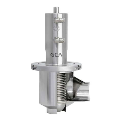
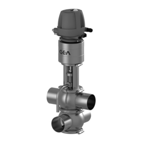
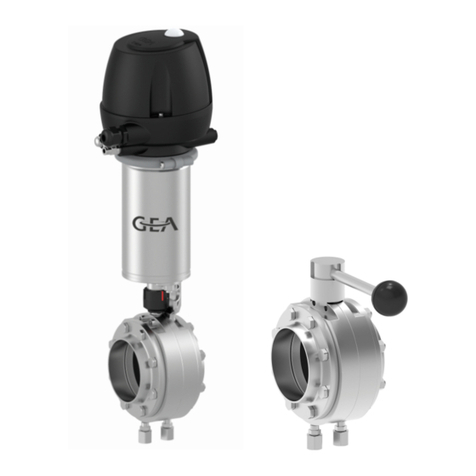
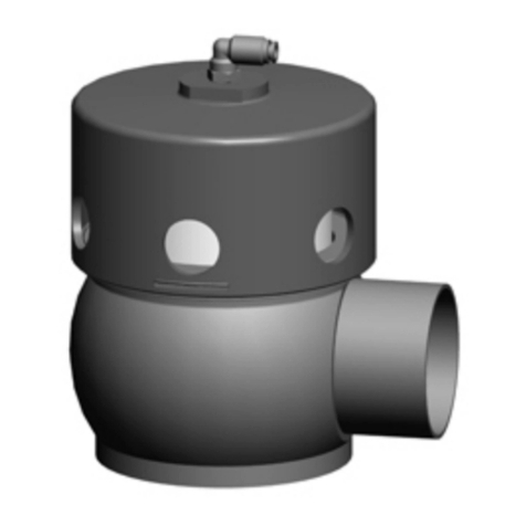
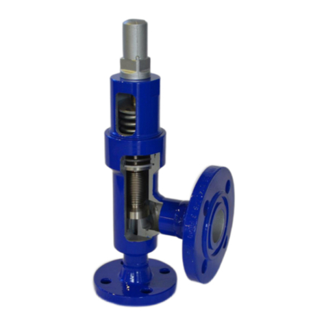
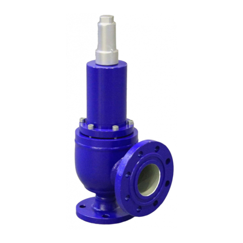
GEA ECOVENT TEFASEP-Gold ECO E User manual

Hygienic valves
GEA ECOVENT® accessories - angle seat valve_TEFASEP-Gold
Assembling Instruction (Translation from the original language)
221BAL015386EN_1

COPYRIGHT
These Operating Instructions are the English translation of the original operating instructions in the
sense of the EU Machinery Directive. This document is protected by copyright. All rights reserved.
The document may not, in whole or in part, be copied, reproduced, translated or reduced to an
electronic medium of machine-readable form without the express permission of GEA Tuchenhagen
GmbH.
LEGAL NOTICE
Word marks
The designation VARIVENT® is a protected trademark of GEA Tuchenhagen GmbH.
221BAL015386EN_1
2 01.11.2023

TABLE OF CONTENTS
1 General Information 5
1.1 Information about this document 5
2 Safety 6
2.1 Intended use 6
3 Technical data 7
3.1 Technical data 7
3.2 Tightening torques for the hinged clamps/ cast C-rings 8
4 Tefasep Gold 9
4.1 Note 9
4.2 Servicing intervals 10
4.3 Exchanging the O-ring (TEFASEP gold) 11
5 Spare parts list - angle seat valve ECO NI 13
6 Dimension sheet - angle seat valve_ECO E 15
221BAL015386EN_1
01.11.2023 3

221BAL015386EN_1
4 01.11.2023

1 General Information
1.1 Information about this document
These additional operating instructions are part of the user information for the valve.
These additional operating instructions contain the manufacturer's instructions to the operator of
the valve and to all persons who work on or use the valve regarding the procedures to follow.
They include basic instructions for use of the valves. This document is a supplement to the general
standard operating instructions for the ECOVENT angle seat valves and is therefore to be
considered part of it.
These additional operating instructions must be observed before installation and commissioning.
General Information
Information about this document
221BAL015386EN_1
01.11.2023 5

2 Safety
2.1 Intended use
The valve is used for opening and closing pipeline sections.
Proper use of the valve also includes compliance with these operating instructions.
The medium should preferably flow in the opening direction of the valve disk to avoid pipe
hammers when the valve is opened or closed.
In a closed pipe system, hydraulic pressure build-up may occur when the valve switches and result
in seal damage.
Hint!
The manufacturer will not accept any liability for damage resulting from any use of the
valve which is not in accordance with the designated use of the valve. The risk is
borne solely by the operating company.
Safety
Intended use
221BAL015386EN_1
6 01.11.2023

3 Technical data
3.1 Technical data
Refer to the following tables for the key technical data of the valve:
Technical data: Valve
Designation Description
Size 4" to 6" OD
Material of product contact parts Stainless steel 1.4404
Fitting position Any position, if valve and pipe system can drain
properly
Technical data: Ambient temperatures
Designation Description
Valve
0 to 45 °C (32 ... 113 °F), standard
< 0 °C (32 °F): Use control air with low dew
point. Protect valve rods against freezing.
< −15 °C: no solenoid valves in the control top
Initiator -20 to +80 °C (-4 ... +176 °F)
Product temperature and operating temperature depending on the sealing material
Technical data: Compressed air supply, product pressure
Designation Description
Air hose
•Metric Material PE-LD Outer-Ø 6 mm +/- 0.1 mm
Inside Ø 4 mm
•Inch Material PA outer-Ø 6.35 mm +/- 0.1 mm
Inside Ø 4.3 mm
Control air acc. to ISO 8573-1
•Solid particle content:
Quality class 6
Particle size max. 5 µm
Particle density max. 5 mg/m3
•Water content:
Quality class 4
max. dew point +3 °C
If the unit is used at higher altitudes or at low
ambient temperatures, the dew point must be
adapted accordingly.
•Oil content:
Quality class 3,
preferably oil free
max. 1 mg oil to 1 m3 air
Technical data
Technical data
221BAL015386EN_1
01.11.2023 7

Technical data: Compressed air supply, product pressure
Designation Description
Control air pressure
6 bar (87 psi), max. 8 bar (116 psi)
configuration with standard drive
Alternative combinations of product pressure
and control air pressure on request
Product pressure 2 bar (30 psi) configuration with standard
actuator
3.2 Tightening torques for the hinged clamps/ cast C-rings
Tighten the nuts of the hinged clamps to the tightening torques specified in the table.
Required tightening torques
Size [Nm] [lbft] Valve stroke [c]
4'' OD 22 15.4 155mm
6'' OD 45 31.5 230mm
- Check function
- Actuate valve with compressed air
- Check whether the valve stroke (c) is correct
Fig.1
Technical data
Tightening torques for the hinged clamps/ cast C-rings
221BAL015386EN_1
8 01.11.2023

4 Tefasep Gold
4.1 Note
Hint!
TEFASEP gold valve seat seals achieve optimal sealing only after an initial CIP or SIP
cleaning.
CIP or SIP cleaning operating conditions:
-Medium: lye, hot water or saturated steam
- Temperature: >80 °C (176 °F)
- Hold time: 20 … 30 min
The valve must be brought to the closed position for a brief period (3 minutes)
immediately after CIP or SIP cleaning.
During commissioning, regularly check all sealing points for leaks.
Exchange defective seals and repeat the CIP or SIP process.
Tefasep Gold
Note
221BAL015386EN_1
01.11.2023 9

4.2 Servicing intervals
To ensure the highest operational reliability, all wearing parts should be replaced at longer
intervals.
The actual servicing intervals can only be determined by the user since they depend on the
operating conditions, for instance:
•daily period of use,
•switching frequency,
•type and temperature of the product,
•type and temperature of the cleaning solution,
•ambient conditions.
Servicing intervals
Applications Servicing Intervals (Guideline Values)
Elastomers
Servicing Intervals (Guideline Values)
TEFASEP gold (hard seal)
Media at temperatures of
60 °C to 130 °C
(140 °F to 266 °F)
approx. every 3 months approx. every 12 months
Media at temperatures of
< 60 °C
(< 140 °F)
approx. every 12 months approx. every 12 months
Tefasep Gold
Servicing intervals
221BAL015386EN_1
10 01.11.2023

4.3 Exchanging the O-ring (TEFASEP gold)
Tools required:
•O-ring cutter
•Heat-resistant protective gloves
•Oven (no microwave)
Caution!
Health hazard due to toxic fumes!
The O-ring cutter cuts the seal with a hot metal tip. At temperatures of more than 300 °C,
toxic fumes can be released.
► Avoid directly inhaling the fumes.
Caution!
Risk of injury due to hot and sharp-edged parts!
The O-ring cutter cuts the seal with a hot metal tip. This process heats up the seal and
possibly also metal parts of the valve.
► When removing the valve seat seal always wear heat-resistant protective gloves.
Carry out the following steps:
1. Place the heated metal tip of the O-ring cutter at right angles on the valve seat seal to be
removed.
2. Cut through the valve seat seal at one point using the O-ring cutter.
! Pay attention not to damage the edge of the radial groove.
Fig.2
3. Take out the cut valve seat seal.
4. Warm a new O-ring (TEFASEP gold valve seat seal) in the oven.
Temperature . . . . . . . . . . . . . . . . . . . . . . . . . . . . . . . . 140 °C (guideline value)
Time . . . . . . . . . . . . . . . . . . . . . . . . . . . . . . . . . . . . . . 3 - 5 minutes (guideline value)
! Ensure that the seal can be deformed along the circumference without much effort. The
heating time required depends on the type of oven and can vary accordingly.
Tefasep Gold
Exchanging the O-ring (TEFASEP gold)
221BAL015386EN_1
01.11.2023 11

Fig.3
5. Use both thumbs to press the heated O-ring (TEFASEP gold valve seat seal) into the radial
groove at one point.
Fig.4
6. Then use both palms to press the valve seat seal in place in the radial groove.
! Make sure the valve seat seal "clicks" into the radial groove. The audible clicking noise
indicates that the seal has been fitted correctly.
! The valve may not be totally leak-proof after a new TEFASEP gold valve seat seal has been
fitted. The valve seat seal will adjust itself optimally to the sealing surfaces only after the first
CIP or SIP cleaning (see ) and will then guarantee perfect sealing up to the maximum closing
pressure or vacuum.
Fig.5
? The valve seat seal is still too rigid and cannot be mounted?
®Heat the valve seat seal again as described in the first step.
? When installing the valve seat seal, the seal does not "click" into place any more?
The valve seat seal has been overheated and can no longer be used.
®Repeat the operation with a new valve seat seal.
®Observe the data specified for heating the valve seat seal.
®The valve seat seal has been removed.
Tefasep Gold
221BAL015386EN_1
12 01.11.2023

5 Spare parts list - angle seat valve ECO NI
Fig.6
Spare parts list - angle seat valve ECO NI
221BAL015386EN_1
01.11.2023 13

Item Designation Material 4" OD 6" OD
1* Seal ring EPDM 924-085 924-085
FKM 924-083 924-083
2* Bearing PTFE/carbon 935-088 935-003
Bearing, 3A PEEK450G 935-100 935-102
3 Seal disk 1.4404 221-141.15 221-141.66
4 Locking ring 1.4301 221-641.04 221-641.05
5* O-ring EPDM 930-156 930-260
FKM 930-178 930-259
7* V-ring EPDM 932-028 932-042
FKM 932-039 932-041
7.1* O-ring Tefasep gold 930-103 930-1082
9 Lantern 1.4301 221-638.05 221-638.10
10 Retaining ring 1.4301 221-003957 221-007708
15 Valve disk NI 1.4404 221-002676 --
15.1 Valve disk NI-TS 1.4404 221-639.25 221-639.24
29* O-ring NBR 930-026 930-026
43 Clamp join KL -- 221-507.11 221-507.14
59 Plain bearing IGLIDUR-X 704-044 704-042
61 Screw-in plug connection
G1/8"-6.35/4.31
Brass/nickel-plated 933-144 933-144
Elbow screw-in plug connection G1/8"-6.3 Brass/nickel-plated 933-979 933-979
61.1 Reducing nipple NPT 1.4305 933-962 933-962
98* O-ring NBR 930-046 930-059
140 Drive ECO -- 221-642.14 221-642.25
NI housing 1.4404/316L 221-002649 221-007731
Housing NI_C (with 1"CIP clamp connection) 1.4404/316L 221-007710 --
402 Housing NI_C (with 2"CIP clamp connection) 1.4404/316L 221-005155 221-007682
Blanking plate ECO-E
Blanking plate ECO-E cpl. 1.4301 221-643.21 221-643.30
98* O-ring NBR 930-046 930-059
202.1 Plain bearing IGLIDUR-X 704-044 704-042
* Items marked with an * are wearing parts
Spare parts list - angle seat valve ECO NI
221BAL015386EN_1
14 01.11.2023

6 Dimension sheet - angle seat valve_ECO E
Fig.7
Dimension sheet - angle seat valve_ECO E
221BAL015386EN_1
01.11.2023 15

Dimension 4'' OD 6'' OD
B [mm] 733 945
B1 [mm] 829 1105
Ø 101.6 x 2.1 152.4 x 2.7
C [mm] 360 500
D 170 170
H [mm] 576 722
H1 641 842
C 79.5 118.5
Stroke S [mm] 155 230
Weight [kg] 40.0 59.6
Dimension sheet - angle seat valve_ECO E
221BAL015386EN_1
16 01.11.2023

Dimension sheet - angle seat valve_ECO E
221BAL015386EN_1
01.11.2023 17

This manual suits for next models
1
Table of contents
Other GEA Control Unit manuals
Popular Control Unit manuals by other brands

NewMar
NewMar BMS-19/23 Installation & operation manual

Telit Wireless Solutions
Telit Wireless Solutions UE910 series Hardware user's guide

Enclustra
Enclustra Mercury+ XU8 SoC user manual

Comunello
Comunello QUAD - 24V - 2M Installation and user manual

CZH-LABS
CZH-LABS F-1013 manual

ADTRAN
ADTRAN Octal E&M user manual