2. Retirer la plaque murale et l’interrupteur existant, le cas échéant.
3. Dénuder l’extrémitéde chaque fil du circuit afin d’exposer 1.6 cm (0,63 po) de cuivre; s’assurer que les brins soient bien droits.
4. Raccorder les fils conformément au SCHÉMA DE CÂBLAGE et de la façon suivante : entortiller fermement les brins de chaque fil et les enfoncer, avec le conducteur de circuit approprié, dans des serre-fils de format
convenable; tourner ces derniers vers la droite en s’assurant qu’aucun brin ne dépasse; protéger les raccords au moyen de ruban isolant.
IMPORTANT : ce modéle est dotéd’un réglage de compensation qui permet àl’installateur de fixer avec précision l’extrémitéinférieure de la plage de vitesse de ventilateur selon les bosoins de l’application. Dans la
plupart des cas, la valeur attribuée par l’usine devrait convenir (passer alors tout de suite àl’étape 8), mais si on doit la modifier, on doit suivre las étapes ci-dessous.
5. Rétablir l’alimentation au fusible ou au disjoncteur. Tenir solidement la commande par son boîtier isolé, la bascule vers le bas. S’assurer que le ventilateur tourne en mettant cette bascule àla position sous tension (ON) et en
plaçant la glissière vers le centre de sa course. (Située sous la glissière, la bascule sert àmettre en marche et àarrêter le ventilateur.)
6. Le réglage de la vitesse minimale se trouve sur la partie supérieure du couvercle arrière du dispositif. Mettre la bascule hors tension (OFF) et abaisser la glissière àson point le plus bas (le plus près de la bascule).
7. Lorsque ses pales ne tourneront plus, faites redémarrer le ventilateur en mettant l’interrupteur MARCHE/ARRÊT àbascule àla position «ON»(laissez le régulateur àla position plus basse); le ventilateur devrait alors
tourner ¡a sa plus basse vitesse; si les pales ne tournent pas, réglez la vitesse minimale du ventilateur comme suit :
A. Insérer un petit tournevis dans la fente de réglage.
B. Tourner dans le sens de aiguilles d’une montre pour augmenter la vitesse, el dans le sens contraire pour la réduire; la vitesse de l’appareil devrait être réglée au plus bas.
8. COUPER L’ALIMENTATION; enfoncer délicatement les fils dans la boîte murale en prévoyant suffisamment d’espace pour le commande de vitesse; installer ce dernier au moyen des vis d’assemblage fournies; fixer
la plaque murale.
9. Rétablir le courant au fusible ou au disjoncteur; L’INSTALLATION EST TERMINÉE.
FONCTIONNEMENT
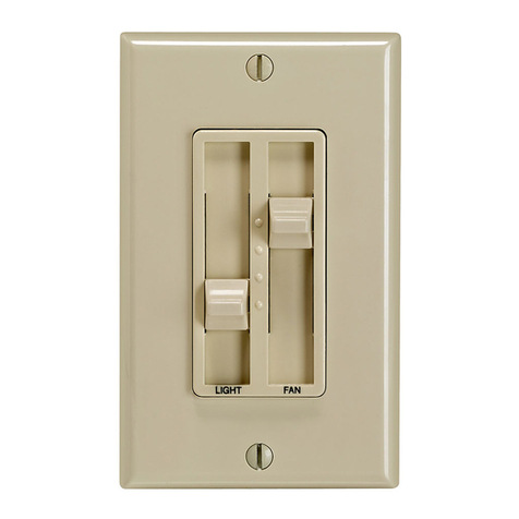
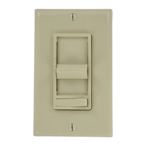
Ajustez la vitesse du ventilateur en faisant glisser le régulateur de vitesse de haut a bas; l’interrupteur MARCHE/ARRÊT àbascule permet de démarrer le ventilateur àla vitesse indiqués par le régulateur.
Español
CARACTERISTICAS
•Diseño de estilo Decora®de Leviton •Control deslizante para operación fácil y precisa
•Opera cualquier número de ventiladores de techo que no pasen sus límites de capacidad •Ajuste de Velocidad Mínima
•Cabe en cajas de pared estándar
INSTRUCCIONES DE INSTALACION
ADVERTENCIA: PARA INSTALARSE Y/O USARSE DE ACUERDO CON LOS CODIGOS ELECTRICOS Y NORMAS APROPIADOS.
ADVERTENCIA: SI USTED NO ESTA SEGURO ACERCA DE ALGUNA DE LAS PARTES DE ESTAS INSTRUCCIONES, CONSULTE A UN ELECTRICISTA CALIFICADO.
ADVERTENCIA: PARA EVITAR SOBRECALENTAMIENTO Y POSIBLE DAÑO A ESTE APARATO Y OTRO EQUIPO, NO INSTALE PARA CONTROLAR UN RECEPTACULO, ALUMBRADO FLUORESCENTE O
PRODUCTOS QUE OPERAN CON MOTOR O TRANSFORMADOR DIFERENTES A LOS APROPIADOS PARA VENTILADORES PARA TECHO.
ADVERTENCIA: PARA REDUCIR EL RIESGO DE FUEGO O CHOQUE ELECTRICO, ESTE CONTROL ES PARA USARSE CON UN VENTILADOR PARA TECHO QUE SEA ADECUADO PARA USARSE CON UN
CONTROL DE VELOCIDAD CON SEMICONDUCTORES CON CAPACIDAD DE 120 VOLTIOS, 5 A MAXIMO.
ADVERTENCIA: PARA USARSE SOLO EN VENTILADORES DE PALETA PARA TECHO CON MOTORES DE POLOS PROTEGIDOS O DE CAPACITOR DIVIDIDO. FAVOR DE VER LAS INSTRUCCIONES DEL
FABRICANTE DEL VENTILADOR O LAS ETIQUETAS DE CAPACIDADES EN EL MOTOR PARA CONFIRMAR EL TIPO. EL USO CON CUALQUIER OTRO TIPO DE MOTOR PUEDE CAUSAR
SOBRECALENTAMIENTO Y/O DAÑO AL MOTOR O EQUIPO.
OTRAS PRECAUCIONES:
1. USE SOLO UN CONTROL DE VELOCIDAD EN UN CIRCUITO DE 3 VIAS. EL INTERRUPTOR DE 3 VIAS QUE QUEDA ENCENDERA EL VENTILADOR A LA VELOCIDAD FIJADA POR EL CONTROL.
2. DESCONECTE LA ENERGÍA CUANDO LE DE SERVICIO A LOS APARATOS.
3. USE ESTE PRODUCTO SOLO CON CABLE DE COBRE O REVESTIDO DE COBRE. PARA CABLE DE ALUMINIO USE SOLO PRODUCTOS MARCADOS CON EL SIMBOLO CO/ALR O CU/AL.
CONTROL DE MULTIPLES VENTILADORES:
Cualquier número de ventiladores del mismo tipo pueden ser controlados por un solo control de velocidad a condición de que el amperaje total de los ventiladores no exceda la capacidad de amperaje del control de
velocidad para ventilador.
COMBINACION/REDUCCION DE CAPACIDAD: Cuando se instalen combinaciones de atenuadores y/o controles de velocidad en una caja, se requiere reducción de capacidad. Cuando dos unidades estén montadas en
una caja, la carga máxima por aparato no debe exceder de 4.1A o 500 W. Cuando tres o más unidades estén montadas en una caja, la carga máxima no debe exceder 3.3A o 400 W.
PARA INSTALAR:
1. ADVERTENCIA: PARA EVITAR DESCARGA ELECTRICA, FUEGO, O MUERTE, INTERRUMPA EL PASO DE ENERGIA MEDIANTE EL INTERRUPTOR DE CIRCUITO O FUSIBLE. ¡ASEGURESE DE QUE EL
CIRCUITO NO ESTE ENERGIZADO ANTES DE INICIAR LA INSTALACION!
2. Quite la placa y el interruptor existente, si es aplicable.
3. Pele 1.6 cm (5/8") del aislante de cada conductor. Asegúrese de que las puntas de los cables estén derechas.
4. Conecte los cables de acuerdo al DIAGRAMA DE CABLEADO y como sigue: Tuerce los hilos de cada conexión bien apretados y empújelos firmemente en el conector de alambres apropiado. Enrosque cada conector
hacia la derecha, asegurando que no se vea ningún conductor desnudo debajo del conector. Asegure cada conector con cinta aislante.
IMPORTANTE: Este modelo incorpora un ajuste que le permite al instalador fijar con precisión la velocidad más baja del ventilador para acomodar cada instalación. Este ajuste estáprefijado de fábrica y no requiere ajustes
para la mayoría de instalaciones. Si requiere ajustes, proceda con los siguientes pasos, sino continúe con el paso 8.
5. Restablezca la corriente con el interruptor de circuito o fusible. Sostenga el control de velocidad bien seguro por su
cubierta aislada y colóquelo de manera que el interruptor oscilante estéen la base, asegúrese que el ventilador esté
girando, moviendo el interruptor a la posición de ENCENDIDO y deslizando la palanca de control a la posición del
medio. El interruptor oscilante debajo del deslizador provee conmutación de ENCENDIDO/ APAGADO .
6. El tornillo de ajuste esta ubicado en la parte de arriba de la cubierta posterior del control de velocidad. Interrumpa la
energía moviendo el interruptor oscilante a la posición de APAGADO y deslice la barra de control hacia ABAJO en su
posición más baja (lo más cerca al interruptor oscilante).
7. Después de que el ventilador haya dejado de girar, restablezca la energía moviendo el interruptor ENCENDER/
APAGAR a la posición ENCENDER (mantenga la barra de control en su posición más baja). Si el ventilador no
gira, ajuste la velocidad mínima del ventilador como sigue:
A. Inserte un desarmador pequeño en la ranura de ajuste.
B. Gire hacia la derecha para incrementar la velocidad del ventilador, hacia la izquierda para disminuir la
velocidad del ventilador. El ajuste de baja velocidad estáahora fijado.
8. DESCONECTE LA ENERGIA. La instalación ahora se puede terminar colocando cuidadosamente todos los
cables para proporcionar espacio en la caja para el control de velocidad. Monte el control de velocidad en la caja
con los tornillos de montaje proveídos. Ponga la placa mural.
9. Restablezca la energía mediante el interruptor de circuitos o fusible. LA INSTALACION ESTA COMPLETA.
OPERACION
Deslice la barra de control hacia arriba o hacia abajo para lograr la velocidad de rotación deseada. El interruptor
ENCENDER/APAGAR encenderáel ventilador en la velocidad fijada por la barra de control.
SÓLO PARA MÉXICO
POLIZA DE GARANTIA: LEVITON, S. DE R.L. DE C.V., RFC LEV-920526651, ARISTA 54-A,
MEXICO 11270 D.F., MEXICO Tel (55) 5 386-00 73. Garantiza este producto por el término de
un año en todas sus partes y mano de obra contra cualquier defecto de fabricación y
funcionamiento a partir de la fecha de entrega o instalación del producto bajo las siguientes
CONDICIONES:
1. Para hacer efectiva esta garantía, no podrán exigirse mayores requisitos que la presentación de
esta póliza junto con el producto en el lugar donde fue adquirido en cualquiera de los centros
de servicio que se indican a continuación.
2. La empresa se compromete a reemplazar o cambiar el producto defectuoso sin ningún cargo
para el consumidor, los gastos de transportación que se deriven de su cumplimiento serán
cubiertos por: LEVITON, S. DE R.L. DE C.V.
3. El tiempo de reemplazo en ningún caso será mayor a 30 días contados a partir de la
recepción del producto en cualquiera de los sitios en donde pueda hacerse efectiva la
garantía.
4. Cuando se requiera hacer efectiva la
garantía mediante el reemplazo del
producto, esto se podrá llevar a cabo en:
LEVITON, S. DE R.L. DE C.V.
5. Esta garantía no es válida en los
siguientes casos: A) Cuando el producto
ha sido utilizado en condiciones distintas
a las normales. B) Cuando el producto
no ha sido operado de acuerdo con el
instructivo de uso en idioma español
proporcionado. C) Cuando el producto
ha sido alterado o reparado por personas
no autorizadas por LEVITON, S.A. DE C.V.
6. El consumidor podrá solicitar que se
haga efectiva la garantía ante la propia
casa comercial donde adquirió el
producto.
7. En caso de que la presente garantía se
extraviara el consumidor puede recurrir
a su proveedor para que se le expida otra
póliza de garantía previa presentación de
la nota de compra o factura respectiva.
DATOS DEL USUARIO
NOMBRE: DIRECCION:
COL: C.P.
CIUDAD:
ESTADO:
TELEFONO:
DATOS DE LA TIENDA O VENDEDOR
RAZON SOCIAL: PRODUCTO:
MARCA: MODELO:
NO DE SERIE:
NO. DEL DISTRIBUIDOR:
DIRECCION:
COL: C.P.
CIUDAD:
ESTADO:
TELEFONO:
FECHA DE VENTA:
FECHA DE ENTREGA O INSTALACION:
Pour toute aide technique, composer le :
1 800 405-5320 (Canada seulement)
www.leviton.com
Para Asistencia Técnica llame al:
1-800-824-3005 (Sólo en EE.UU.)
www.leviton.com
DI-000-06637-20B
GARANTIA LEVITON POR 5 AÑOS LIMITADA
Leviton garantiza al consumidor original de sus productos y no para beneficio
de nadie más que este producto en el momento de su venta por Leviton, está
librededefectosenmaterialesofabricaciónporunperíododecincoañosdesde
la fecha de la compra original. La única obligación de Leviton es corregir tales
defectos ya sea con reparación o reemplazo, como opción, si dentro de tal pe-
ríodo de cinco años el producto pagado se devuelve, con la prueba de compra
fechada y la descripción del problema a Leviton Manufacturing Co., Inc., Att.:
Quality Assurance Department, 59-25 Little Neck Parkway, Little Neck, New
York 11362-2591, U.S.A. Esta garantía excluye y renuncia toda responsabili-
dad de mano de obra por remover o reinstalar este producto. Esta garantía es
inválidasiesteproductoesinstaladoinapropiadamenteoenunambienteinade-
cuado, sobrecargado, mal usado, abierto, abusado o alterado en cualquier ma-
neraonoesusadobajocondicionesdeoperaciónnormalonoconformeconlas
etiquetas o instrucciones. No hay otras garantías implicadas de cualquier otro
tipo,incluyendo mercadotecnia y propiedad para unpropósitoen particular pero
si alguna garantía implicada se requiere por la jurisdicción pertinente, la dura-
ción de cualquiera garantía implicada, incluyendo mercadotecnia y propiedad
para un propósito en particular, es limitada a cinco años. Leviton no es respon-
sable por daños incidentales, indirectos, especiales o consecuentes, incluyendo
sin limitación, daños a, o pérdida de uso de, cualquier equipo, pérdida de ventas
o ganancias o retraso o falla para llevar a cabo la obligación de esta garantía.
Los remedios provistos aquí son remedios exclusivos para esta garantía, ya sea
basado en contrato, agravio o de otra manera.
EXCLUSIONS ET GARANTIE LIMITÉE DE 5 ANS
Levitongarantitaupremier acheteur,et uniquement au crédit du dit acheteur,que
ceproduit ne présente nidéfautsde fabrication ni défautsdematériaux au moment
desa vente parLeviton,et n’en présenterapastant qu’il estutiliséde façon normale
et adéquate, pendant une période de 5 ans suivant la date d’achat. La seule
obligationde Leviton sera decorrigerles dits défauts enréparant ou en remplaçant
le produit défectueux si ce dernier est retourné port payé, accompagné d’une
preuvede la date d’achat, avant la fin de laditepériode de 5 ans, à laManufacture
Leviton du Canada Limitée, au soin du service de l’Assurance Qualité, 165
boul. Hymus, Pointe-Claire, (Québec), Canada H9R 1E9. Par cette garantie,
Leviton exclut et décline toute responsabilité envers les frais de main d’oeuvre
encourus pour retirer et réinstaller le produit. Cette garantie sera nulle et non
avenue si le produit est installé incorrectement ou dans un environnement
inadéquat, s’il a été surchargé, incorrectement utilisé, ouvert, employé de façon
abusiveou modifié de quelle que manière que ce soit, ou s’il n’a été utilisénidans
des conditions normales ni conformément aux directives ou étiquettes qui
l’accompagnent. Aucune autre garantie, explicite ou implicite, y compris celle de
qualité marchande et de conformité au besoin, n’est donnée, mais si une garantie
impliciteest requise envertu de loisapplicables,la dite garantieimplicite, y compris
la garantie de qualité marchande et de conformité au besoin, est limitée à une
duréede 5 ans.Leviton décline toute responsabilitéenvers les dommagesindirects,
particuliers ou consécutifs, incluant, sans restriction, la perte d’usage
d’équipement, la perte de ventes ou les manques à gagner, et tout dommage-
intérêt découlant du délai ou du défaut de l’exécution des obligations de cette
garantie. Seuls les recours stipulés dans les présentes, qu’ils soient d’ordre
contractuel, délictuel ou autre, sont offerts en vertu de cette garantie.
Wiring Diagram - Two Location Control Application
Schéma de câblage : application pour commande au deux emplacements
Diagrama de Cableado: Aplicación de Control en Dos Ubicaciones
Hot (Black)
Actif (Noir)
Fase (Negro)
Red
Rouge
Rojo
Red
Rouge
Rojo
Neutral (White)
Neutre (Blanc)
Neutro (Blanco)
Black
Noir
Negro
Black
Noir
Negro
White
Blanc
Blanco
Fan
Ventilateur
Ventilador
Line / Ligne /
Línea
120V AC/CA, 60 Hz
Common Terminal (Black Screw)
Borne commune (vis noir)
Terminal Común (Tornillo Negro)
3-Way Switch
Interrupteur à3 voies
Interruptor de 3 Vías
Slide Fan Speed Control
Commande àglissière de vitesse de ventilateur
Control Deslizante p/Velocidad de Ventilador
Green Ground
Vert MALT
Verde Tierra
