PSI Woodworking Products TCLC10 User manual
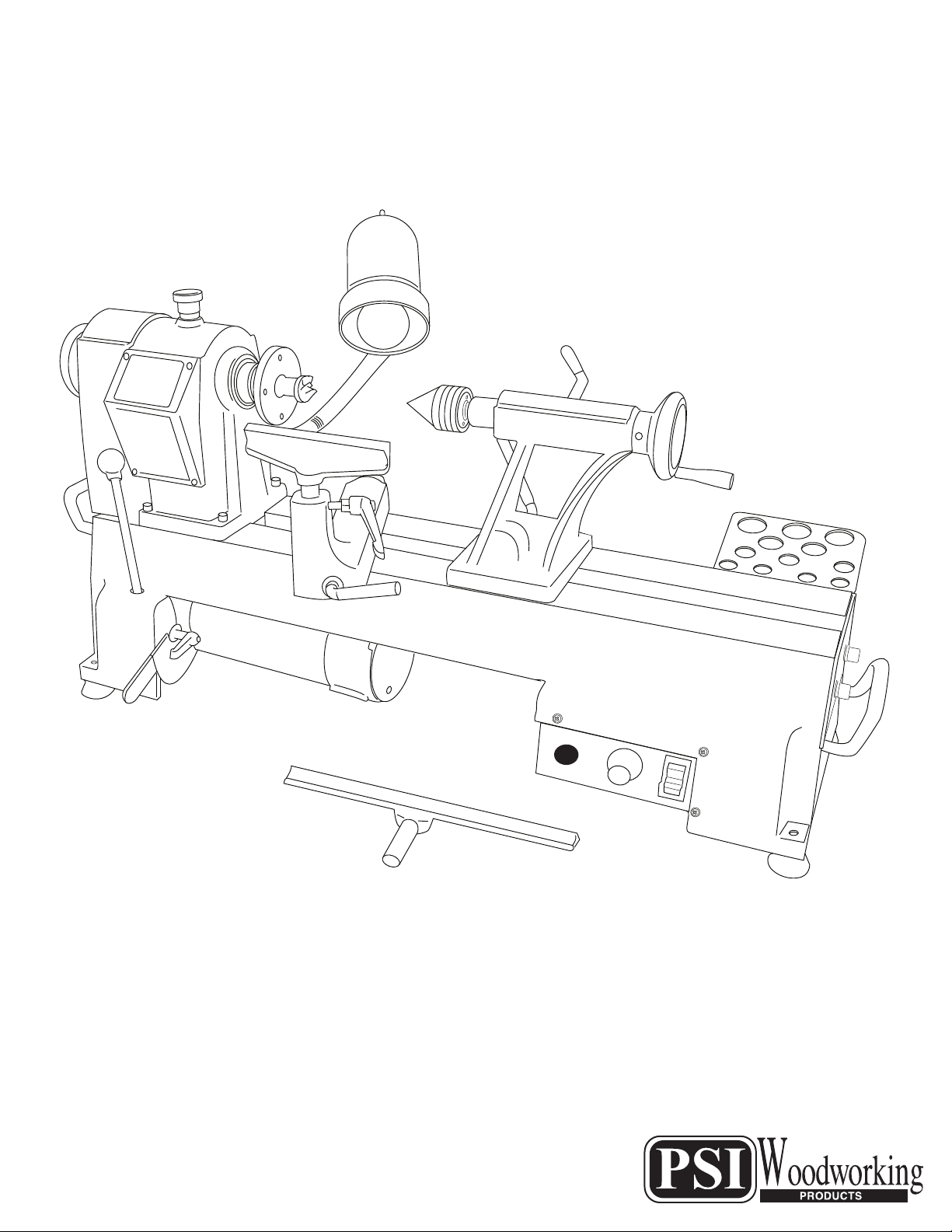
Turncrafter Commander Lathes User Manual
(Applies to models: TCLC10, TCLC10VS & TCLC12VS)
Read this manual completely before usage.
Model shown: TCLC12VS
www.psiwoodworkingproducts.com

2
SAFETY INSTRUCTIONS
1. Read and understand this instruction manual.
2. NEVER connect plug to power source until all the assembly steps have been completed.
3. Check that your supply voltage and grounding are correct.
4. Do not use the lathe in a damp or wet location.
5. Keep lathe clean and lightly oiled.
6. Make sure the belt, pulley, and control box are adequately guarded at all times.
7. Always remove tools, chuck keys, toggle bars, etc. When you are nished with them.
8. Keep the work area well lit and adequate ventilation in the workspace.
9. Keep young children and bystanders a safe distance from the lathe.
10. Do not force the lathe to do more than it is designed to do.
11. Do not wear loose clothing, jewelry or neckties, which could get caught in revolving parts. It is recommended that
long hair be restrained.
12. Safety eye wear should be worn at all times. Also, it is recommended to use a face or dust mask during lathe
operation.
13. Attach all work pieces securely to the lathe, whether between centers, on faceplates, or in chucks, etc.
14. For best results be sure to keep turning tools sharp, clean, and free from rust.
15. Use only three wire extension cords that have 3-prong grounding type plugs and 3-hole receptacles that except
the tool’s plug.
16. Check the speed BEFORE mounting any material onto the lathe. ALWAYS start the lathe at its slowest speed.
17. Always use an appropriate speed for the projects being turned - Slow speeds for larger bowls, faster speeds for
smaller spindles.
18. Keep the door to the pulleys and belts securely screwed closed during lathe operation.
19. Always check that the index/spindle lock knob is disengaged prior to turning on the lathe.
20. Vacuum excess dust build-up that may accumulate in or near the variable speed control box.
WARRANTY
The Turncrafter Commander Lathes are warranted against defects in materials and workmanship for a period of three
(3) years from the date of purchase. This warranty applies to the purchaser of this product, and is limited to repair or
replacement of the product or it’s parts at PSI Woodworking Products’ discretion. Excluded are parts, which have been
misused, abused, altered, or consumed by normal operation of the machine. Also excluded are direct or consequential
damages to the persons, property, and/or materials. Your invoice serves as proof of purchase and must be referenced
prior to return authorization.
Contact your dealer where you purchased your lathe for service or repair issues.
Date Purchased Invoice No.

3
Turncrafter Commander 10” Swing Multi Speed
Commander
10” Swing Variable Speed
Commander
12” Swing Variable Speed
Commander
Item No. #TCLC10 #TCLC10VS #TCLC12VS
Motor Speeds Single Speed 110v Variable Speed 110v Variable Speed 110v
Motor Power 3/5 HP 3/4 HP 1 HP
Belt Positions 5 2 2
Speeds 650, 1000,1450, 2000,
3000 RPM
Variable 150-1900 & 300-
3600 RPM
Variable 150-1900 & 300-
3600 RPM
Headstock Thread 1” x 8tpi 1” x 8tpi 1” x 8tpi
Between Centers 18” 18” 18”
Construction Cast Iron Cast Iron Cast Iron
Swing over bed 10” 10” 12”
Weight 83lbs. 82lbs. 106lbs.
Footprint 31” x 7-1/4” 31” x 7-1/4” 32” x 10”
Tailstock Travel 1-5/8” 1-5/8” 1.5/8”
Turncrafter Commander Specifications
SPECIFICATIONS OF TURNCRAFTER COMMANDER MIDI LATHES
Included with Lathe
Tool Rests(s) 6” tool rest 6” tool rest 6 &12” tool rests
Face Plate 4” faceplate 4” faceplate 4” faceplate
#2MT Spur Drive Center Included Included Included
Heavy Duty Tailstock Live
Center
Included Included Included
Carry Handles -- -- Included
4
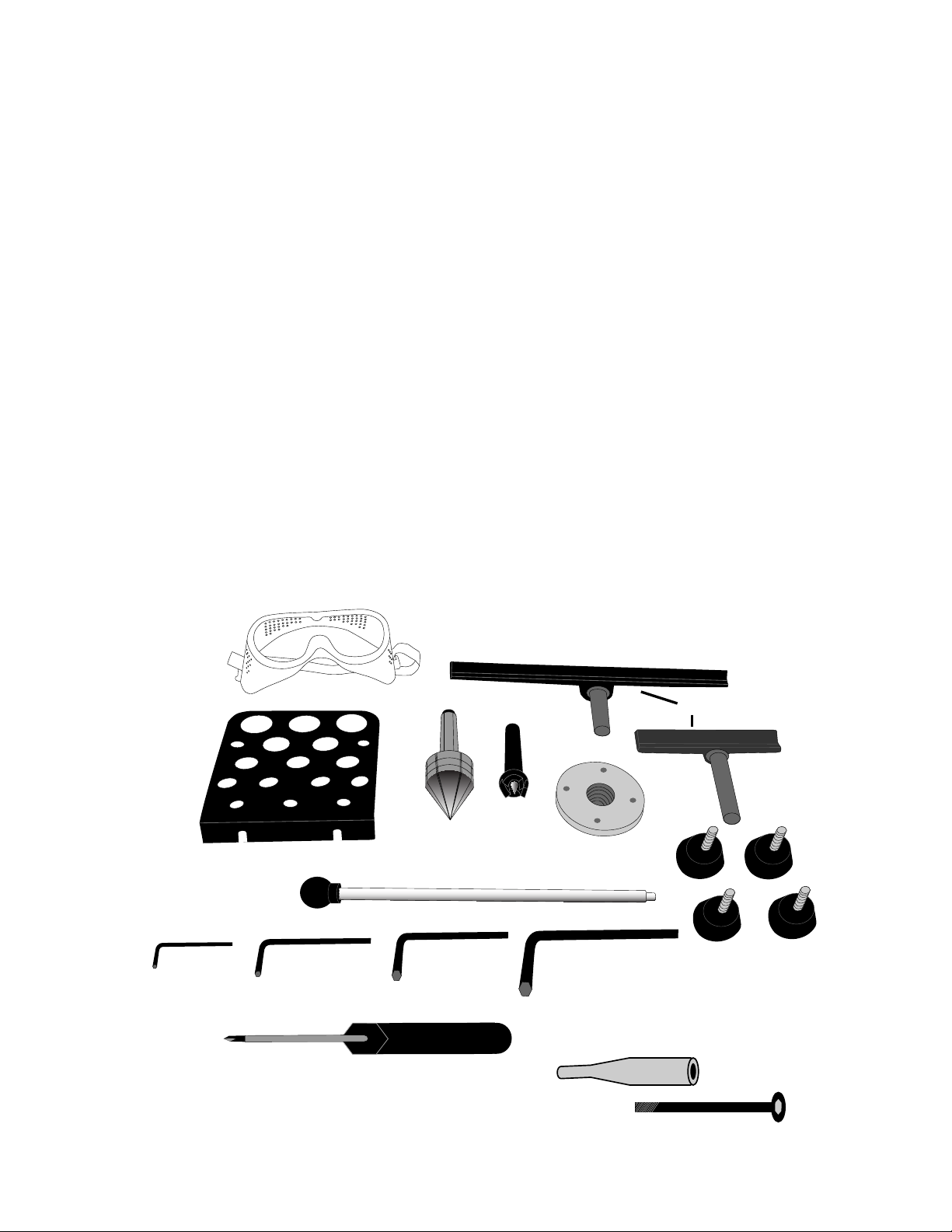
Receiving Loose Parts
A
B
C
D
E
F
G
H
J
IK
A. Tool rest (6in) and (10in) (Model TCLC12VS)
B. Faceplate (3in)
C. Spur Drive Center (#2 MT)
D. Hex wrench (set of 4)
E. Rubber feet (4) (if not installed)
F. Safety Goggles
G. Knock-out rod
H. Tool Caddy
I. Phillips Screw Driver
J. Live tailstock center
K. Tailstock Handle and bolt
RECEIVING:
1. Remove all parts and components from shipping carton. Remove all the packing and locate all loose parts.
2. Inspect the contents of the carton for shipping damage. Compare the contents of the loose parts list provided.
Report any missing or damaged parts to your distributor.
3. Keep the carton and packing material in case you need to pack and move the lathe.
4. Some metal surfaces on the lathe may have been treated with a protective coating prior to shipping. Clean
them with a soft rag prior to use. DO NOT use paint thinner, gasoline, or any other heavy solvents to remove
the protective coating or you will damage the lathe’s painted surface. Clean the lathe using only a damp cloth
or a very mild solvent.

5
LATHE COMPONENTS AND ASSEMBLY
1
2
3
4
5
6
7
8
9
10
11 12
13
13
14
15
16
17
18
19
20
21
22
23
24
25
26
6
10A
27
28
29
1. Lathe Bed
2. Tailstock
3. Hand Wheel (Quill Adjustment)
4. Quill Tightening Lever
5. Live Tailstock Center
6. 6” Tool rest (12” with TCLC12VS only)
7. Headstock
8. Faceplate
9. Headstock Hand Wheel
10. Motor & Adjustment lever (10A)
11. Speed Control (VS Models)
12. Power Switch
13. Spindle Lock Knob
14. Index Indicator
15. Cord Wrapping Supports
16. Tool Holder rack
17. Knockout Rod
18. Work Light (BULB NOT INCLUDED)
19. Mounting Holes for extension bed
20. Rubber Feet (4)
21. Variable Speed Indicator Window (VS Models)
22. Tailstock tightening lever
23. Tool rest holder Assembly
24. Spur Drive Center
25. Reset Button (VS models)
26. Carry Handles (VS Models)
27. Tool rest post tightening lever
28. Tool rest holder tightening lever
29. Belt Cover
Lathe Assembly Components

6
1. Install loose parts (a) - (k) as indicated in the assembly diagram above.
2. Inspect Tailstock: Verify that all knobs and handles work properly and that tailstock slide along bed and live center
bearings spin freely.
3. Tool rest: (6) - Verify all handles work properly and assembly (23) slides and locks properly along bed.
4. Headstock: (7) - Belt is attached and tight. Door levers and bearings operate properly - spindle turns freely.
5. Control Box: (11) - Check that knob and switch is intact and operate without power.
6. Spindle Lock: (13) - Make sure it engages and disengages and it properly locks spindle at indexing indicator. Unlock
knob before turning on lathe.
7. Turn Power: (12) - to off position. Plug in lathe. Test work light switch.
8. Dial speed to lowest speed. Make sure spindle turns freely and free from loose parts or obstructions. Turn on lathe.
Test speed knob (11) from slow to fast. (VS Models only)
GENERAL ASSEMBLY - INSTRUCTIONS
Mounting:
Before assembly, the lathe can be permanently attached to a work surface by inserting screws through the holes in the
base. Be sure to position the tool so that there is an open space directly beneath the motor to prevent shavings from
building up and fouling the motor fan housing. For general tabletop work (portable), install the (4) rubber feet (21)
Control Box:
Align the control box with the threaded holes on the tail stock side of the
lathe. Insert the two screws through the hinge plate and into the corre-
sponding holes on the lathe body.
Tool Caddy:
Using the two pan head screws, install the tool caddy on the rear of the lathe.
Control Box
Tool Caddy:
7
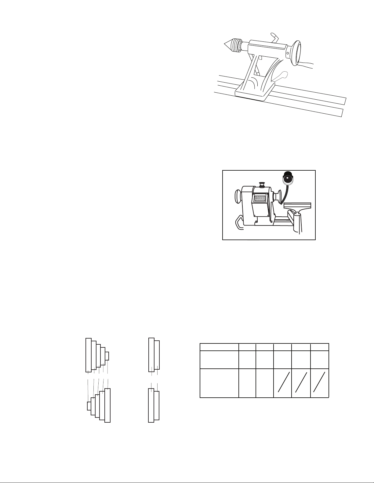
Pulley Positions and Speeds
TCLC10 Multi Speed
Spindle
Motor
a b c d e a b
TCLC10VS, TCLC12VS
Speeds RPM
TCLC10 650 1000 1400 2000 3000
TCLC10V 150- 300-
TCLC12V 1900 3600
Live Tailstock Center - Install and remove:
Turn the tailstock hand wheel (3) clockwise to extend the tail-
stock spindle. Turn it counter clockwise to retract the tailstock
spindle. The tailstock quill lock (4) locks the quill at its current
extension. Be sure to release the lock before attempting to
adjust the quillês extension. The tailstock lock (28) locks the
tailstock in its current position on the bed in relation to the
headstock. Release to move the tailstock assembly closer or
further from the headstock.
To adjust clamping to the bed, slide the tailstock off the bed
and rotate the nut located on the bottom of the tailstock.
Work Lamp:
Use only a 40 watt or smaller bulb in the work lamp.
Position the lamp to prevent shavings from accumu-
lating in the housing. Bulb not included. 3000
Live Tailstock Center
Work Lamp:
Remove the belt cover (29). Loosen motor racket handle (10).
Move belt to speed position as indicated in illustration below.
a b c d e

8
USE OF INDIVIDUAL COMPONENTS
Powering the Lathe:
The power switch (12) controls the ow of power to the motor. Toggling the switch to the ON position will start the mo-
tor. The lathe will begin turning and reach its full speed within a few seconds. The time the motor takes to reach its full
speed will depend on the size of the work piece and the speed setting. Toggle the switch to the OFF position to stop
the lathe. Wait for the tool to come to a complete stop before attempting any further operation.
(VS Models Only)
The speed control knob (11) determines the rate at which the lathe will turn. Turn the knob clockwise to increase
speed control and counter clockwise to decrease speed. Always set this to the lowest setting prior to turning on the
lathe. The lathe speed is indicated digitally through the window. (21)
Indexing Operation:
The indexing knob (13) allows you to make evenly spaced cuts on a work piece while keeping the headstock spindle
locked. The spindle index indicator (14) has 24 grooves so the turning’s sections can be made in multiples of 24, 12,
8, 6, 3, and 2. For example, to make 8 equal sections, mark your work at 1, 4, 7, 10, 13, 16, 19, and 22.
To use the index pin (13), screw it into the headstock until it engages a hole in the spindle pulley. Make your rst
indexing operation. Next, unscrew the index pin so that it frees the spindle, and rotate the next spindle position. Con-
tinue until all operations are completed.
Always back the index pin out completely before turning on the lathe.
1
1
2
2
3
3
4
5
6
7
8
4
5
6
7
8
9
10
11
12
13
14
15
16
17
18
19
20
21
22
23 24
Example of Indexing 8 equal sections
Spur Center (24) - The spur drive center locks into the headstock and
holds the work piece in place while the spindle is in operation. The knock-
out rod (g) slides into the headstock from the rear to tap the spur center
free. The knockout rod can be stored in the hole (17) in the front of the
lathe. When performing this operation, be sure to hold the spur center to
prevent it from falling and damaging the tip.
Warning - Be sure to clean both the taper on the spur center and the inside of the
headstock spindle prior to mounting the spur center. Failure to do so may cause the
two components to separate causing possible injury or damage to the tool.
Faceplate (8) - Note: The faceplate is pre-installed with your lathe.
Remove it prior to using the lathe. The faceplate screws directly on to
the headstock spindle. Use brass wood screws (not included) to secure your work piece to the face plate. Use
screws that are not overly long to ensure that they do not enter the portions of the work piece where you plan to
remove the material. To remove the faceplate from the spindle, lock the spindle with the index screw and unscrew
the faceplate.

9
RECOMMENDED TURNING SPEEDS
WARNING. Turning too fast for the size of your work may result in injuring yourself or damaging the lathe!
Work piece
Diameter
Max RPM
Roughing
Max RPM
Finishing
1” 3600 3600
2” 3000 4000
3” 2000 2600
4” 1500 2000
5” 1200 1600
6” 1000 1330
7” 850 1100
8” 750 1000
9” 660 900
10” 600 800
11” 540 725
12” 600 660
Maximum Speeds for Balanced Turnings
Multi Speed Chart for TCLC10
Max work
piece dia.
Max Speed
Roughing
9”
Finishing
10”
610
6” 8” 1000
4” 5.5” 1450
3” 4” 2000
2” or less 2.5” 3000
Chart for TCLC10VS & TCLC12VS
Tool Rest (6) - The tool rest is used to steady the cutting tool while the lathe is in operation. You can position the tool
rest by releasing the lock handle(28) positioned on the side of the rest and sliding the rest into the desired position.
Tighten the lock handle to secure the tool rest into position. The height of the tool rest can be adjusted releasing the
lock handle(27) located on the front of the rest and adjusting the height to the desired position and then tightening the
lock handle.
The position of the entire tool rest can be adjusted by reaching under the bed and loosening the clamp nut. Slide
the rest into position. Tighten the clamp nut. The tool rest should be positioned just above the center line of the work
piece.
Note: The lock levers are spring loaded. To operate, pull out on the lever, rotate it on the pin, and then release.
Changing Belt Speeds - Make sure the lathe is unplugged. Loosen the knob on the cover plate. Slide the cover up
and off the lathe. Loosen the motor plate ratchet handle (10) to allow the motor plate to swivel upwards. To change the
speed, move the belt drive from one pulley to another. (Note, Always go from the larger pulley to the smaller pulley)
After moving the belt, tighten the motor pulley with the ratchet handle (10)- this also tightens the belt. Turn your latheês
power on, and make sure that the belt is running consistently in its parallel groove (this should be done with the hand
wheel(9). If all is smooth, turn the power off, reattach the cover.
Replacing the Belt -
The Turncrafter Commanders are designed with a special feature that allows quick and easy belt changes.
• Loosen belt, `Remove old belt
• Slide the new belt over the headstock spindle pulley and onto the motor pulley.

10
TYPICAL LATHE OPERATIONS
Spindle Turning
• Work mounted between headstock spur center and live tailstock center
• Requirements: no additional accessories
• Optional headstock mounting with lathe chuck
Bowl Turning
• Mount work to faceplate with screws
• Requirements: no additional accessories
• Lathe chuck optional
Pen Making
• Work mounts on pen mandrel - secured between centers
• Requirements: pen mandrel
Drilling
• Work mounted on headstock
• #2MT drill chuck mounted in tailstock
• Requirements: lathe chuck, #2MT drill chuck
Sanding
Use the fastest speed possible without burning the wood. Use graduated grits from 150 grit for best results.
Finishing
Generally nishing can be done at faster speeds than turning. Finish using nishing polishes, waxes and bufng com-
pounds on or off the lathe.

11
Accessories Available From Psi Woodworking Products
For Your Commander Lathe
Item Description Typical Products
Lathe Extension Bed Extends the lathe and Spindle you can turn to 42” #TCLC10XB for 10” Styles
#TCLC12XB for 12” Style
Duplicating Attach-
ment
Enables duplicating small projects to 9” long.
Makes fast and easy copies.
#CMLDUPJ for 10” Styles
#CMLDUPR for 12” Style
Chucks To mount up a variety of work on to your head-
stock. Styles include drill chucks, mini chucks,
screw chucks, collet chucks and chuck styles for
larger work.
#CSC3000C Versatile self cen-
tering multi component system.
Plus many other styles avail-
able.
Pen Mandrels Essential for making pens and other small projects
on your lathe. Mounts pen blanks for turning and
nishing.
#PKM-FLC - Fits into the #MT2
opening in the headstock
Lathe Tools Skew Chisels - for nal nishing and smooth cuts
and beading
Parting Tools - to trim off waste establish a diameter
or cut at areas
Roughing Gouges- For aggressively taking square
spindles to a round
Spindle Gouges - For general purpose turning a
spindle from rough round to a near nish. A favor-
ite for pens.
Scrapers - For smoothing and for interior clean up
inside a bowl after gouge work is completed.
Bowl Gouges - Used for hollowing out bowl centers.
Used on most faceplate work.
Lathe Tool sets - Include a variety of sizes and styles
of the above.
Specialty Tools for: Making beads and coves, in-
terior and exterior bowl nishing, bowl hollowing,
making Tenons and Dovetails and more.
#LX10 1/2” plus others
#LX410 1/2” plus others
#LX260 1” plus others
#LX320 3/8” plus others
#LX120 1” plus others
#LX210 3/8” plus others
#LCHSS8 - 8 pc variety
Other specialty sets available
#LCHOLSET - Bowl hollowing
set with replaceable cutters and
others
Faceplates For Mounting bowls. Many sizes are available de-
pending on the size of the bowl being turned.
#CF6 - 6” faceplate many other
sizes available
Drive Centers Many styles available for special applications #LCENTSS21 - Super drive
multi prong style plus others
Toolrests Many special proles available for bowl turning,
longer work, shorter work.
#CLTSJ - “S” toolrest for bowl
turning plus others
Other Equiptment Specialty items to use with your lathe include: sanding systems, special chuck jaws,
measuring and marking products, tailstock centers and more.
For more information visit www.psiwoodworking.com

12
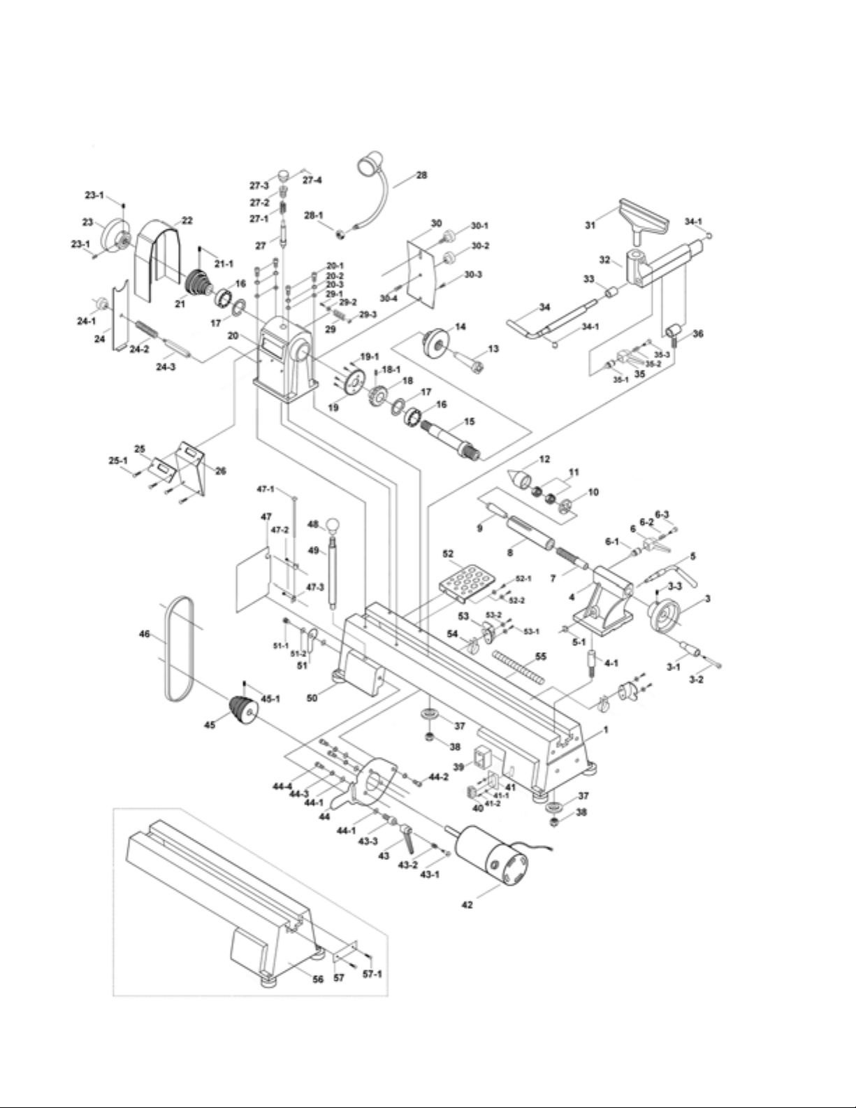
10” & 12” Variable Speed Models
TCLC10VS and TCLC12VS Part List

13
1 Bed 1
2 Hex socket screw M10x25 2
2-1 Washer Ø10 2
3 Handle 2
3-1 Retaining ring 10 2
4 Quill adjusting wheel 1
4-1 Bush 1
4-2 Screw 1
5 Tailstock 1
5-1 Cam follower tailstock 1
6 Handle 1
6-1 Lock bolt 1
6-2 Spring 1
6-3 Bolt 1
7 Eccentric axis 1
7-1 Retaining ring 10 1
8 Tailstock quill 1
9 Tailstock axis 1
10 Taper rod 1
11 Ball bearing 1
12 Ball bearing 2
13 Cup center 1
14 Headstock spur center 1
15 Face plate 1
16 Headstock spindle 1
17 Ball bearing 80105 2
18 Retaining ring 47 2
19 Gear 1
19-1 Hex socket screw M6x12 1
20 Round plate 1
20-1 Semi-circle head screw M4x8 4
21 Headstock 1
21-1 Hex socket screw M8x30 4
21-2 Spring washer 4
33 Work light 1
33-1 Hex nut M12 1
34 Tool rest 6” 1
34-1 Tool rest 12”
35 Tool rest base 1
36 Bush 1
37 Lock handle for tool rest base 1
37-1 Retaining ring 10 2
38 Handle 1
38-1 Lock bolt 1
38-2 Spring 1
38-3 Bolt 1
39 Tool rest cam follower 1
40 Lock nut 2
41 Nut M10 2
42 Switch-box 1
42-1 strain relief 2
42-2 strain relief 2
42-3 Switch 1
42-4 Semi-circle head screw M4x20 3
42-5 Hex nut M4 1
43 Variable plate 1
43-1 Tapping screw 4
44 Switch-box plate 1
44-1 Tapping screw 4
45 Motor 1
46 Handle 1
46-1 Lock bolt 1
46-2 Spring 1
46-3 Bolt 1
1-3 Washer Ø8 4
22 Drive pulley 1
22-1 Hex socket taper screw M6x12 1
23 Side protection guard 1
24 Hand wheel 1
24-1 Hex socket screw M6x12 2
25 Side plate 1
25-1 Stationary knob 1
25-2 Spring 1
25-3 Connecting rod 1
26 Connecting plate 1
26-1 Semi-circle head screw M3x12 2
26-2 Washer 2
26-3 Hex nut M3 2
27 Display plate 1
27-1 Tapping screw 4
27-2 Connector 1
28 Front protection guard 1
29 Cover 1
29-1 Semi-circle head screw M4x12 4
30 Rear plate 1
30-1 Moving knob 1
30-2 Stationary knob 1
30-3 Screw 1
30-4 Screw 1
31 Connecting stand 1
31-1 Semi-circle head screw M3x12 1
31-2 Washer Ø3 1
31-3 Hex nut M3 1
32 Stop bolt 1
32-1 Spring 1
32-2 Bush 1
32-3 Cap 1
32-4 Screw 1
47 Motor plate with notch 1
47-1 Washer Ø6 1
47-2 Hex socket screw M8x16 1
47-3 Spring washer 3
47-4 Hex socket screw M6x16 3
48 Motor pulley 1
48-1 Hex socket screw M6x12 1
49 Drive belt 1
50 Rubber washer 6
51 Door latch 1
51-1 Washer 2
51-2 Screw 1
52 Mounting plate 1
52-1 Pin hinge 1
52-2 Hinge 2
52-3 Semi-circle head screw M4x8 2
53 Ball 1
54 Knock-out rod 1
55 Tool rack 1
55-1 Semi-circle head screw M5°¡12 2
55-2 Washer Ø5 2
56 Support 2
56-1 Semi-circle head screw M5x12 4
56-2 Washer Ø5 4
57 Wire hanger 2
58 Tube 1
59 Extension bed 1
60 Small plate 1
60-1 Semi-circle head screw M5x8 2
Part No. Description QTY Part No. Description QTY
14
TCLC10 Part List

15
1 Bed 1
3 Quill adjusting wheel 1
3-1 Bush 1
3-2 Screw 1
3-3 Hex socket screw M6x12 1
4 Tailstock 1
4-1 Cam follower tailstock 1
5 Eccentric axis 1
5-1 Retaining ring 10 1
6 Handle 1
6-1 Lock bolt 1
6-2 Spring 1
6-3 Bolt 1
7 Tailstock quill 1
8 Tailstock axis 1
9 Taper rod 1
10 Ball bearing 1
11 Ball bearing 2
12 Cup center 1
13 Headstock spur center 1
14 Face plate 1
15 Headstock spindle 1
16 Ball bearing 80105 2
17 Retaining ring 47 2
18 Gear 1
18-1 Hex socket screw M6x12 1
19 Round plate 1
19-1 Semi-circle head screw M4x8 4
20 Headstock 1
20-1 Hex socket screw M8x30 4
20-2 Spring washer 4
20-3 Washer Ø8 4
21 Drive pulley 1
21-1 Hex socket taper screw M6x12 1
22 Side protection guard 1
23 Hand wheel 1
23-1 Hex socket screw M6x12 2
24 Side plate 1
24-1 Stationary knob 1
24-2 Spring 1
24-3 Connecting rod 1
25 Cover 1
25-1 Semi-circle head screw M4x12 4
26 Front protection guard 1
27 Stop bolt 1
27-1 Spring 1
27-2 Bush 1
27-3 Cap 1
27-4 Screw 1
28 Work light 1
28-1 Hex nut M12 1
29 Connecting stand 1
29-1 Semi-circle head screw M3x12 1
29-2 Washer 1
29-3 Hex nut 1
30 Rear plate 1
30-1 Moving knob 1
30-2 Stationary knob 1
30-3 Lock screw 1
30-4 Screw 1
31 Toolrest 1
32 Toolrest base 1
33 Bush 1
34 Lock handle for tool rest base 1
34-1 Retaining ring 10 2
35 Handle 1
35-1 Lock bolt 1
35-2 Spring 1
35-3 Bolt 1
36 Tool rest cam follower 1
37 Lock nut 2
38 Nut M10 2
39 Switch box 1
40 Switch 1
41 Switch-box plate 1
41-1 Washer Ø4 2
41-2 Semi-circle head screw M4x25 2
42 Motor 1
43 Handle 1
43-1 Bolt 1
43-2 Spring 1
43-3 Lock Bolt 1
44 Motor plate with notch 1
44-1 Washer Ø6 4
44-2 Hex socket screw M8x16 1
44-3 Spring washer 3
44-4 Hex socket screw M6x16 3
45 Motor pulley 1
45-1 Hex socket screw M6x12 1
46 Drive belt 1
47 Mounting plate 1
47-1 Pin hinge 1
47-2 Semi-circle head screw M4x8 2
47-3 Hinge 2
48 Ball 1
49 Knock-out rod 1
50 Rubber washer 6
51 Door latch 1
51-1 Screw 1
51-2 Washer 1
52 Tool rack 1
52-1 Semi-circle head screw M5x12 2
52-2 Washer Ø5 2
53 Support 2
53-1 Semi-circle head screw M5x12 4
53-2 Washer Ø5 4
54 Wire hanger 2
55 Tube 1
56 Extension bed 1
57 Small plate 1
57-1 Semi-circle head screw M5x8 2
Part No. Description QTY Part No. Description QTY
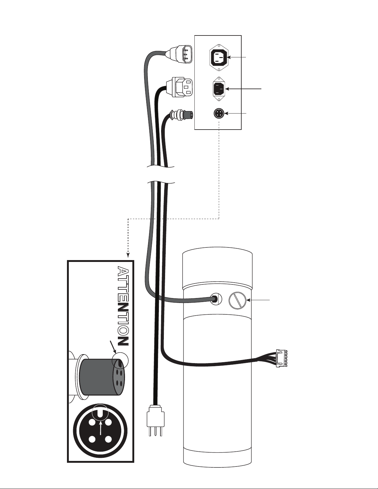
To make connection to the control box
1. Pre-attached - wire from the motor to the box (A) CAUTION: DO NOT PLUG A into B
2. Plug FEMALE end of the power cord into control box. (B)
3. Pre-attached - Plug in cord from the headstock. (C)
4. Plug MALE end of power cord into 110v power outlet.
Motor connection
motor to control box
(pre-attached)
Power connection
Speed input
motor to headstock
(pre-attached)
TCLC10VS Motor Connections
Speed input
motor to headstock
(pre-attached)
Power cord
motor to outlet
AB
C
A
B
C
Brush cap
ATTENTION
Notch on plug
and socket must
be align, for
proper operation.

ASSEMBLY OF TCLC12VS VARIABLE SPEED LATHE
second contains the headstock assembly, toolrest and tailstock assembly.
The parts shown below:
*incates that item is in Box 1
to the positon you wish to use. See User’s Manual for speed choice. Then screw on handwheel to headstock
stock assembly. Make sure that all connections are tight and secure. Lastly attach the lead wire plug from the
motor to the headstock socket (over for motor connections ). Now you are ready to turn on your lathe.
Maximum Speed For
Balanced Turnings
Maximum RPM
Roughing
Maximum RPM
Finishing
Workpeice Diameter
1”
2”
3”
4”
5”
6”
7”
8”
9”
10”
11”
12”
4100 4100
4000
3000
2000
2000
2600
1500
1200 1600
1000 1330
850 1100
750 1000
660
660
900
600 800
540
500
725
HEAD STOCK SPINDLE SPEED
ON
OFF
DC Motor
Headstock Assembly
Tailstock Assembly
Toolrest(s)*
Lathe Bed
Belt Cover
Handwheel*
Belt Contents of Box 2
Contents of Box 1
A
A
Indexing Knob*
*
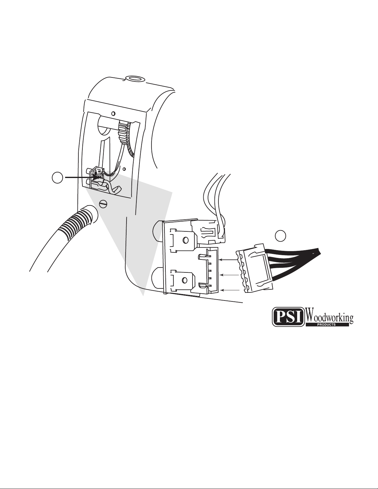
Connecting the Motor to the Board
Lead from Motor
Connection in Headstck
A
A
TCLC12VS Assembly - 10/10 v2

©2010 PSI Woodworking Products
V.510
This manual suits for next models
2
Table of contents
Other PSI Woodworking Products Lathe manuals


