PSI Woodworking Turncrafter Tailspinner TCLT10VS User manual

© 2013 PSI Woodworking • Philadelphia, PA 19115 v5/13
Turncrafter Tailspinner
™
Lathe
User’s Manual for models
TCLT10VS (10” swing) and TCLT12VS (12” swing)
V1
Distributed by: © 2022 PSI Woodworking • Philadelphia, PA 19115
Manufactured by: Penn State Industries • Philadelphia, PA 19115 Manual #TCLTMAN
Featuring the live Tailstock
Patent Pending

TCLT10VS TCLT12VS PSI Woodworking Products
Distributed by: © 2022 PSI Woodworking • Philadelphia, PA 19115
Manufactured by: Penn State Industries
2
1. KEEP GUARDS IN PLACE and in working order.
2. KEEP WORK AREA CLEAN. Cluttered areas and benches invite
accidents.
3. DON’T USE IN DANGEROUS ENVIRONMENT. Don’t use power
tools in damp or wet locations, or expose them to rain. Keep work
area well lighted.
4. KEEP CHILDREN AWAY. All visitors should be kept safe distance
from work area.
5. MAKE WORKSHOP KID PROOF removing starter keys.
6. DON’T FORCE TOOL. It will do the job better and safer at the rate
for which it was designed.
7. USE RIGHT TOOL. Don’t force tool or attachment to do a job for
which it was not designed.
8. USE PROPER EXTENSION CORD. Make sure your extension cord
is in good condition. When using an extension cord, be sure to use
one heavy enough to carry the current your product will draw. An
undersized cord will cause a drop in line voltage resulting in loss of
power and overheating. Table shows the correct size to use
depending on cord length and nameplate ampere rating. If in doubt,
use the next heavier gage. The smaller the gage number, the
heavier the cord.
SPECIFIC SAFETY RULES FOR WOOD LATHES
WARNING - No adjustment should be made until the tool has been
stopped.
WARNING - Risk of injury due to accidental starting. Do not use in an
area where children may be present.
WARNING For Your Own Safety Read Instruction Manual Before
Operating Lathe.
a) Wear eye protection.
b) Do not wear gloves, necktie, or loose clothing.
c) Tighten all locks before operating.
d) Rotate workpiece by hand before applying power.
e) Rough out workpiece before installing on faceplate.
f) Do not mount split workpiece or one containing knot.
g) Use lowest speed when starting new workpiece.
WARNING: DO NOT EXPOSE TO RAIN OR USE IN DAMP
LOCATIONS.
ADDITIONAL SAFETY RULES FOR WOOD LATHES
1. Do not allow the turning tools to bite into the wood. The wood could
split or be thrown from the lathe.
2. Always position the tool rest above the center line of the lathe when
shaping a piece of stock.
3. Do not operate the lathe if it is rotating in the wrong direction. The
workpiece must always be rotating toward you.
4. Before attaching a workpiece to the faceplate, always rough it out to
make it as round as possible, this minimizes the vibrations while the
piece is being turned. Always fasten the workpiece securely to the
faceplate, failure to do this could result in the workpiece being
thrown away from the lathe.
5. Position your hands so that they will not slip onto the workpiece.
9. WEAR PROPER APPAREL. Do not wear loose clothing, gloves,
neckties, rings, bracelets, or other jewelry which may get caught in
moving parts. Nonslip footwear is recommended. Wear protective
hair covering to contain long hair.
10. ALWAYS USE SAFETY GLASSES. Also use face or dust mask if
cutting operation is dusty. Everyday eyeglasses only have impact
resistant lenses, they are NOT safety glasses.
11. DON’T OVERREACH. Keep proper footing and balance at all
times.
12. MAINTAIN TOOLS WITH CARE. Keep tools sharp and clean for
best and safest performance. Follow instructions for lubricating and
changing accessories.
13. DISCONNECT TOOLS before servicing; when changing
accessories, such as blades, bits, cutters, and the like.
14. REDUCE THE RISK OF UNINTENTIONAL STARTING. Make sure
switch is in off position before plugging in.
15. USE RECOMMENDED ACCESSORIES. Consult the owner’s
manual for recommended accessories. The use of improper
accessories may cause risk of injury to persons.
16. NEVER STAND ON TOOL. Serious injury could occur if the tool is
tipped or if the cutting tool is unintentionally contacted.
17. CHECK DAMAGED PARTS. Before further use of the tool, a guard
or other part that is damaged should be carefully checked to
determine that it will operate properly and perform its intended
function – check for alignment of moving parts, binding of moving
parts, breakage of parts, mounting, and any other conditions that
may affect its operation. A guard or other part that is damaged
should be properly repaired or replaced.
18. NEVER LEAVE TOOL RUNNING UNATTENDED. TURN POWER
OFF. Don’t leave tool until it comes to a complete stop.
GENERAL & SPECIFIC
SAFETY RULES
2
GENERAL AND SPECIFIC SAFETY RULES FOR
WOODWORKING MACHINES
h)
i)
j)
k)
l)
Volts Total length of cord in feet
120 V 25 ft 50 ft 100 ft 150 ft
More than Not More than AWG
0 6 18 16 16 14
Ampre Rating
Volts Total length of cord in feet
120 V 25 ft 50 ft 100 ft 150 ft
More than Not More than AWG
6 10 18 16 16 14
10 12 16 16 14 12
12 16 14 12 Not Reccomended
Ampre Rating

Distributed by: © 2022 PSI Woodworking • Philadelphia, PA 19115
Manufactured by: Penn State Industries
TCLT10VS TCLT12VS PSI Woodworking Products
3
SPECIFICATIONS OF THE TURNCRAFTER TAILSPINNER MIDI LATHE
Turncrafter Commander
Specication
10” Swing Tailspinner 12” Swing Tailspinner
Item No. #TCLT10VS #TCLT12VS
Motor Speeds Variable Speed 110v Variable Speed 110v
Motor Power 1 HP-7A 1.5 HP-11A
Belt Positions 2 2
Speeds Variable 450-1700 RPM &
950-3800 RPM
Variable 450-1600 RPM &
950-3600 RPM
Headstock/Live Tailstock 1” x 8tpi / #2 MT 1” x 8tpi / #2 MT
Between Centers max 14.5” max 14.5”
Construction Cast Iron Cast Iron
Swing over bed 10” 12”
Weight 82 lbs. 106 lbs.
Footprint 31” x 7-1/4” 31” x 9-1/2”
Tailstock Travel 4” 4”
WARRANTY
Turncrafter Commander Lathes are warranted against defects in materials and workmanship for a period of three (3) years
from the date of purchase. This warranty applies to the purchaser of this product, and is limited to repair or replacement of the
product or its parts at PSI Woodworking Products discretion. Excluded are parts which have been misused, abused, altered,
or consumed by normal operation of the machine. Also excluded are direct or consequential damages to the persons, prop-
erty, and/or materials. Your invoice serves as proof of purchase and must be referenced prior to return authorization. Contact
your dealer where you purchased your lathe for service or repair issues.

TCLT10VS TCLT12VS PSI Woodworking Products
Distributed by: © 2022 PSI Woodworking • Philadelphia, PA 19115
Manufactured by: Penn State Industries
4
RECEIVING
1. Remove all parts and components from shipping carton. Remove all the packing and locate all loose parts.
2. Inspect the contents of the carton for shipping damage. Compare the contents of the loose parts to the list
provided. Report any missing or damaged parts to your distributor.
3. Keep the carton and packing material in case you need to pack and move the lathe.
4. Some metal surfaces on the lathe may have been treated with a protective coating prior to shipping.
Clean them with a soft rag prior to use. DO NOT use paint thinner, gasoline, or any other heavy solvents
to remove the protective coating or you will damage the lathe’s painted surface. Clean the lathe using only
a damp cloth or a very mild solvent.
A. Tool rest (6”) and (12”)
B. Faceplate (3” pre-installed)
C. (2 ea) Spur Drive Centers (#2 MT)
D. Hex wrench (set of 4)
E. Rubber feet (4) (if not installed)
F. Safety Goggles
G. Knock out rod
H. Tool Caddy
I. Phillips Screw Driver
J. Heavy duty tailstock
Dead Center
K. Tailstock Handle and bolt
L. Dead Mandrel Saver
M. Dead Safety Center
LATHE COMPONENTS
Loose Parts Included with Lathe (Box no.2 for #TCLT12VS)
D
ML
C
J
H
E
F
I
K
B
A
A

Distributed by: © 2022 PSI Woodworking • Philadelphia, PA 19115
Manufactured by: Penn State Industries
TCLT10VS TCLT12VS PSI Woodworking Products
5
1
23
4
5
6A
7
9
10
11
12
13
14
8
15
16
17
18
19
20
21
22
30
23
24
25
26
6B
10A
27
28 34
29
32
31
33
LATHE COMPONENTS
b
1. Lathe Bed
2. Live Tailstock Assembly (Patent Pending)
3. Hand Wheel (Quill Adjustment)
4. Quill Tightening Lever
5.Head Tailstock Center
6a. 6” Toolrest
6b. 12” Toolrest
7. Headstock
8. Faceplate (Installed for shipping)
9. Headstock Hand Wheel
10. Motor & Adjustment lever (10A)
11. Speed Control
12. Power Switch
13. Spindle Lock Knob & pin
14. Index Indicator
15. Cord Wrapping Supports (Not shown)
16. Tool Caddy
17. Knockout Rod
18. Work Light (40watt BULB INCLUDED)
19. Mounting Holes for extension bed
20. Rubber Feet (4)
21. Variable Speed Indicator Window
22. Tailstock tightening lever
23. Tool rest holder Assembly
24. (2) Spur Drive Centers
25. Reset Button
26. Carry Handles
27. Tool rest post tightening lever
28. Tool rest holder tightening lever
29. Belt Cover
30. Tailstock lock handle
31. Dead Mandrel Saver
32. Dead Safety Center
33. Tailstock Bearing Assembly
34. Tailstock spindle lock

TCLT10VS TCLT12VS PSI Woodworking Products
Distributed by: © 2022 PSI Woodworking • Philadelphia, PA 19115
Manufactured by: Penn State Industries
6
MOTOR CONNECTION (Both Models)
Motor connection
motor to control box
Power connection
Speed input
motor to headstock
Speed input
motor to headstock
Power cord
motor to outlet
AB
C
A
B
C
Brush cap
To mak e connec tion to the control bo x
1. Plug the wire from the motor to the box (A) CAUTION: DO NOT PLUG A into B
2. Plug power cord into control box. (B) CAUTION: DO NOT PLUG INTO OUTLET.
3. Plug in cord from switch box to headstock (C)
4. Plug power cord into outlet.(B) ATTENTION
Notch on plug
and socket must
be align, for
C
Control Box
The packing of the TCLT12VS is in two boxes. The rst box contains the lathe bed with motor assembly and switch box
(mounted). The second box contains the headstock assembly, toolrest and tailstock assembly.
NOTE: TCLT10VS is delivered in one box
Lead the digital readout
cable (C) from the switch box,
through the lathe bed and
attach to circuit board inside
the bottom of the headstock.
Please note your lathe is deliv-
ered with the motor cable (A)
and power cord (B) already
plugged into control box.
The packing of the TCLT12VS is in two boxes.
The rst box contains the lathe bed with motor
assembly and switch box (mounted). The second
box contains the headstock assembly, toolrest
and tailstock assembly.
NOTE: TCLT10VS is delivered in one box
The rst thing to install is the door closer bolt.
You will need the Knob and Closer Bolt (51, 51-
2), Washer(51-3), Spring (51-1), and Nut (51-4).
Items should come in a single parts pack. This
is best assembled with no belt installed and the
handle pulled out so there is easy access to the
inside of pulley area of the bed.
Insert Closer Bolt into hole next to the door.
Coming through the top opening, slide spring
over the part of the Bolt insode the Bed. Com-
press the Spring against the inside wall so the
Bolt threads are exposed. Using second hand,
through the side opening slide washer and thread nut onto the Bolt until it is rmly attached and release
the spring. Bolt knob will now stay against door to keep it closed and can be pulled back to open door for pulley access.
Attach headstock using the four screws and washers.
Install Belt (49, see page 8). Install Belt Cover (23) over the Pulley. Attach Side Plate (25) against Belt Cover with screws
and washers.
MaximumSpeed For
BalancedTurnings
MaximumRPM
Roughing
MaximumRPM
Finishing
r
e
t
e
m
a
iDec
i
ep
k
roW
1”
2”
3”
4”
”5
6”
”
7
”
8
”9
10”
11”
12”
4100 4100
4000
3000
2000
2000
2600
1500
1200 1600
1000 1330
850 1100
750 1000
660
660
900
600 800
540
500
725
HEAD STOCK SPINDLE SPEED
ON
OFF
DC Motor
Headstock Assembly
Tailstock Assembly
Toolrest(s)
Lathe Bed
Belt Cover
Handwheel
Belt Contents of Box 2
Contents of Box 1
Indexing Knob
Knob and
Closer Bolt (51, 51-2)
Spring (51-1)
ASSEMBLY

Distributed by: © 2022 PSI Woodworking • Philadelphia, PA 19115
Manufactured by: Penn State Industries
TCLT10VS TCLT12VS PSI Woodworking Products
7
Mounting Lathe to worksurface:
The lathe can be permanently attached to a work surface
by inserting screws through the holes in the base instead of
rubber feet. Be sure to position the lathe so that there is an
open space directly beneath the motor and work surface to
prevent shavings from building up and fouling the motor or
switch box (about the thickness of rubber feet between lathe
bed feet and work surface). For general tabletop work, install
the four rubber feet (20).
Install Tool Caddy: (16)
Using the two pan head screws, install the tool caddy on the
rear of the lathe bed.
Work Lamp: (18)
Use only a 40 watt or smaller bulb in the work lamp. Position
the lamp to prevent shavings from accumulating in the hous-
ing. Bulb not included.
Lock Pin: (13)
IMPORTANT - When NOT using the indexing feature, Pull up
the pin and rotate it to the UNLOCK position and drop it in place.
Check the lathe’s spindle to make sure it is spinning freely. The
pin MUST BE UNLOCKED with the spindle spinning freely before
turning on your Lathe – neglecting to do this may damage your
lathe when you next turn it on. See page 9 for indexing feature.
1. Install loose parts as indicated in the Assembly Diagram on pg.5.
2. Inspect Tailstock (2): Verify that all knobs and handles work properly and that the tailstock slides
along bed and live center bearings spin freely and locks with lock knobs
3. Tool rest: (6) - Verify all handles work properly and assembly (23) slides and locks properly along bed.
4. Headstock: (7) - Belt is attached and tight. Door levers and bearings operate properly and
spindle turns freely.
5. Control Box: (11) - Check that the knob and switch are intact and operate without power.
6. Indexing Spindle Lock: (13) - Make sure it engages and disengages and it properly locks spindle at
indexing indicator.
IMPORTANT - When NOT using the indexing feature, Pull up the pin and rotate it to the UNLOCK position and drop it in place. Check the
lathe’s spindle to make sure it is spinning freely. The pin MUST BE UNLOCKED with the spindle spinning freely before turning on your Lathe –
neglecting to do this may damage your lathe when you next turn it on.Unlock knob before turning on lathe.
7. Turn Power switch (12) - to off position. Plug in lathe. Test work light switch. (with power
switch in off position)
8. Dial speed to lowest speed. Make sure spindle turns freely and does not interfere with loose parts or
obstructions. Turn on lathe. Test speed knob (11) from slow to fast.
INSTRUCTIONS Prior to use
Tool Rest & Tailstock Assembly:
From the opposite end of the lathe bed, attach the toolrest (23) rst, then follow with the tailstock assembly (2).
Make sure all connections are tight and secure.
e
3000
Tool Caddy
Work Lamp:
Lock Pin
e
3000

TCLT10VS TCLT12VS PSI Woodworking Products
Distributed by: © 2022 PSI Woodworking • Philadelphia, PA 19115
Manufactured by: Penn State Industries
8
TCLT10VS TCLT12VS
Position A B A B
Minimum 450 950 450 950
Maxium 1700 3800 1600 3600
Speeds RPM*
A B
Spindle
Motor
USING YOUR LATHE
Powering the Lathe:
The power switch (12) controls the ow of power to the motor. Toggling the switch to the ON position will start the motor. The lathe will begin
turning and reach its full speed within a few seconds. The time the motor takes to reach its full speed will depend on the size of the work
piece and the speed setting. Toggle the switch to the OFF position to stop the lathe. Wait for the tool to come to a complete stop before at-
tempting any further operation.
Variable Speeds
The speed control knob (11) determines the rate at which the lathe will turn. Turn the knob clockwise to increase speed control and counter
clockwise to decrease speed. Always set this to the lowest setting prior to turning on the lathe. The lathe speed is indicated digitally through
the window. (21)
Changing Belt Speeds - Make sure the lathe is unplugged. Loosen the knob on the cover plate. Slide the cover up and off the lathe.
Loosen the motor plate ratchet handle (10a) to allow the motor plate to swivel upwards. To change the speed, move the belt drive from one
pulley to another. (Note, Always go from the headstock pulley to the motor pulley) After moving the belt, tighten the motor pulley with the
ratchet handle (10a); this also tightens the belt. Turn your lathe’s power on, and make sure that the belt is running consistently in its parallel
groove. If all is smooth, turn the power off, reattach the cover.
Work piece
Diameter
Max RPM
Roughing
Max RPM
Finishing
1” MAX MAX
2” 3000 MAX
3” 2000 2600
4” 1500 2000
5” 1200 1600
6” 1000 1330
7” 850 1100
8” 750 1000
9” 660 900
10” 600 800
11” 540 735
12” 600 660
Maximum Speeds for Balanced Turning
MAX = Maximum Lathe Speed 3600
Replacing the Belt
The Turncrafter Commanders are designed with a special
feature that allows quick and easy belt changes.
• Remove belt cover
• Loosen motor plate handle (10a)
• Loosen belt and remove old belt
• Slide the new belt over the headstock spindle
pulley and onto the motor pulley.
• Tighten belt with motor plate handle (10a)
Pulley Positions and Speeds:
Remove the belt cover (29). Loosen motor
racket handle (10). Move belt to speed
position as indicated in illustration below.

Distributed by: © 2022 PSI Woodworking • Philadelphia, PA 19115
Manufactured by: Penn State Industries
TCLT10VS TCLT12VS PSI Woodworking Products
9
Spur Center (24) - The spur drive center locks into the headstock with a #2 Morse Taper and holds the work piece in place while the
spindle is in operation. The knockout rod (17) slides into the headstock from the rear to tap the spur center free. The knockout rod can be
stored in the hole (17) in the front of the lathe. When performing this operation, be sure to hold the spur center to prevent it from falling and
damaging the tip. Use the dead safety center (31) to help avoid catches.
Mandrel Saver (31) - Insert the mandrel saver into the live tailstock (unlocked). Mount pen mandrel into headstock. Place pen blank and
bushings on mandrel. Slide tailstock towards headstock and slide mandrel shaft through the mandrel saver. Press mandrel saver against
bushing. Lock in place.
Faceplate (8) - Note: The faceplate is pre-installed with your lathe. Remove it prior to using the lathe. The faceplate screws directly on
to the headstock spindle. Use brass wood screws (not included) to secure your work piece to the face plate. Use screws that are not overly
long to ensure that they do not enter the portions of the work piece where you plan to remove the material. To remove the faceplate from the
spindle, hold the headstock hand wheel, unscrew the faceplate.
Tool Rest (6) - The tool rest is used to steady the cutting tool while the lathe is in operation. You can position the tool rest by releasing
the lock handle (28) positioned on the side of the rest and sliding the rest into the desired position. Tighten the lock handle to secure the tool
rest into position. The height of the tool rest can be adjusted releasing the lock handle (27) located on the front of the rest and adjusting the
height to the desired position and then tightening the lock handle. The position of the tool rest locking handle can be adjusted by reaching
under the bed and loosening the clamp nut. Slide the handle into position. Tighten the clamp nut. The tool rest should be positioned just
above the center line of the work piece.
Indexing Operation:
The indexing knob (13) allows you to make evenly spaced cuts on a work piece while keeping the headstock spindle locked. The
spindle index indicator (14) points to 24 grooves available on the spindle so the turning’s sections can be made in multiples of 24,
12, 8, 6, 4, 3, and 2. For example, to make 8 equal sections, mark your work at 1, 4, 7, 10, 13, 16, 19, and 22.
Example of Indexing 8 equal sections
1
1
2
2
3
3
4
5
6
7
8
4
5
6
7
8
9
10
11
12
13
14
15
16
17
18
19
20
21
22
23
24
IMPORTANT - When NOT using the indexing fea-
ture, Pull up the pin and rotate it to the UNLOCK po-
sition and drop it in place. Check the lathe’s spindle
to make sure it is spinning freely. The pin MUST BE
UNLOCKED with the spindle spinning freely before
turning on your Lathe – neglecting to do this may
damage your lathe when you next turn it on.
To use the lathe’s indexing feature you need
to use the lock pin (13). Pull up on the spring
loaded pin, rotate the lathe spindle to the rst
indexing position. Rotate and drop the pin into
the “LOCK” position and perform your indexing
operation while the spindle is locked in place.
Use the index indicator to locate the index
stops you want. Continue to pull up the pin
and rotate the spindle to subsequent index po-
sitions and drop the pin to secure the spindle
until all indexing operations are completed.
Mandrel Saver Unlock
Mandrel
Warning - Be sure to clean both the taper on the spur center and the inside of the headstock spindle prior to mounting the spur
center. Failure to do so may cause the two components to separate causing possible injury or damage to the tool.
Lock Pin
Index indicator
Index positions marked on spindle
TCLT10VS TCLT12VS PSI Woodworking Products
Distributed by: © 2022 PSI Woodworking • Philadelphia, PA 19115
Manufactured by: Penn State Industries
10
APPENDIX 1
Fig 1
Fig 2
Fig 3
Fig 4
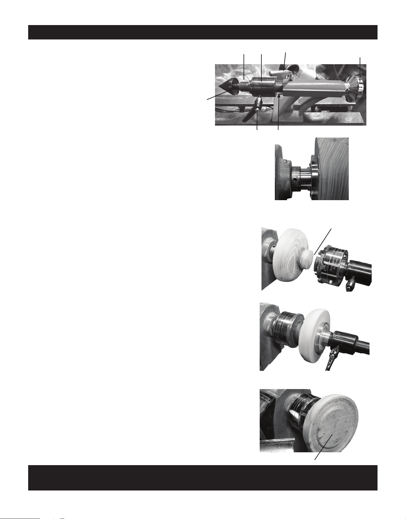
Using the features of the Tailstock
Reversing a bowl
When turning bowls, the outer pro le is turned rst and then the bowl is
hollowed. The most secure way to turn the outside is with the face-
plate, but the bowl must then be turned around for hollowing. This can
cause the bowl to be mounted off center when it is ipped. There are
accessories available to help ensure the blank remains centered, but
our tailstock bearing feature eliminates the issue without buying extra
accessories.
1. Mount a faceplate to one side of the bowl (Fig 1). This will be the
hollow side of the bowl. Thread faceplate and bowl blank onto the
headstock of the lathe and thread a 4 jaw chuck onto the tailstock.
Make sure the tailstock bearing is unlocked.
2. Turn the outer pro le of the bowl and a tenon at the bottom (Fig 2).
The tenon should be sized to be held in the 4 jaw chuck.
3. Slide tailstock forward (do not lock tailstock to bed yet). Close jaws
over the tenon. Lock tailstock to the bed and turn lathe to make sure
bowl is still centered between both sides.
4. Unlock tailstock from the bed and unthread bowl from headstock
while pulling tailstock away.
5. Unthread chuck and mounted bowl from tailstock and ip bowl so
that chuck can be mounted on headstock while still holding the bowl.
(Fig 3)
6. Turn lathe to make sure bowl is still centered and does not wobble.
To make extra sure, you can thread the faceplate onto the tailstock.
(Shown in Fig 3) Bowl should spin with no wobble
7. Unscrew faceplate and hollow out the bowl. (Fig 4)
Using the Live Tailstock
The Live Tailstock has the advantage of having a
bearing on the end of the tailstock that can spin with
a “dead” component installed. It can also be used tra-
ditionally with live components by locking the bearing.
The 1” x 8tpi threaded end allows mounting chucks and
other 1” x 8tpi accessories
Components of the Live Tailstock are:
1. 1” x 8tpi Threaded spindle end
2. Morse taper adapter inside the spindle
3. Bearing assembly
4. Bearing lock
5. Hand wheel to advance spindle
6. Quill
7. Locking lever
Mount bowl blank with faceplate
Assembly ipped and remounted
Hollow out bowl
Turned to t a 4” Jaw chuck
1
2
375
46
Patent Pending

Distributed by: © 2022 PSI Woodworking • Philadelphia, PA 19115
Manufactured by: Penn State Industries
TCLT10VS TCLT12VS PSI Woodworking Products
11
Fig 5
Fig 6
Drilling larger blanks (Fig 5)
Small blanks can be drilled on the lathe with the drill bit in a xed position and the blank spinning. This is harder to do with
large blanks, such as for pepper mills, since an unbalanced large blank can be dangerous to spin without tailstock support.
This set up will allow the lathe to be used for drilling without having a large blank spinning with only one side secured.
1. Mount Blank in 4 jaw chuck and mount chuck onto tailstock.
2. Lock the tailstock bearing.
3. Mount drill bit in headstock drill chuck
4. Line up drill bit with center of blank --this may require re-adjusting the chuck jaws.
5. Turn on lathe and advance tailstock quill to drill hole.
Use a double Maxi Mandrel for
secure mandrel hold (Fig 6)
Having a small amount of play on the tailstock is
typical with Mandrel Savers, because the rod has to
slide through the Saver. With the tailstock bearing,
You can mount the Mandrel using a Maxi Mandrel
collet on both the headstock and tailstock. With the
bearing unlocked, the mandrel rod is secured and
steady at both ends while turning.
Forstner bit with extension
Maxi Mandrel mounted in headstock Maxi Mandrel mounted in tailstock
Unlock Bearing
Drill chuck in headstock Lock Bearing
4 Jaw chuck
Turned to t a 4” Jaw chuck
Unlock Bearing
Unlock Bearing
Fig 7

TCLT10VS TCLT12VS PSI Woodworking Products
Distributed by: © 2022 PSI Woodworking • Philadelphia, PA 19115
Manufactured by: Penn State Industries
12
Appendix 2 PARTS DIAGRAM

Distributed by: © 2022 PSI Woodworking • Philadelphia, PA 19115
Manufactured by: Penn State Industries
TCLT10VS TCLT12VS PSI Woodworking Products
13
Part No. TCLT10VS TCLT12VS Description QTY
1 ZTCLC1 ZTCLC1Z Bed 1
2 ZTCLC2 ZTCLC2 Hex socket screw M10x25 2
2-1 ZTCLC2-1 ZTCLC2-1 Washer Ø10 2
3 ZTCLC3 ZTCLC3Z Handle 2
3-1 ZTCLC3-1 ZTCLC3-1 Retaining ring 4
4 ZTCLC4 ZTCLC4 Quill adjusting wheel 1
4-1 ZTCLC4-1 ZTCLC4-1 Bushing 1
4-2 ZTCLC4-2 ZTCLC4-2 Screw 1
5 ZTCLC5 ZTCLC5Z Long Tailstock Black 1
5-1 ZTCLC5-1 ZTCLC5-1 Cam follower tailstock 1
6 ZTCLC6Z ZTCLC6Z Handle Assy. 1
6-1 ZTCLC6-1 ZTCLC6-1 Lock bolt 1
7 ZTCLC7 ZTCLC7Z Eccentric axis 1
7-1 ZTCLC7-1 ZTCLC7-1 Tailstock retaining ring 1
8 ZTCLC8Z ZTCLC8Z Tailstock axis Long 5-5/8” 1
9 ZTCLC9 ZTCLC9 Tailstock quill /assy. 1
10 ZTCLC10 ZTCLC10 Tailstock Center 1
14 ZTCLC14 ZTCLC14 Headstock spur center 1
15 CF3J CF3J Face plate 1
16 ZTCLC16 ZTCLC16 Headstock spindle 1
17 ZTCLC17 ZTCLC17 Ball bearing 80105 2
18 ZTCLC18 ZTCLC18 Head stock retaining ring 2
19 ZTCLC19 ZTCLC19 Gear 1
20 ZTCLC20 ZTCLC20Z Round plastic plate 1
21 ZTCLC21 ZTCLC21Z Headstock assy. 1
21-1 ZTCLC21-1 ZTCLC21-1 Hex socket screw M8x30 4
21-2 ZTCLC21-2 ZTCLC21-2 Spring washer 4
21-3 ZTCLC21-3 ZTCLC21-3 Washer Ø8 4
22 ZTCLC22 ZTCLC22 Drive pulley 1
23 ZTCLC23 ZTCLC23Z Side protection guard 1
24 ZTCLC24 ZTCLC24 Hand wheel 1
24-1 ZTCLC24-1 ZTCLC24-1 Socket set screw M6x12 7
25 ZTCLC25 ZTCLC25 Side plate 1
25-3 ZTCLC25-3 ZTCLC25-3 Connecting rod 1
26 ZTCLC26 ZTCLC26 Connecting plate 1
26-1 ZTCLC26-1 ZTCLC26-1 Round head bolt M3x12 1
26-2 ZTCLC26-2 ZTCLC26-2 Round head bolt M4x10 6
26-3 ZTCLC26-3 ZTCLC26-3 Hex nut M3 1
26-4 ZTCLC26-4 ZTCLC26-4 Spring washer Ø3 1
26-5 ZTCLC26-5 ZTCLC26-5 Washer Ø3 1
26-6 ZTCLC26-6 ZTCLC26-6 Spring washer Ø4 2
26-7 ZTCLC26-7 ZTCLC26-7 Washer Ø4 2
27 ZTCLC27 ZTCLC27 Display plate 1
27-1 ZTCLC27-1 ZTCLC27-1 Tapping screw 4
27-2 ZTCLC27-2 ZTCLC27-2 Connector 1
28 ZTCLC28 ZTCLC28Z Display housing 1
28-1 ZTCLC28-1 ZTCLC28-1Z Seal ring 1
30 ZTCLC30 ZTCLC30Z Rear plate 1
30-1 ZTCLC30-1 ZTCLC30-1 Moving knob 1
30-2 ZTCLC30-2 ZTCLC30-2 Stationary knob 1
30-3 ZTCLC30-3 ZTCLC30-3 Screw 1
30-4 ZTCLC30-4 ZTCLC30-4 Screw 1
Part No. TCLT10VS TCLT12VS Description QTY
31 ZTCLC31 ZTCLC31 Connecting stand Assembly 1
32 ZTCLC32 ZTCLC32Z Stop bolt Assembly 1
33 ZTCLC33 ZTCLC33 Work light 1
33-1 ZTCLC33-1 ZTCLC33-1 Hex nut M12 1
34 ZTCLC34 ZTCLC34Z Tool rest 6” 1
34-1 ZTCLC34-1 ZTCLC34-1Z Tool rest 12” 1
35 ZTCLC35 ZTCLC35Z Tool rest base 1
36 ZTCLC36 ZTCLC36 Bushing 1
37 ZTCLC37 ZTCLC37Z Lock handle for tool rest base 1
37-1 ZTCLC37-1 ZTCLC37-1 Tool rest retaining ring 2
38 ZTCLC38 ZTCLC38 Toolrest Locking Handle assy 1
39 ZTCLC39 ZTCLC39 Tool rest cam follower 1
40 ZTCLC40 ZTCLC40 Step washer 2
41 ZTCLC41 ZTCLC41 Lock nut M10 2
42 ZTCLC10VSB ZTCLC10VSB Control Switch box 1
42-2 ZTCLC42-2 ZTCLC42-2 Washer Ø4 3
42-3 ZTCLC42-3 ZTCLC42-3 R.H. machine screw M4x25 3
42-4 ZTCLC42-4 ZTCLC42-4 Control box switch 1
42-5 ZTCLC42-5 ZTCLC42-5 Control box speed control knob 1
45 ZTCLC10VMO ZTCLC12VMO Motor 1
45-1 ZTCLC45-1 ZTCLC45-1Z Motor guard 1
45-2 ZTCLC45-2 ZTCLC45-2 Round head bolt M4x10 1
45-3 ZTCLC45-3 ZTCLC45-3 Nut M6 1
46 ZTCLC6 ZTCLC6 Handle 1
46-1 ZTCLC46-1 ZTCLC46-1 Lock Washer 1
47 ZTCLC47 ZTCLC47Z Motor plate with notch 1
47-1 ZTCLC47-1 ZTCLC47-1 Washer Ø6 1
47-2 ZTCLC47-2 ZTCLC47-2 Hex socket screw M8x16 1
47-3 ZTCLC47-3 ZTCLC47-3 Spring washer Ø4 3
47-4 ZTCLC47-4 ZTCLC47-4 Hex socket screw M6x16 3
47-5 ZTCLC47-5 ZTCLC47-5 Washer Ø8 1
47-6 ZTCLC47-6 ZTCLC46-6Z Guard 1
47-7 ZTCLC47-7 ZTCLC47-7 Round head bolt M4x16 2
48 ZTCLC48 ZTCLC48Z Motor pulley 1
49 ZTCLC1049W ZTCLC1249W Drive belt 1
50 ZTCLC50 ZTCLC50 Adjustable Rubber Feet 4
51 ZTCLC51 ZTCLC51 Knob 1
51-1 ZTCLC51-1 ZTCLC51-1 Spring 1
51-2 ZTCLC51-2 ZTCLC51-2 Bolt M8 1
51-3 ZTCLC51-3 ZTCLC51-3 Washer Ø8 1
51-4 ZTCLC51-4 ZTCLC51-4 Nut M8 1
52 ZTCLC52 ZTCLC52 Mounting plate 1
52-1 ZTCLC52-1 ZTCLC52-1 Pin hinge 1
52-2 ZTCLC52-2 ZTCLC52-2 Hinge 2
52-3 ZTCLC52-3 ZTCLC52-3 R.H. machine screw M4x8 6
52-4 ZTCLC52-4 ZTCLC52-4 Washer Ø4 6
53 ZTCLC53 ZTCLC53 Ball 1
54 ZTCLC54 ZTCLC54 Knock-out rod 1
55 ZTCLC55 ZTCLC55 Tool rack 1
55-1 ZTCLC55-1 ZTCLC55-1 R.H. machine screw M5x12 7
55-2 ZTCLC55-2 ZTCLC55-2 Washer Ø5 8
56 ZTCLC56 ZTCLC56 Cable Support 2

TCLT10VS TCLT12VS PSI Woodworking Products
Distributed by: © 2022 PSI Woodworking • Philadelphia, PA 19115
Manufactured by: Penn State Industries
14
ACCESSORIES AVAILABLE FROM PSI WOODWORKING
PRODUCTS FOR YOUR TURNCRAFTER TAILSPINNER LATHE
Item Description Typical Products
Lathe Extension Bed Extends the lathe and Spindle you can turn to 42” #TCLC10XB for 10”Style
#TCLC12XB for 12”Style
Duplicating Attachment Enables duplicating small projects to 9” long. Makes fast and easy copies. #CML-DUPMAX
Chucks "To mount up a variety of work on to your headstock. Styles include drill chucks, mini
chucks, screw chucks, col-
let chucks and chuck styles for larger work."
#CSC3500SE Versatile self centering multi compo-
nent system.
Plus many other styles available."
Pen Mandrels "Essential for making pens and other small projects on
your lathe. Mounts pen blanks for turning and finishing."
#PKM-FLC - Fits into the #MT2
opening in the headstock"
Lathe Tools Skew Chisels - for final finishing and smooth cuts and beading #LX010 1/2” plus others
Parting Tools - to trim o waste establish a diameter or cut flat areas #LX410 1/2” plus others
Roughing Gouges- For aggressively taking square spindles to a round #LX260 1”plus others
Spindle Gouges - For general purpose turning a spindle from rough round to a near
finish. A favorite for pens.
#LX320 3/8” plus others
Scrapers - For smoothing and for interior clean up inside a bowl after gouge work is
completed.
#LX120 1” plus others
Bowl Gouges - Used for hollowing out bowl centers. Used on most faceplate work. #LX210 3/8” plus others
Lathe Tool sets - Include a variety of sizes and styles of the above. #LCHSS8 - 8 pc variety
Other specialty sets available"
Carbide Chisels with replacement cutter #LCWIZ - 3pc set
Carbide 6 sided negative rake cutter #LCWIZR6 - Negative rake cutter
Specialty Tools for: Making beads and coves, interior and exterior bowl finishing,
bowl hollowing, making tenons and dovetails and more.
#LCHOLSET - Bowl hollowing set with replaceable
cutters and others
Faceplates "For Mounting bowls. Many sizes are available depending
on the size of the bowl being turned."
#CF2 - 6” faceplate many other sizes
available"
Drive Centers Many styles available for special applications #LCENTSS21 - Super drive
multi prong style plus others"
Toolrests Many special profiles available for bowl turning, longer
work, shorter work."
#CLTSJ -“S”toolrest for bowl
turning plus others"
Other Equipment Specialty items to use with your lathe include: sanding systems, special chuck jaws,
measuring
and marking products, tailstock centers, mandrel saver and more."
APPENDIX 3

© 2013 PSI Woodworking • Philadelphia, PA 19115 v5/13
Distributed & Manufactured by: © 2016 PSI Woodworking • Philadelphia, PA 19115
Distributed by: © 2022 PSI Woodworking • Philadelphia, PA 19115
Manufactured by: Penn State Industries

Distributed & Manufactured by: © 2016 PSI Woodworking • Philadelphia, PA 19115
Distributed by: © 2022 PSI Woodworking • Philadelphia, PA 19115
Manufactured by: Penn State Industries
This manual suits for next models
1
Table of contents
Other PSI Woodworking Lathe manuals


Popular Lathe manuals by other brands


steinert
steinert KM 3100 SE operating instructions

VEVOR
VEVOR MCS1000 instruction manual

Gude
Gude GDM 1000 Translation of original operating instructions

tornos
tornos MultiDeco Series Equipment Logbook Assembly, operation and maintenance

Baileigh
Baileigh WL-1220VS Operator's manual

Scheppach
Scheppach DM500T Translation of original instruction manual


