PSL D600 User manual

OWNERS MANUAL
D600
Rev: 4: 07/22
Portable Pump

2
NOTE: This manual is an integral part of the pump
package and MUST be read before operating the unit.
This manual must be kept and regularly referred to
throughout the lifetime of the equipment. Failure to do
so could result in injury and damage to the equipment.
Please ensure that any amendment received is
incorporated in the text and that this manual is passed
on to any subsequent holder or user of the equipment.

3
Manufactured by Vortex Holdings Ltd
31 Murchison Street Tikokino Central Hawkes Bay New Zealand. Tel +64 21435811
www.firepumps.co.nz email admin@firepumps.co.nz Page 2of 14
Health and safety
WHEN ENGINE IS RUNNING DO NOT:
1. Run with any guard removed.
2. Attempt any work in the guarded area.
3. Attempt to move the unit.
4. Refill the fuel tank (without removing it from the frame into a safe area first)
5. Remove the pressure cap from the expansion tank (wait until the engine has cooled.)
6. Place hands inside the volute housing.
7. Place any part of body near suction inlet. (If running with no suction hose connected,
always connect the end cap.)
WHEN ENGINE IS RUNNING DO:
8. Run the unit on level ground wherever possible. Inclination must never exceed 45°.
9. Check all couplings are secure before increasing pressure.
10. Wear ear protection when working near a running pump. It is also advised that eye
protection is used. Loose fitting clothing should not be worn whilst operating the pump.
WARNING: The gas priming exhaust reaches extreme temperatures.
WARNING: This pump weighs 122Kg (dry with 2 X Batteries)
WARNING: The pump should not be run in underground or poorly ventilated spaces.
WARNING: The guards on the exhaust side of the engine can become hot after prolonged
running at high speed.
WARNING:This pump can emit Noise levels over 85dB and ear protectors should be worn
at all times when running the pump.
WHEN ENGINE IS NOT RUNNING:
1. Do not place any heavy or loose items on the unit.
2. Do not drop the unit from any height.
MAINTENANCE
1. Allow the unit to cool before attempting to remove any part.
2. Before starting any maintenance ensure the ignition switch is off and disconnect one battery
lead or remove the battery.
3. Use only authorised spare parts supplied by Phoenix Firepumps or Lombardini / Kohler
WARNING
The pump body, when delivering water under pressure, is a pressure vessel. Failure to
assemble the pump body correctly can lead to leaks or in extreme cases failure of the pump
body. Ensure that the body is correctly positioned and that all bolts are tightened using a
spanner of the correct size and length.
DISPOSAL OF DIESEL FUEL AND OIL
Always dispose of surplus diesel and oil from the engine in a safe and environmentally safe
way. Only use receptacles specifically provided for diesel and oil.
Only dispose of surplus diesel and oil at authorised sites.

4
Manufactured by Vortex Holdings Ltd
31 Murchison Street Tikokino Central Hawkes Bay New Zealand. Tel +64 21435811
www.firepumps.co.nz email admin@firepumps.co.nz Page 3of 14
TO THE OPERATORS OF THE
D600 PORTABLE FIRE PUMP
Your new Phoenix D600 fire pump will deliver years of efficient and trouble free service if given
reasonable care and properly operated.
A study of the following pages should enable you to overcome any difficulties, which might
arise in the operation of this equipment. We request that you read this manual carefully before
placing this fire pump into service.
Several pages of useful data are contained herein to help you answer many of the questions
that may arise relative to the hydraulics of fire fighting.
PLEASE RETAIN THIS MANUAL FOR FUTURE REFERENCE
WARRANTY
Phoenix Firepumps unconditionally guarantees to replace, for a period of two years, any
defective part or parts in the D600 pump.
Every new D600 pump is guaranteed to deliver performance as specified in our sales brochure.
This warranty does not obligate us to bear costs of labour or transportation charges incurred in
the replacement of parts.
We shall not be responsible, under the terms of this warranty, for the cost of repairs or
alterations not authorised by us.
We shall not be responsible for damages or contingent liabilities resulting from failures of any
Phoenix pump.
We make no warranty of any trade accessories incorporated in the assembly or employed in
conjunction with any phoenix pump.
Excessive overloading of this pump beyond our recommended limits of capacity and pressure
shall void this warranty.

5
Manufactured by Vortex Holdings Ltd
31 Murchison Street Tikokino Central Hawkes Bay New Zealand. Tel +64 21435811
www.firepumps.co.nz email admin@firepumps.co.nz Page 4of 14
OPERATION OF D600 FIRE PUMPS
SUMMARY OF WHAT TO REMEMBER
1. Close delivery valves and drain valves, before attempting to prime pump.
2. Always keep primer shut off valve closed when working from hydrants or relay pumping.
3. Open primer-operating valve fully with 1/4 throttle to re-prime or eliminate trapped air
from suction line.
4. Never run pump without water in it except during priming.
5. Accelerate and retard speed of engine gradually.
6. Watch gauges periodically to ensure pump is operating normally.
7. Keep good gaskets in suction hose, and handle carefully to avoid damage to coupling
threads.
8. Air leakage into suction line is the most frequent source of trouble when pumping from a
suction lift.
9. Always use a suction strainer when pumping from open water.
10. Foreign matter in impellers is a result of failure to use adequate strainers and a common
source of trouble.
11. Drain pump immediately after each run.
12. Check oil level in motor after each pumping run.
13. Do not run a pump long with discharge completely shut off.
14. Do not close a “shutoff” type nozzle when pumping with throttle wide open.

6
Manufactured by Vortex Holdings Ltd
31 Murchison Street Tikokino Central Hawkes Bay New Zealand. Tel +64 21435811
www.firepumps.co.nz email admin@firepumps.co.nz Page 5of 14
Engine Operation
General information.
D600 Diesel series pumps use Lombardini / Kohler diesel engines. This is a two cylinder,
overhead valve, air-cooled engine. All drilled/tapped holes and fasteners on this engine are ISO
metric. However, where the pump attaches to the engine SAE standards apply.
This engine will operate satisfactorily at any angle at which the operator and pump can function
safely but not exceeding a maximum inclination 0f 35 degrees
Engine power will decrease 1% for each 100 metres above sea level and 2 % for each 5
degrees above 20 degrees Celsius. However, the pump unit has been design so, as no
perceptible loss of pumping will be noticed up to 1500 metres.
Important Information Running in:
During the first 50 hours of operation do not exceed 70% of the maximum rated
output.
Starting and Stopping
Before starting engine
•Use the correct oil for the starting temperature expected.
•Check the engine oil level. If the oil level is under the minimum, fill up.
•Unscrew the fuel cap and visually inspect the fuel level.
•If the fuel has been drained use the manual pump on the fuel pump to prime the injector
pump.
•A warm battery has more starting capacity than a cold battery.
•Set speed control at half throttle position
•Ensure the “Stop” control is fully closed.
•Turn key to start.
•Once engine has started release the key so it returns to the on position, and throttle back to
idle position.
•If the fuel circuit has been emptied or in harsh weather, several attempts may be necessary
before the engine starts. In such cases, alternate a 15 second attempt with a 15 second
pause to avoid overheating the starter motor.
Note:
This D600 pump is fitted with two REC 22 batteries wired in parallel. This gives a built in
redundancy should one battery fail.
Charge batteries fully before trying to start engine fitted with electric starting.
Stopping the engine
Move the throttle control to the SLOW position wait for a few seconds, and then turn the key to
the OFF position and pull the stop control fully out to stop the engine. (See Fig: 1 Below)
Fig: 1
Pull up to stop engine
7
Manufactured by Vortex Holdings Ltd
31 Murchison Street Tikokino Central Hawkes Bay New Zealand. Tel +64 21435811
www.firepumps.co.nz email admin@firepumps.co.nz Page 6of 14
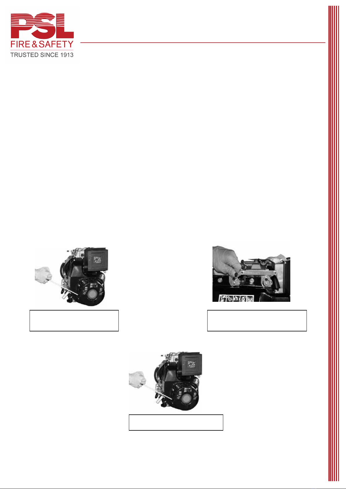
Starting The Engine If The Electric Start Will Not Turn The Engine Over:
Starting the engine with the recoil starter can be difficult if not practiced as the compression
ratio of a diesel engine is high. However with practice and the right technique the engine will
start with the recoil starter by following the recommended steps below.
1. Turn the key to the “On” position. Ensure the stop control is fully in the closed
position.
2. Pull the rope starter until the engine comes up to compression.
3. Pull the decompression lever fully forward.
4. Using 2 hands on the starter handle and 1 foot firmly placed on the bottom of the
pump frame.
5. Give one hard pull (you need to be strong enough to get it to roll over the
compression stroke to fire)
6. Remember the compression ratio of a diesel engine is 19:1 so you really need to
pull hard with two hands or if the person is small or weak have two people pull
on the starter rope with one person holding down the pump.
.
2: Pull decompression levers over. The
starting position is correct only if the levers
remain engaged.
3: Let the starter cord recoil back into
position, then pull starter cord hard.
1: Pull the rope starter until the engine
comes up to compression.

8
Manufactured by Vortex Holdings Ltd
31 Murchison Street Tikokino Central Hawkes Bay New Zealand. Tel +64 21435811
www.firepumps.co.nz email admin@firepumps.co.nz Page 7of 14
Priming the LD600 Pump
Operating the primer
The D600 primer should typically develop up to minus 0.6 bar in an airtight pumping system.
The primer is an exhaust-eject type, extremely reliable and requires only minimal maintenance.
The primer is activated by a combination spring return, on-off valve connected to the exhaust
system and a one-way valve situated at the pump inlet. Pulling the valve closes off the exhaust
outlet redirecting the gases through the primer. The velocity of the passing exhaust gases
causes a vacuum at the primer, which lifts the one-way valve off its seat and evacuates the air
in the pump and suction line.
A ball valve is located immediately after the one-way valve and should only be closed if the
pump inlet is under pressure, i.e. when pumping in closed circuit relays or from a hydrant
supply.
Before the pump can be primed, delivery valves, drain valves, and other openings to the pump
must be closed and absolutely air tight.
When operating from draft, suction hose connections must be tight and free of air leaks.
Make certain the suction hose strainer is properly submerged and free from foreign material.
Pull the primer valve all the way out and open throttle up to 50% revs to start priming.
Hold the valve open until water discharges from the primer exhaust port and a positive reading
shows on the delivery gauge. Crack open delivery valve to flow water. Push valve all the way
in to shut off primer and throttle back.
If water does not discharge from primer exhaust within about 40 seconds, stop priming and
check for air leaks.
The primer should achieve a 1-metre lift within 10 seconds and a 3-metre lift within 30 seconds
using 4” (100mm) suction hose.
When pumping from hydrants, the primer is not needed and must be kept closed.

9
Manufactured by Vortex Holdings Ltd
31 Murchison Street Tikokino Central Hawkes Bay New Zealand. Tel +64 21435811
www.firepumps.co.nz email admin@firepumps.co.nz Page 8of 14
PUMP OPERATION
Source of water supply
Water may be drafted from a pond, lake, stream, cistern, stock tank, or well but, whatever the
source, the static lift must not exceed 5 metres (16 ft) from the center of the pump to the
surface of the water, and a lift not exceeding 3 metres (10 ft) is recommended. The source of
supply should be reasonably clear and free from foreign matter. It is recommended that all
water holes, which may be needed for fire protection, be deepened if necessary and kept free
from weeds and refuse. In many fire protection areas, cisterns or reservoirs are built and
allowed to fill up with rainwater to allow them to be used in emergencies.
Pumping in cold weather
The first insurance against cold weather trouble is to keep fire apparatus stored in heated
quarters. All water must be eliminated from pump casing and primer line between periods of
operation.
When setting up for pumping, unnecessary delays should be avoided by having thoroughly
trained pump operators. Be sure that the primer and hose lines are kept closed until ready for
use. Have hose lines ready so that the pump may be started as soon as it has become primed.
Do not stop flow of water through the pump until ready to drain and return to station.
When finished pumping
Drain water out of pump casing immediately. (Drain valve is located at lowest point in pump
casing).
Do not forget to close the drain valve after all water has been drained out. Trouble in priming
will follow on the next run if this is forgotten.
Pumps not often used for fire service should be inspected and run periodically to ensure that
they will be in readiness for an emergency.
Pumping salt water
The pump should be flushed out with fresh water immediately after pumping salt water to
prevent excessive corrosion.
A centrifugal pump will show 2½% higher pressure and require 2½% more power when
handling seawater than when handling fresh water, if operated at the same speed and capacity.
Use of pump for emergency practices
It frequently happens that operators of a portable fire pump, who are not thoroughly familiar
with its operation, become confused under the stress of an emergency and neglect some small
detail that may cause trouble or delay in getting the equipment into operation. Therefore, we
strongly urge that practice tests be conducted repeatedly until operators are thoroughly trained.
More than one person in the brigade should be a competent operator.
Practice should include pumping from low lifts, high lift with short and long suction lines, with
suction line elevated to form an air trap, and from hydrants, at large and small capacities.
It is well, also, to note the effects of air leaks in hose, insufficient submergence and restriction
of suction line (suction line can be restricted by placing a can or strong closure around the
suction strainer).
NEVER BREAK OR RESTRICT SUCTION OR ADMIT AIR INTO SUCTION LINE WHILE
MOTOR IS OPERATING WITH THROTTLE OPEN. This will release the load and could allow
the motor to over speed.

10
Manufactured by Vortex Holdings Ltd
31 Murchison Street Tikokino Central Hawkes Bay New Zealand. Tel +64 21435811
www.firepumps.co.nz email admin@firepumps.co.nz Page 9of 14
PUMP TESTING
Measurement of pump performance
Pump performance is measured by the quantity of water it can deliver per minute against a
certain pressure called “Total Head”, or “Net Pump Pressure” as it is usually termed in fire
pump testing.
The Net Pump Pressure is the sum of the pump discharge pressure as shown on the pressure
gauge with which the pump is equipped, and the total suction lift converted to equivalent kPa.
If a pump is operating from a hydrant, the Net Pump Pressure is the discharge pressure less
the incoming pressure from the hydrant measured at the suction entrance to the pump.
Capacity of a fire pump is measured in litres per minute. The usual method of measurement is
to determine the pressure of the jet of water leaving a given size nozzle by means of a “Pitot
Gauge” from which the capacity is computed mathematically.
A Pitot Gauge consists of a small tube adapted so as to point directly into the nozzle from the
center of the issuing stream, the other end of the tube being connected to an accurate pressure
gauge.
The nozzle jet drives straight into the Pitot tube and converts the velocity of the jet into
pressure, which is an accurate measure of the velocity of the water as it leaves the nozzle. The
tip of the Pitot tube should be one-half the diameter of the nozzle away from the nozzle tip while
taking readings.
If a Pitot Gauge is not available, approximate pump capacities can be determined by reference
to the following chart.
Flow rate
(Liters/minute)
Pump Pressure
Nozzle Size
13
16
19
22
23
25
28
32
(KPa)
(mm)
100
111.5
169
238
319
349
412
517
676
200
157
239
337
451
493
583
731
955
300
193
292
412
553
605
714
896
1170
400
223
338
476
638
698
825
1035
1351
500
249
378
532
714
780
922
1157
1511
600
273
414
583
782
855
1010
1267
1655
700
295
446
630
844
923
1091
1368
1787
800
315
477
673
903
987
1166
1463
1911

11
Manufactured by Vortex Holdings Ltd
31 Murchison Street Tikokino Central Hawkes Bay New Zealand. Tel +64 21435811
www.firepumps.co.nz email admin@firepumps.co.nz Page 10 of
14
Oil and Fuel Recommendations
Check oil level regularly. See oil chart, capacity, checking and filling procedures.
Always refer to engine manufacturers handbook
Maintain correct oil level. Check daily before starting engine.
Change Oil
Change oil after the first 50 hours of operation. Drain oil while engine is warm.
Note: Change oil there after every 50 hours of operation or yearly.
Lubricants
Use diesel engine lubricants which meet APICC 2104B specifications. A multigrade oil such as
AGIP SUPER DIESEL MULTIGRADE 15W/40 can be used.
If the engine is used in places with temperatures under –15 degrees celcius, use SAE 5W/30
oil.
Oil Capacity.
Approximately 1.8 Litres
Fuel Recommendations
•Fuel vapours are highly toxic. Only carry out refueling operations outdoors or in a well-
ventilated area.
•When refueling it is advisable to use a funnel to prevent fuel from spilling out. The fuel
should also be filtered to prevent dust or dirt from entering the tank.
•Use the same type of diesel fuel as used in cars or trucks. The use of other types of
fuels could damage the engine.
•The Cetane rating of the fuel must be higher than 45 to prevent difficult starting.
•Do not use dirty diesel fuel or mixtures of fuel and water this will cause serious engine
faults.
•Do not fill the fuel tank completely, but just up to 1cm from the top of the tank, to provide
space for fuel movement. Wipe any fuel spillage from engine before starting.

12
Manufactured by Vortex Holdings Ltd
31 Murchison Street Tikokino Central Hawkes Bay New Zealand. Tel +64 21435811
www.firepumps.co.nz email admin@firepumps.co.nz Page 11 of
14
Service, Storage & Specifications
For engine service.
See an Authorized Kohler / Lombardini Service Dealer. Each one carries a stock of Genuine
Kohler / Lombardini Parts and is equipped with special service tools. Trained mechanics assure
expert repair service.
Only dealers advertising as “Authorized Kohler or Lombardini Dealer” are required to meet
Kohler / Lombardini standards.
Pump Service.
Most Authorized Kohler / Lombardini dealers are capable of performing minor repairs and
adjustments to the pump components. Any major repairs or overhauls should be returned to the
factory or referred back to the importer to assure expert repair service.
Storage Instructions.
The engine components may rust over time, especially if left inactive, prejudicing the efficiency
and performance of the machine. A number of precautions are set out below, which may prove
useful if the engine is left unused for long periods.
Storage up to 6 months
•Run the engine without load and at low speed for about 15 minutes and the switch off.
•Change the fuel filter.
•Disconnect Batteries.
•Pour a mixture of diesel and AGIP RUSTIA 81 (10%) into the fuel tank;
•Run the engine for about 10 minutes at a speed of between ½and ¾nominal RPM, so
that the tubes, injector pump And filters are filled with the protective mixture, then switch
off.
•Spray AGIP RUSTIA C SAE 30 into the exhaust and intake ducts and manually turn
with starting recoil.
•Thoroughly clean the fins and external parts of the engine and protect the unpainted
external surfaces with AGIP RUSTIA C 30.
•Seal the silencer and air filter with adhesive tape.
•Wrap the engine in a plastic sheet.
Storage for more than 6 months
In addition to the above operations, do the following:

13
Manufactured by Vortex Holdings Ltd
31 Murchison Street Tikokino Central Hawkes Bay New Zealand. Tel +64 21435811
www.firepumps.co.nz email admin@firepumps.co.nz Page 12 of
14
•Change or wash the oil filter
•Replace the engine oil with AGIP RUSTIA C SAE 30.
•Periodically inspect the engine and check that there are no traces of rust or corrosion, if
present, consult a Kohler assistance center.
Re-commissioning
•Remove the protective covers.
•Remove the external protective product with solvent or a degreasing agent.
•Check the setting of the injectors, the clearances of the valves and the tightness of the
heads and filters.
•Carry out the normal preliminary checks prior to starting the engine.
•If protective oil such as AGIP RUSTIA C SAE 30 has been used, change it after not
more than 100 hours of work.
Tune-up specifications: refer to engine manufacturer’s handbook for additional
information.
Valve clearance cold intake and exhaust .006 in (0.15 mm).
Electrical
Batteries: Two X Yuasa 12 Volt REC 22
•Check battery Condition using a voltmeter, voltage should not be below 12 volts. If voltage
is below 12 volts recharge the battery by connecting battery charger through the 12-volt
accessory socket on the dash.
•Clean battery terminals from time to time.
•Always maintain battery in good charged condition
•Battery should be Charged once a month when not in use
Battery Charging.
The engine has a built in alternator with an output of 16 amps

14
Manufactured by Vortex Holdings Ltd
31 Murchison Street Tikokino Central Hawkes Bay New Zealand. Tel +64 21435811
www.firepumps.co.nz email admin@firepumps.co.nz Page 13 of
14
TROUBLESHOOTING
Refer to engine manufacturer’s handbook for additional information.
DEFECT CAUSE
•Fails to start. Incorrect fuel. Air in fuel. Fuel tank empty.
•Starts and stops Air filter clogged. Air in fuel. Diesel filter clogged.
•Lack of power Air filter clogged. Diesel filter clogged.
•Light Blue smoke. Too much oil in crankcase.
•Black smoke. Excessive load.
•Knocking in head area. Incorrect fuel.
•High oil consumption. Too much oil in crankcase.
•Leaks oil. Vent tube bent.
•Oil comes out of exhaust. Engine running in.
•Overheats. Head and cyl fins clogged. Excessive load.
•Misfires. Incorrect fuel. Air in fuel. Engine cold. Tank vent.
•No increase in rpm. Incorrect fuel. Air in fuel. Tank Vent clogged.
The above troubleshooting guide is a general outline of the main causes of defects, which the
operator can easily remedy. In the case of more serious problems it is advisable to contact a
Kohler / Lombardini service center.

15
Manufactured by Vortex Holdings Ltd
31 Murchison Street Tikokino Central Hawkes Bay New Zealand. Tel +64 21435811
www.firepumps.co.nz email admin@firepumps.co.nz Page 14 of
14
D600 FIRE PUMPS
DATA SUMMARY
1. General Description.
The pump set consists of two cylinder air-cooled diesel that is coupled to a single stage centrifugal
pump.
The Pump set consists of the following main components:
A: Kohler KD 425-2 diesel engine
B: Phoenix Centrifugal pump end
C: Exhaust ejector primer
D: Stainless Steel Carry Frame.
2. Manufacturers Data
The Manufacturers details are:
Vortex Holdings Ltd
31 Murchison Street
Tikokino 4273
New Zealand
Tel +64 (6) 21 435811
Email adm[email protected]
Web site www.firepumps.co.nz
3. Physical Data
Dimensions and mass:
A: Length 760mm
B: Width 530mm
C: Height 550mm
D: Weight 122 kg (With Twin Batteries)

16
Manufactured by Vortex Holdings Ltd
31 Murchison Street Tikokino Central Hawkes Bay New Zealand. Tel +64 21435811
www.firepumps.co.nz email admin@firepumps.co.nz Page 15 of
14
DATA SHEET CONT.
4. Engine
A: Make Kohler / Lombardini
B: Model KD 425
C: Type 4 stroke, overhead valve, air-cooled, diesel engine
D: Bore & Stroke 85X 75mm
E No of cylinders 2
F: Displacement 851 cc
G: Fuel Tank capacity 4 litres
H: Fuel Type Diesel
I: Lubrication Forced with lobe pump
J: Starting System Recoil or electric if fitted
K: Battery 12 Volt
5. PUMP
A: Make Phoenix Maxflo
B: Type Centrifugal
C: Discharge Rate model M 600 Litres/min @ 700 kPa
D: Discharge Port size 50 mm
E: Primer Type Exhaust Eject
F: Maximum draft height 7.5 metres
G: Discharge Valve 2 X Globe valves 50mm BSP
6. Couplings
A: Suction 100mm round thread
END
Table of contents
Other PSL Water Pump manuals

Popular Water Pump manuals by other brands

Power Craft Garden
Power Craft Garden 71999 instruction manual

Gianneschi
Gianneschi CP Series operating manual

Wilo
Wilo VeroLine-IP-E Series Installation and operating instructions

GORMAN-RUPP
GORMAN-RUPP SFEV3C Installation, operation and maintenance manual

Speck pumpen
Speck pumpen BADU Eco Touch-pro manual

WDM
WDM ME Series Operation manual

Bosch
Bosch AGS10-2 Installation and servicing instructions

HNP Mikrosysteme
HNP Mikrosysteme mzr-2509 Ex operating manual

Holmatro
Holmatro HTW Series manual

Monarch Industries
Monarch Industries ACT-SD Series owner's manual

Villager
Villager JGP 1100 F Original instructions

Omega Engineering
Omega Engineering FPU4500 user guide


