Tait TB8100 Installation instructions

Tait Confidential Tait Electronics Ltd
Telephone:+64-3-357-9991 TN-1013-AN
http://support.taitworld.com Date of Print: 12/03/07 Page 1 of 9
Applicability TB8100 Base station.
T805 Simulcast Remote Site Unit (RSU).
1Introduction
The TB8100 base station is suitable for use in simulcast systems with the
Tait T805 RSU. This technical note aims to explain what you specifically
need to do to use the TB8100 base station in a simulcast system: order the
correct TB8100 equipment, make the necessary hardware connections, and
configure the TB8100 base station (using the Service Kit application).
2Related Documentation
The following documentation is related to this technical note:
TB8100 Service Kit Users Manual or the on line help.
TB8100 Installation and Operation Manual.
TB8100 Specifications Manual.
Taitnet QS2Simulcast System Manual.
3Equipment Required
3.1 TB8100 PMU and Rackframe
If you intend to use the TB8100 base station in a simulcast system, make
sure that you specify these options when you order the TB8100:
TBA30xx-x100 PMU with internal 13.8 V DC 40 Watt auxiliary power
supply. This is used to supply power to the external frequency
reference and the RSU. Please refer to the TB8100 specifications
manual for product code information.
If the RF links are also using TB8100 system components, a TBA2520
dual channel rackframe should be used
3.2 T805-26-XY0Z
The last four numbers of
the equipment specify the
RSU equipment
configuration.
X = 0, Grey/Beige front panel
8, Black front panel
Y= 1 to 4, Number of QS2 Channel Cards fitted
Z= 0, GPS receiver not fitted
= 1, GPS receiver fitted
TECHNICAL NOTE TN-1013-AN
Using the TB8100 Base Station in Tait
QS2Simulcast Systems
9 March 2007

Tait Confidential Tait Electronics Ltd
Telephone:+64-3-357-9991 TN-1013-AN
http://support.taitworld.com Date of Print: 12/03/07 Page 2 of 9
4Connecting the TB8100 to the T805 Equipment.
4.1 DB25 SIF Connections using TBA40xx-0B00 & TBA40xx-0C00 Reciters.
RSU J414 on T805 TB8100 SIF
Function Pin Pin Function
RX Audio + 1 1 RX Line Out +
RX Audio - 2 2 RX Line Out -
CTCSS Output 3 5 TX Audio In
TX Key 4 10 TX Key
Ground 5 4 Ground
RX Gate 6 9 RX Gate
TX Audio + 7 6 TX Line In +
TX Audio - 8 7 TX Line In -
4.2 TaitNet SIF Connections using TBA40xx-0K00, TBA40xx-0L00 or
TBA40xx-0T00 Reciters.
RSU J414 on T805 TB8100 SIF
Function Pin Pin Function
RX Audio + 1 1 RX Line Out +
RX Audio - 2 2 RX Line Out -
CTCSS Output 3 6 TX Audio In
TX Key 4 5 TX Key
Ground 5 15 Ground
RX Gate 6 4 RX Gate
TX Audio + 7 7 TX Line In +
TX Audio - 8 8 TX Line In -

Tait Confidential Tait Electronics Ltd
Telephone:+64-3-357-9991 TN-1013-AN
http://support.taitworld.com Date of Print: 12/03/07 Page 3 of 9
5Configuring the Reciter
5.1 Configuring the Auxiliary Power Supply and External Reference.
Service Kit Menu Item (SK): Configure > Base Station > Miscellaneous
Configure the following
parameters.
The specific changes that you will need to make to the TB8100 base
station’s configuration file (using the Service Kit application) are as follows.
(For further information on using the Service Kit, please refer to the Service
Kit User’s Manual or the online help). The following procedure assumes the
use of the default template, available in File > New and choose the
default.t8t file.
1. Set auxiliary power supply to 'Task Manger '.
2. Select the relevant external reference frequency, either 10 MHz or
12.8 MHz.
Select Frequency of
External Reference to
10MHz or 12.8MHz.
Aux power Control set to
Task Mana
g
er.

Tait Confidential Tait Electronics Ltd
Telephone:+64-3-357-9991 TN-1013-AN
http://support.taitworld.com Date of Print: 12/03/07 Page 4 of 9
Configuring the Auxiliary Power Supply and External Reference
continued.
SK: Configure > Base Station > Task Manager
Configure the following
parameters.
1. Enable the If Base station in run mode Then Enable auxiliary supply
statement. It is important that this supply remains on if powering the
frequency reference as the reference can take some time to stabilise if
power cycled. The Aux power supply will stay on even if the base
station is switched to Standby mode.
Enable this task
manager statement.

Tait Confidential Tait Electronics Ltd
Telephone:+64-3-357-9991 TN-1013-AN
http://support.taitworld.com Date of Print: 12/03/07 Page 5 of 9
5.2 Configuring the Channel Profile.
SK: Configure > Base Station > Channel Profiles> Default > Signal Path Tab
Configure the following
parameters.
1. Enable Tx paths A and B
2. On Tx path B, select Bypass. This step is to ensure that, in the event
high deviation demands on path A due to speech peaks, the sub-
audible signal inserted on path B is not stripped off by the limiter.
3. On Tx path B, select the high pass filter. This step is to prevent a small
frequency offset being applied, which could happen due to DC offsets.
The filter cut-off frequency is approximately 0.8 Hz.
4. Set the Unbalanced line input level to 3 V
pp
.This is the level required to
produce 60% deviation, so a signal of 500 mVpp will produce 10%
deviation.
5. Set the Balanced line input level to –10 dBm.
6. On the receive side, enable Path A.
7. Set the Balanced Line output level to –10 dBm.
8. On the Tone-On-Idle tab, ensure that Tone On Idle is disabled
(Balanced Line Output and Unbalanced Line Output unchecked).
Set Balanced
Line Output
Level, Gated.
Enable RX
Path A.
Set
Unbalanced
Line In
p
ut
Set Balanced
Line Input
Level.
Select Bypass
Select High
Pass Filter.
Enable TX Path
A and B.
Talk Through
Disabled

Tait Confidential Tait Electronics Ltd
Telephone:+64-3-357-9991 TN-1013-AN
http://support.taitworld.com Date of Print: 12/03/07 Page 6 of 9
5.3 Configuring the Channel Table
SK: Configure > Base Station > Channel Table
Configure the following
parameters.
1. Set the Receive and Transmit frequencies.
2. Name the channel.
3. Set the receive CTCSS tone if used.
4. Ensure the channel profile is set to Default. Set the Filter to Pre/De-
Emph Speech Band.
Note: If you are using the Advanced Profiles Software Feature Enabler, see
the TB8100 Service Kit User Manual.
Name the
channel. Set Rx and Tx
frequencies.
Set required
Rx CTCSS
tone.
Do NOT set a
Tx CTCSS
tone.
Set Filter to
Pre/De-emph
Speech Band.
Set required power
and channel spacing.

Tait Confidential Tait Electronics Ltd
Telephone:+64-3-357-9991 TN-1013-AN
http://support.taitworld.com Date of Print: 12/03/07 Page 7 of 9
5.4 Configuring the Base Transmitter Alarms
SK: Configure > Alarms > Alarm Control
Configure the following
parameters.
1. Switch on the External reference alarms “Absent” and “Invalid”
(Configure>Alarm Control). This step will ensure that an alarm will be
raised if the external frequency reference either fails, or is on the
wrong frequency.
5.5 Reciter 2: Configured as a Second Simulcast Channel (Optional).
Configure the following
parameters.
Set up Reciter 2 in the TB8100 subrack as you did Reciter 1. Reciter 2
cannot control any PMU settings or correctly detect PA and PMU fan
alarms.
1. Disable the Power Amplifier fan failure alarm.
2. Disable the PMU fan failure alarm
3. Disable the No PMU detected alarm.
4. All other alarms enabled as in section 5.4.
To set up Reciter 2 as a link channel, see section 5.6.
Enable Ext
Reference
Alarms

Tait Confidential Tait Electronics Ltd
Telephone:+64-3-357-9991 TN-1013-AN
http://support.taitworld.com Date of Print: 12/03/07 Page 8 of 9
5.6 Reciter 2: Configured as a Link Transmitter and Receiver
Configure the channel name, frequency, power and channel spacing as per
section 5.3 with the following change:
Set the Filter to Flat Speech Band.
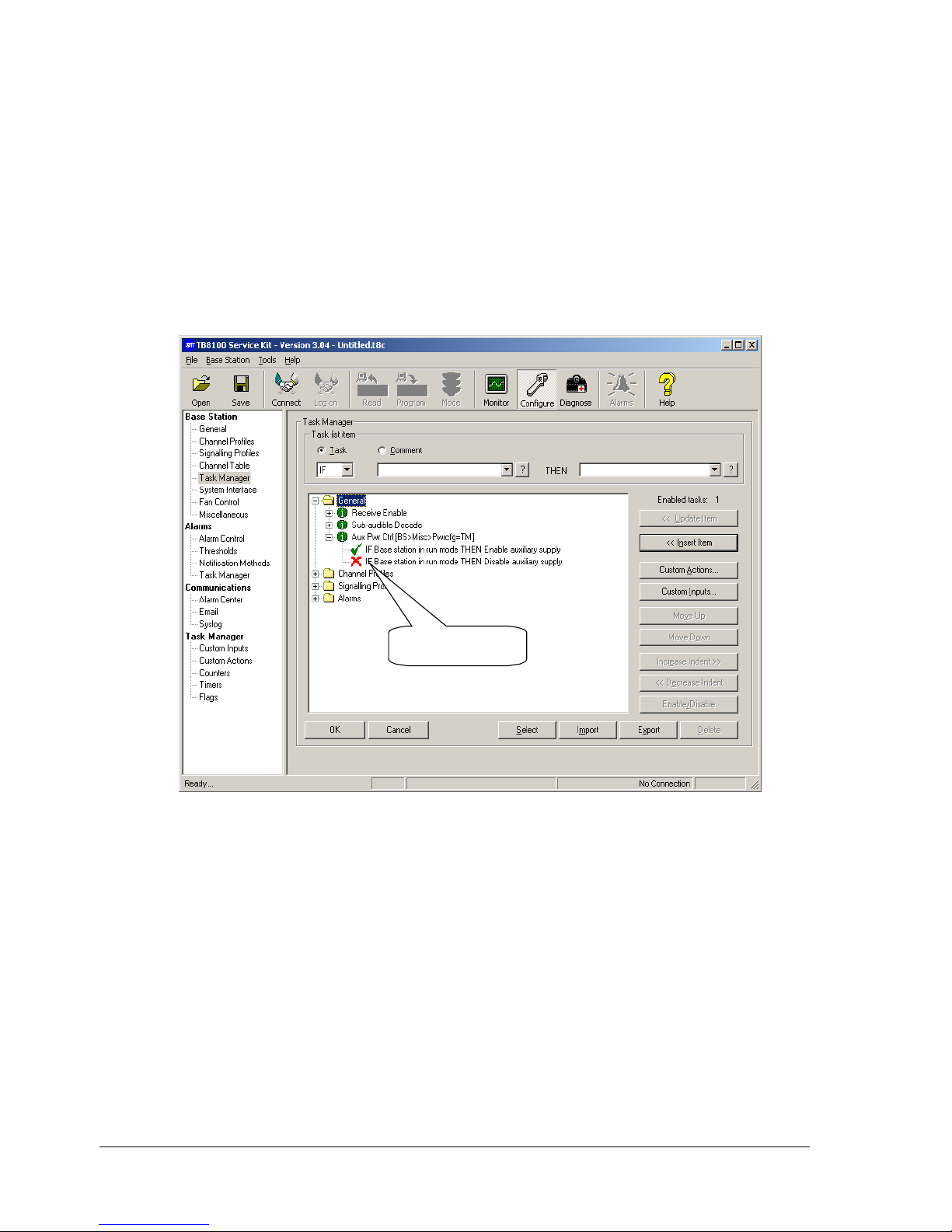
Set up the default channel profile as follows (refer section 5.2):
1. Enable Tx path A.
2. Set the Balanced Line output level to –10 dBm.
3. Enable Rx Path A.
4. Set the Balanced line input level to –10 dBm.
5. Disable Talk through Repeater
6. On the Tone-On-Idle tab, ensure that Tone On Idle is disabled
(Balanced Line Output and Unbalanced Line Output unchecked).
6Set up the T805 Remote Site Unit
This procedure assumes that the
LEM card has been adjusted to
provide the nominal level to line
at the control site (1 kHz tone).
1. Adjust RV201 for a level of 98 mVRMS ±3 mV at “link I/P Testpoint” (pin
6 of J406).
2. Set switch S303-7 to the OFF position.
3. Key the TX
4. Set RF test set filters to provide a 50 to 300 Hz BPF
5. Adjust RV202 for the desired CTCSS deviation ±5Hz.
6. Set switch S303-7 to the ON position.
7. Set switch S303-8 to the OFF position.
8. Set RF test set filters to provide a 300 to 3000 Hz BPF
9. Verify that deviation is 3.0 (1.5) kHz ±0.2 (0.1) kHz
10. If the site is required to operate as a “Talk Through” repeater in the
link fail condition:-
(A) Feed a carrier modulated at the nominal system level into the
receiver of the base station at an RF level of –70 dBm.
(B) Configure TR1 on the RSU for the desired timeout period (refer to
T805-26 manual)
(C) Remove the link input connector from J414 (RJ11).
(D) Allow timer TR1 to time out.
(E) Adjust RV200 to achieve the same level of deviation as measured
in (9) above.
11. Set switch S303-8 to the ON position.
12. If Line Fail Talk Through is not required, set timer TR1 to zero (tr1,0)
7Position and Layout of Equipment
During operation, the TB8100 base station can become hot. This is normal
since it is designed to operate at high temperatures. (The power amplifier
(PA) fan turns on when the PA temperature reaches 60° Celsius, this is
adjustable via Configure>Basestation>Fancontrol)
Consequently, any equipment placed directly above the TB8100 base
station will also become hot. It is therefore important that the layout and
position of equipment is carefully considered.

Tait Confidential Tait Electronics Ltd
Telephone:+64-3-357-9991 TN-1013-AN
http://support.taitworld.com Date of Print: 12/03/07 Page 9 of 9
8Issuing Authority
Name and Position
of Issuing Officer
Jeff Northcott
Senior Technical Support Engineer
Confidentiality Confidential – This message or document contains proprietary information
intended only for the person(s) or organisation(s) to whom it is addressed.
All Recipients are legally obliged to not disclose Tait technological or
business information to any persons or organisations without the written
permission of Tait.
Distribution Level Associate, Associate System Integrator, Accredited Service Centre,
Accredited Service Centre System Integrator and Tait Only
Document History Original Release 9 March 2007 JN
Other manuals for TB8100
12
Table of contents
Other Tait Accessories manuals