Dynalabs DYN-C-1000-LN User manual

Model DYN-C-1000-LN
2g/5g/10g/30g/50g/100g/200g
Product Manual

All rights reserved. Reproduction or issue to third parties in any form whatsoever is not permitted without written authority from the proprietors.
2
Product Support
If at any time you have questions or problems with the DYN-C-1000-LN
sensors, please contact a Dynalabs engineer at:
Phone: +90 312 266 33 34 (9 a.m. to 5 p.m., UTC +3)
Warranty
Our products are warranted against defective materials and workmanship for one
year. Defects arising from user errors are not covered by the warranty.
Copyright
All copyrights of this manual belonging to Dynalabs products are reserved. It
cannot be reproduced without written consent.
Disclaimer
Dynalabs Ltd. provides this publication "as is" without warranty of any kind,
express or implied, including but not limited to, the implied warranties of
merchantability or fitness for a particular purpose. This document is subject to
change without notice, and should not be construed as a commitment or
representation by Dynalabs Ltd.
This publication may contain inaccuracies or typographical errors. Dynalabs Ltd.
will periodically update the material for inclusion in new editions. Changes and
improvements to the product described in this manual may be made at any time.

All rights reserved. Reproduction or issue to third parties in any form whatsoever is not permitted without written authority from the proprietors.
3
Table of Contents
1) Introduction..........................................................................................................................................4
2) General Information.............................................................................................................................4
2.1) Unpacking and Inspection.............................................................................................................4
2.2) System Components......................................................................................................................4
2.3) Specifications................................................................................................................................5
2.4) Outline Drawing............................................................................................................................6
3) Operation and Installation....................................................................................................................7
3.1) General..........................................................................................................................................7
4) Sensor Static Calibration Verification .................................................................................................7
5) Declaration of Conformity...................................................................................................................8

All rights reserved. Reproduction or issue to third parties in any form whatsoever is not permitted without written authority from the proprietors.
4
1)Introduction
Capacitive accelerometers are based on proven micro-electro-mechanical systems
(MEMS) technology. These capacitive accelerometers are reliable and long-term
stable. These sensors are Differential Ended type DC response sensors. The
advantages of these sensors are their outstanding temperature stability, external
noise immunity and their lightweight. These sensors feature standard reliable
aluminum housing with protection class IP68. Steel housing is also possible.
Dynalabs LN accelerometers provide Low noise –high resolution with an
outstanding noise performance from 9 to 680 μg/√Hz. These accelerometers
provide a wide frequency range (±5%) from 250 Hz to 1,500 Hz.
DYN-C-1000-LN sensors offer the following options;
• Custom Cable Length
• Custom Housing Material
• Custom Connector
• Base plate
2) General Information
2.1) Unpacking and Inspection
Dynalabs products provide adequate protection for undamaged products to be
transported. Document the damages that occur indirectly during the transport
and contact the customer representative.
2.2) System Components
The DYN-C-1000-LN has the following components:
-MEMS Sensor
- Calibration Certificate
-Product Manual

All rights reserved. Reproduction or issue to third parties in any form whatsoever is not permitted without written authority from the proprietors.
5
2.3) Specifications
Table 1: Specifications datasheet
1002LN
1005LN
1010LN
1030LN
1050LN
1100LN
1200LN
Full scale
acceceleration
(g)
±2
±5
±10
±30
±50
±100
±200
Sensitivity
(mV/
g)
1,350
540
270
90
54
27
13.5
Frequency
range (±5%)
(Hz)
700
1,150
2,000
2,300
2,700
2,900
2,500
Non-linearity
(full scale)
(%)
0.15
0.15
0.15
0.15
0.15
0.15
0.15
Noise (in band)
(μg/
√Hz)
9
21
40
100
180
340
680
Bias
temperature
(mg/
°C)
±0.2
± 0.5
± 1
± 3
± 5
± 10
± 20
Shock
survivability
(g)
2,500
2,500
2,500
3,000
3,000
3,000
3,000
Environmental
Table 2: Environmental Specifications datasheet
Protection Level
IP 68
Operating Voltage
5 V –20 V
Operating Temperature
-40 °C to +100 °C
Operating Current Consumption mA
7 mA
Isolation
Case isolated

All rights reserved. Reproduction or issue to third parties in any form whatsoever is not permitted without written authority from the proprietors.
6
Physical
Table 3: Physical Specifications datasheet
Sensing Element
MEMS Capacitive
Housing Material
Aluminum or Steel
Connector (Optional)
D-Sub 9 or 15 pin, Lemo, Binder
Mounting
Adhesive or screw mount
Base plate (Optional)
Aluminum or Steel
Weight (without cable)
10 g (aluminum)
20 g (steel)
2.4) Outline Drawing
The dimensional properties of DYN-C-1000-LN sensors are given below;

All rights reserved. Reproduction or issue to third parties in any form whatsoever is not permitted without written authority from the proprietors.
7
3) Operation and Installation
3.1) General
The general sensor connector configuration is given below;
Cable Code/Pin Configuration:
• Red : V + Power supply voltage +5 to +20 VDC
• Black : Ground Power GND
• X : Yellow : Signal(+) Positive, analog output voltage signal for differential mode.
Blue : Signal(-) Negative, analog output voltage signal for differential mode.
WARNING
Never connect the power supply and/or the power ground to yellow and/or blue
cables.
Never connect the power supply to the power ground. Always use a clean power
source and check the voltage range.
4) Sensor Static Calibration Verification
Using gravity, voltage values are measured in the + and –gravity directions, providing a value
of ±1 g. The measurement should be made as follows;
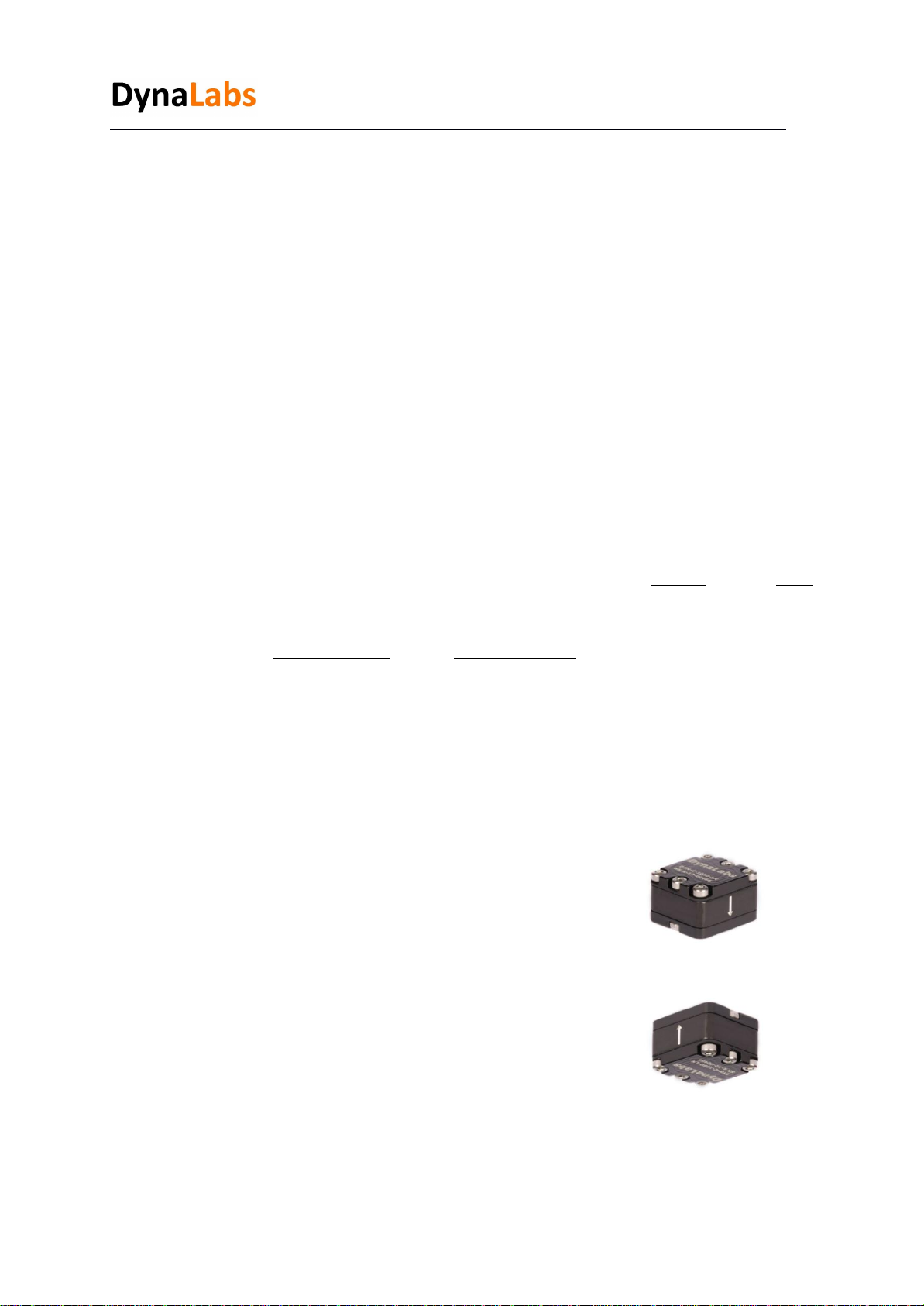
When the sensitivity value of 1000LN series sensors is used
with the data acquisition system, the sensor shows +1 g
with the effect of gravity in the direction of the arrow sign.
When the sensor is in the opposite direction of the arrow,
it shows -1 g with the effect of gravity.
Using gravity, the voltage values that provide 1 g in the + and - directions are measured and
compared with the catalog value. The calibration value should be close to the catalog value with
10% tolerance. Sensor catalog sensitivity values are given in Table 1.

All rights reserved. Reproduction or issue to third parties in any form whatsoever is not permitted without written authority from the proprietors.
8
5) Declaration of Conformity
This declaration of conformity is issued under the sole responsibility of the manufacturer.
The product(s) are developed, produced and tested according to following EC- directives:
•2014/35/EU –Low Voltage Directive (LVD)
•2006/42/EU –Machinery Safety Directive
•2015/863/EU –RoHS Directive
Applied standards:
• EN 61010-1:2010
• EN ISO 12100:2010
• MIL-STD-810-H-2019 (Test Methods: 501.7 - High Temperature, 502.7 - Low
Temperature, 514.8 - Vibration, 516.8 –Shock)
DYNALABS MÜHENDİSLİK SANAYİ TİCARET LİMİTED ŞİRKETİ declares
that above mentioned products meet all the requirements of the above mentioned
standards and regulations.
Murat Aykan, Technical Manager
Ankara, 15.07.2021
This manual suits for next models
7
Table of contents
Other Dynalabs Accessories manuals