Salvis Cucina Evo Easy Series User manual

SALVIS Combi-Steamer CucinaEVO Easy
CucinaEVO Pro
Installation instructions
en: Translation of the Original Installation Instructions
Please read the installation and operating instructions before installing and starting to use the appliance!
Gas appliances
611 621 1011 1021 QT
2011 2021 QT

Table of contents page
2/ 28
1. User information 3..............................................................
1.1 Information about the instructions for the appliance 3. . . . . . . . . . . . . . . . . . . . . . . . . .
1.2 Symbols in front of the text 3. . . . . . . . . . . . . . . . . . . . . . . . . . . . . . . . . . . . . . . . . . . . . . .
1.3 Warning signs, danger symbols and information symbols 3. . . . . . . . . . . . . . . . . . . . .
1.4 Documenting the type plate data 4. . . . . . . . . . . . . . . . . . . . . . . . . . . . . . . . . . . . . . . . . .
2. Safety instructions 4. . . . . . . . . . . . . . . . . . . . . . . . . . . . . . . . . . . . . . . . . . . . . . . . . . . . . . . . . . . .
2.1 Gas appliances safety notes 5. . . . . . . . . . . . . . . . . . . . . . . . . . . . . . . . . . . . . . . . . . . . . .
3. Transport, Setup 6. . . . . . . . . . . . . . . . . . . . . . . . . . . . . . . . . . . . . . . . . . . . . . . . . . . . . . . . . . . . . .
3.1 Inspection for transport damages 6. . . . . . . . . . . . . . . . . . . . . . . . . . . . . . . . . . . . . . . . . .
3.2 Transport 6. . . . . . . . . . . . . . . . . . . . . . . . . . . . . . . . . . . . . . . . . . . . . . . . . . . . . . . . . . . . . .
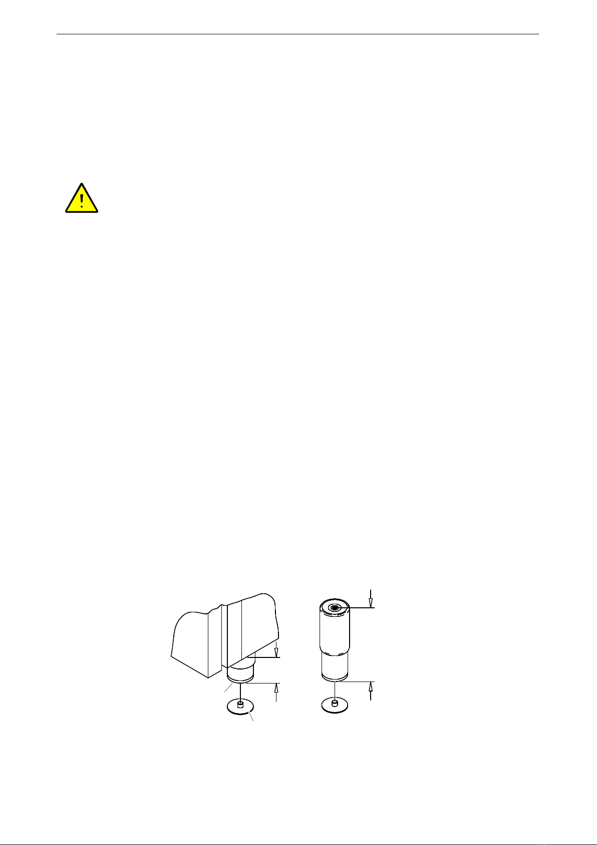
3.3 Setup 6. . . . . . . . . . . . . . . . . . . . . . . . . . . . . . . . . . . . . . . . . . . . . . . . . . . . . . . . . . . . . . . . . .
3.3.1 Observe the setup regulations 6.............................................
3.3.2 Choosing the setup location 7...............................................
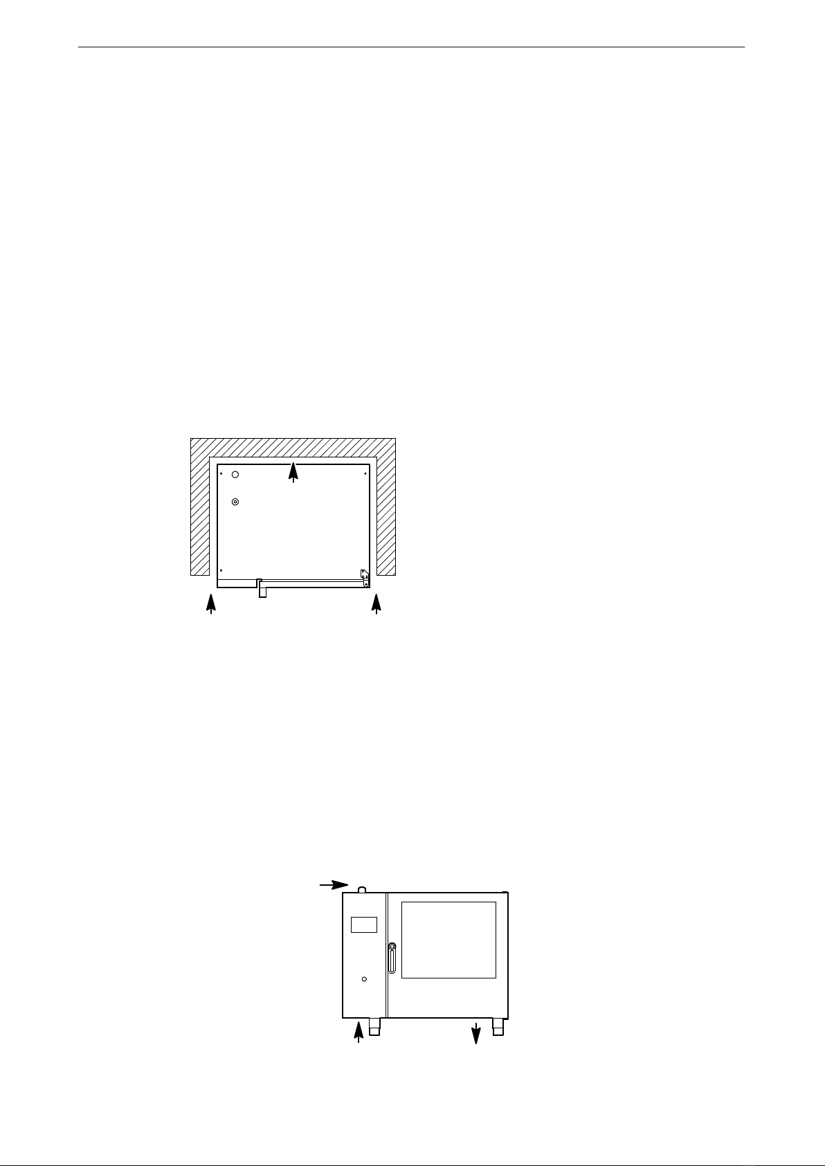
3.3.3 Maintain clearances 7......................................................
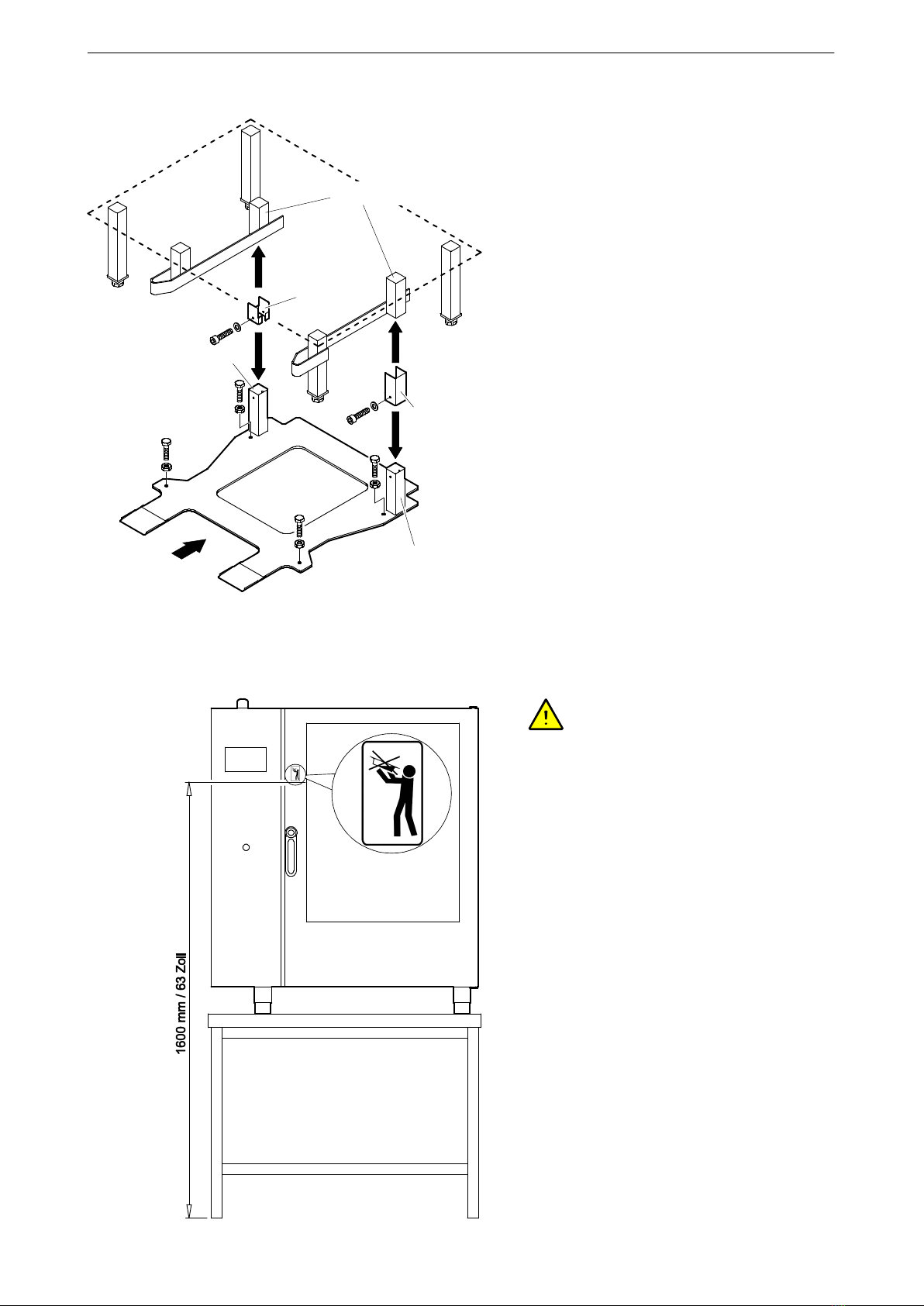
3.3.4 Setup on tables and support structures 8.....................................
3.3.6 Setup of the upright appliances, e.g. Type 2011 9..............................
3.3.7 Installing the compensation frame for Type 2011/2021 (option) 10.................
3.3.8 Apply the safety sticker ”Max. shelf level for liquid cooking products” 10. . . . . . . . . . . .
3.3.9 Appliance on wheels (option) 11..............................................
4. Water connection 11. . . . . . . . . . . . . . . . . . . . . . . . . . . . . . . . . . . . . . . . . . . . . . . . . . . . . . . . . . . . .
4.1 Information for water connection 11. . . . . . . . . . . . . . . . . . . . . . . . . . . . . . . . . . . . . . . . . . .
4.2 Choice of water softening device / water filter / water treatment 12. . . . . . . . . . . . . . . .
4.2.1 Water treatment systems 12.................................................
4.2.2 Do not use these systems. 12................................................
4.2.3 Water hardness conversion table by country 12.................................
4.2.4 Requirements on the soft- and cold-water connection 13.........................
4.3 Connection of soft- and cold water 14. . . . . . . . . . . . . . . . . . . . . . . . . . . . . . . . . . . . . . . . .
5. Connecting water drainage – connection examples 15................................
6. Electrical connection 16..........................................................
7. Initial commissioning 17..........................................................
8. Setting up, connecting gas appliances 18...........................................
8.1 Feed combustion air, extract exhaust gases 18. . . . . . . . . . . . . . . . . . . . . . . . . . . . . . . .
8.1.1 Gas appliance Type A3 (≤ 14 kW) 18.........................................
8.1.2 Gas appliance Type A3 (> 14 kW) 19.........................................
8.1.3 Gas appliance Type B13BS, connection to a chimney 19........................
8.2 Appliance category K (I2K) Netherlands 20. . . . . . . . . . . . . . . . . . . . . . . . . . . . . . . . . . . .
8.3 Connection pressure 20. . . . . . . . . . . . . . . . . . . . . . . . . . . . . . . . . . . . . . . . . . . . . . . . . . . . .
8.4 Consumptions (1023.25 mbar - 15°C) 20. . . . . . . . . . . . . . . . . . . . . . . . . . . . . . . . . . . . .
8.5 Combustion air, exhaust gas volume 20. . . . . . . . . . . . . . . . . . . . . . . . . . . . . . . . . . . . . . .
8.6 CO, CO2 emissions 21. . . . . . . . . . . . . . . . . . . . . . . . . . . . . . . . . . . . . . . . . . . . . . . . . . . . .
8.7 Connect gas supply, check gas pressures 21. . . . . . . . . . . . . . . . . . . . . . . . . . . . . . . . . .
8.7.1 Connect gas supply 21. . . . . . . . . . . . . . . . . . . . . . . . . . . . . . . . . . . . . . . . . . . . . . . . . . . . . .
8.7.2 Check flow pressure, output pressure 22......................................
8.8 Exhaust gas analysis/setting exhaust gas values (CO2) 23. . . . . . . . . . . . . . . . . . . . . .
9. Dimensions, connections, technical data 24.........................................
9.1 Dimensions: 611/621QT, 1011/1021QT 24. . . . . . . . . . . . . . . . . . . . . . . . . . . . . . . . . . . .
9.2 Connections: 611/621QT, 1011/1021QT 25. . . . . . . . . . . . . . . . . . . . . . . . . . . . . . . . . . .
9.3 Connections: 2011QT, 2021QT 26. . . . . . . . . . . . . . . . . . . . . . . . . . . . . . . . . . . . . . . . . . .
9.4 Technical specifications 26. . . . . . . . . . . . . . . . . . . . . . . . . . . . . . . . . . . . . . . . . . . . . . . . . .

Installation instructions
3/ 28
1. User information
1.1 Information about the instructions for the appliance
These installation instructions contain technical data, information on transport, setup, installation and ad
justment of the appliance. Hand the installation instructions to the installing assemblers. Make sure that
during the installation of the appliance the installation instructions are followed meticulously. This will pro
tect you and prevent damages to your appliance.
Refer to the operating instructions for information about operating the appliance.
Read the operating- and installation instructions carefully before starting to use the appliance.
The owner of the appliance must ensure that the instructions are accessible to the staff employed to oper
ate the appliance.
Always keep the documents accompanying the appliance close to hand and pass these on with the appli
ance to any new owner.
1.2 Symbols in front of the text
.You are requested to carry out an action.
−Enumeration and listing
DNotes, operational sequences
Text without symbols: Descriptions or explanations after a heading.
Text in italics – refers to another chapter
1.3 Warning signs, danger symbols and information symbols
DANGER! High voltage! Risk of electric shock that may result in serious injury or death!
WARNING! Risk of injury, risk of damage! Warning of possible injury, a health risk or dam
age to property! Wear protective clothing, protective gloves and safety goggles! Exercise
appropriate caution!
Information! Notes containing particularly useful information and tips.
Translation of the original installation instructions

Installation instructions
4/ 28
1.4 Documenting the type plate data
.Enter the type plate data below before setting up
the appliance.
.Please quote these data when you require after-
sales service for the appliance. This will speed up
the response to your questions.
Model:
Year of manufacture:
Serial-number (S.No.):
2. Safety instructions
DNote the safety information in the operating- and installation instructions.
DCaution! Before opening the appliance, switch it off at the mains and safeguard it against being
switched back on.
DWrong electrical- installation can lead to serious injuries or death. Electrical connections may be made
only by an electrical-specialist!
DThe appliance must not be operated if the mains cable/mains plug is damaged. Have the mains cable/
mains plug replaced by authorised Customer Service or a qualified electrician, otherwise there is a risk
of electric shock!
DWear protective gloves to avoid cutting injuries, e.g. from sharp sheet metal edges in the appliance.
DIncorrect setup, settings, modifications or neglected service work on the appliance may cause damage
to the unit or personal injuries.
DThe water supply- and drain connections may be made only be skilled persons or the authorised cus
tomer service!
DThe appliance may not be operated without water connection! Otherwise overheating and cut-out
through the control system.
DDamages caused by ignoring installation instructions are exempt from the warranty.
DDamaged devices must not be connected or used any more!
DThe appliance may no longer be operated when the glazing in the door, on the cooking chamber light
ing or on the control panel is damaged!
DRepair- and service tasks may be performed only by authorised and trained service personnel.
611/621, 1011/1021 QT,
2011/2021 QT
Type plate be
hind the control
panel
Type plate on the
side panel and front

Installation instructions
5/ 28
2.1 Gas appliances safety notes
DANGER! Risk of fire, explosion, suffocation, malfunction, if incorrectly connected or incorrect
changing to other types of gas.
DDo not switch on the appliance if you smell gas in the installation room! Risk of explosion! Immediately
close the gas shut-off device at the building! Do not switch on or off electrical appliances! Open
windows and doors! Thoroughly ventilate the installation room with a draught! Leave the room! Inform
the standby service of the gas grid operator! Determine the location of the gas leak after adequate air
exchange!
DIncorrect installation, maintenance and modifications to the appliance can result in serious injuries or
death!
DThe gas appliance may be connected only by the contract installation company/gas utility company.
DWork on gas consumption facilities in industrial kitchens such as
−switching to another type of gas,
−inspections, services,
−elimination of malfunctions and
−initial commissioning
must only be carried out by
−the gas supplier,
−an experienced representative of the manufacturer,
−by a distribution agency authorised by a large liquefied petroleum gas concern.
DBefore connecting
−make sure to inform the respective gas supplier.
−Check that the type of gas set for the appliance agrees with the type of gas at the installation loca
tion.
DWhen connecting, converting or servicing the gas appliance, make sure to check
−the exhaust gas extraction from the set-up area,
−the fresh air supply to the burning points,
−tightness of the gas-bearing parts (leak spray),
−burning safety and combustion performance,
−ignition, safety and control equipment.
DObserve the country-specific regulations for gas installation!
DObserve the "Technical regulations for liquid gas" (TRF) and "Technical regulations for gas in
stallations" (DVGW-TRGI, G 600, G 631, G 634, G 660, G 670)!
DObserve regulations applicable in Switzerland!
−Swiss Gas and Water Association (SVGW), G1 Standard: Standard for Natural Gas Installations in
Buildings
−SVGW, L1 Guidelines: Guidelines for Residential, Commercial and Industrial Liquefied Gas Installa
tions
−Swiss Federal Coordination Commission for Occupational Safety (FCOS), Standard No. 6517 Stan
dard for Liquefied Gas
−Regulations from cantonal authorities (e.g. from fire safety authorities)
−Regulations from the Cantonal Fire Insurance Association (VKF)
DInstallation work must be carried out in accordance with the manufacturer´s assembly instructions and
in accordance with accepted technical regulations.
DInstallation of individual burner components of makes or types from third parties is not permitted, as
well as so-called gas savers.
DSelect the installation site so that no dust, lint, greases, etc. can be sucked in. If contamination is
sucked in, this may lead to poor combustion with toxic exhaust gases and damage of the gas burner.

Installation instructions
6/ 28
3. Transport, Setup
Additional notes on set-up, connection of gas appliances, see page 18 chapter 8.
3.1 Inspection for transport damages
.Check the packaging and appliance for transport damages.
.If transport damages are suspected, notify your freight carrier or the factory without delay!
3.2 Transport
DIf the appliance must be transported outdoors at freezing temperatures, the water-carrying systems in
the appliance must first be drained by authorised customer service. Otherwise the water in the com
ponents will freeze and damage the appliance.
DAccessories are secured inside the cooking chamber by the factory for transport. If these transport
braces are removed, you should transport the appliance only while emptied and cleared.
.Note the weight of the appliance when transporting it by hand. Use the appropriate number of persons
and suitable aids, such as carrying devices and protective gloves. For dimensions and weight informa
tion, see from page 24, Chapter 9.
.Transport on lift truck only on a pallet. Do not raise the lift truck against the appliance since this may
damage components.
.Secure the appliance against tipping over during transport!
.Remove all protective foils from the appliance before the final setup. Remove residual adhesive with
cleaner's naphtha.
3.3 Setup
DSetup and orientation of the appliances must be performed by authorised customer service!
DTo improve accessibility for service work, we recommend carrying out the water- and electrical connec
tions in a flexible manner.
DThe safety temperature limiter cuts off at freezing temperatures. Once the safety temperature limiter
has been sufficiently warmed again from the room temperature, it activates itself automatically.
DNo casters or wheels may be subsequently installed on the appliance!
DSpecial precautions must be taken when setting up the unit on mobile tables or racks! See page 8
Chapter 3.3.4!
.All cartons, packaging material, documents and accessories need to be removed from the cooking
chamber.
3.3.1 Observe the setup regulations
DPlease observe the local kitchen regulations.
DInstallation work must be carried out in accordance with the manufacturer's installation instructions and
in accordance with accepted technical regulations.
DObserve the work-safety information supplied by the employers' liability insurance association.

Installation instructions
7/ 28
3.3.2 Choosing the setup location
DSet up the appliance safe against frost. The ambient temperature at the installation site may not fall
below freezing. Otherwise the water in the components will freeze and damage the appliance.
DNo heat- or steam sources may be located underneath or next to the appliance.
DThe device must not be able to directly intake cold supply air from outside the building. If the tempera
ture of the air supply is too low, error messages and malfunctions can occur.
DThe environment at the location of installation must always be ventilated and heated in such a manner
that humidity or steam cannot condense in the device. Damages caused by this are not subject to the
manufacturer's warranty obligation.
DDo not set up the appliance next to deep fryers! Water from the pull-out shower must not enter the
deep fryer (observe the safety regulations)!
DSetup under exhaust hoods according to VDI 2052 guidelines (room air systems for kitchens).
DSet up the appliance so that the cooking chamber door cannot hit against any objects when opening it,
such as wall or devices (risk of breakage of glazing).
DDo not set up the appliance directly under sprinkler heads or smoke detectors.
3.3.3 Maintain clearances
DThe clearance of the appliance to the wall at the
left, right and rear must be at least
5 cm / 2 inches.
DOnly with types QT: Because the main service
duties take place at the left side of the appliance,
we recommend maintaining a larger distance at
this side, e. g. greater than 80 cm / 32 inches.
DProvide distances to heat- or steam sources or
install shields to prevent any steam as well as
warm or moist air to enter the appliance. If the
ambient temperature above, below or to the left of
the appliance is too high, this may trip the safety
cut-out of the appliance.
DAllow sufficient manoeuvring space for the operating personnel (hazard from accidentally bumping into
persons)!
DDo not block the supply and exhaust-air openings on the appliance.
DThe environment on the vent pipe for the cooking chamber must be resistant to steam and hot air!
DHot air or steam exists from the exhaust openings. For this reason, do not store any objects, e.g. on
wall shelves, above the appliance.
DNo base or pedestal blinds may be installed on the appliance
Supply air/exhaust air for cooking cham
ber
Supply air - control sys
tem
Exhaust air - control
system
611/621, 1011/1021, 2011/2021 QT
Clearances for type:
T = 5 cm / 2 inches
QT = 5 - 80 cm / 2 - 32 inches
5-10 cm /
2-4 inches
5 cm /
2 inches

Installation instructions
8/ 28
3.3.4 Setup on tables and support structures
DUse only support frames approved by the appliance manufacturer.
DWhen setting up the appliance on countertops and work tables sufficient stability and load capacity
must be observed. Note the weight of the appliance, including the contents. For weight information, see
from page 24, Chapter 9.
DSecure support frames and setup surfaces against tipping.
Safety notes and instructions for use for units on mobile table or rack
.Setting up the unit of mobile tables or racks should be avoided for safety reasons! However, if the cus
tomer requests a mobile design, the following instructions on setup and use must be observed!
DTo protect power cables, secure the mobile table or rack with a safety chain! The safety chain must be
shorter than the power cable! Fasten the safety chain accordingly short.
DThe table or rack must be secured against rolling off during operation! Lock the parking brake at the
wheels! The appliance must not be moved during operation!
DMove mobile tables or racks carrying units only on level surfaces! Do not drive over inclines or steps!
DBefore moving the unit remove vessels/food items from the unit, switch off the room's main switch, pull
the power plug, close the water shut-off tap, remove the water drain pipe and water supply hose, wind
up all supply lines and secure against falling down, disengage the parking brake on the wheels; caution
- danger of tipping: Move the table or rack carrying the unit carefully!
DCheck before each reconnection whether the electrical supply cables and hose connections are not
damaged! The unit must not be started if the supply lines are damaged!
3.3.5 Adjust screw bases, secure the appliance against movement
(type 623, 611/621, 1011/1021)
DSet up the appliance level. Compensate minor unevenness with the adjustable bases. Attention, note
maximum extension dimension!
DSecure the appliance against movement.
Types 611/621, 1011/1021 QT
Locking washer assy. item no. 880654
At least two items required. e.g. bond to the
table top for the front feet.
The setup face of the base
is perforated in the centre.
Punch out the perforation
to place on the locking
disk.
100 to max.
130 mm
Support
base item
no. 881166
120 to max.
180 mm
Standard
Optional

Installation instructions
9/ 28
3.3.6 Setup of the upright appliances, e.g. Type 2011
.Align the appliance horizontally to ensure that
water is optimally drained from the cooking cham
ber.
.Check after aligning the unit whether the door
closing mechanism properly engages with the
door catch.
DRisk of damage If not set correctly, the door clos
ing mechanism may hit the tip of the door catch
and damage it.
.Install washers on the wheel attachments of the
rack trolley to align the trolley flush with the cook
ing chamber.
DThe rack trolley must not brush against the seals
of the cooking chamber, and must have a uniform
distance on all sides.
DThe seal area of the rack trolley must lie flush
against the lower door seal to ensure closure.
.To prevent the appliance from sliding, fasten it
with wall mounting elements or floor fasteners.
.Secure the front screw bases with the foot
clamps against turning.
Door closing
mechanism
Door catch
Wall mount for type
2011/2021 item no.:
882853 (option)
Foot right
rear
Floor fastener, complete, item no.: 882864
(option) - fasten to the floor with double-sided
adhesive tape or, e.g. silicon adhesive
Extend screw base max.
55 mm
Foot bracket
item no. 879943
(option)

Installation instructions
10 / 28
3.3.7 Installing the compensation frame for Type 2011/2021 (option)
The compensation frame is required in order to com
pensate for the unevenness of the ground and to
ensure parallel entry into the cooking chamber.
Up to approx. 25 mm unevenness of the ground can
be compensated.
Kit compensating frame Item No. 881895: Suitable
for 881718 plate rack trolley, 880625 GN rack trolley,
879482 BN rack trolley.
Installing compensating frame
.Use the screw feet and align the appliance hori
zontally
1. Remove the Allen screws from the clamps.
2. Push the clamps downwards over the retaining
tube.
3. Compensation frame not placed beneath the ap
pliance.
4. Push the clamps upwards over the retaining tube.
5. Use an Allen screw to fully tighten the clamps.
6. Horizontally align the compensation frame with
hexagon-headed bolts and lock using hexagon
nuts.
.Check to make sure that the rack trolley can be
moved in parallel to the edge of the cooking
chamber.
3.3.8 Apply the safety sticker ”Max. shelf level for liquid cooking products”
DWARNING! Scald hazard! Containers
with liquids or products to be boiled, becoming
liquid during the cooking process, may only be
pushed into the slot that can be easily viewed by
the operating personnel.
DSlopping may cause scalding when removing li
quid cooked products!
DFor appliance where the top slot for containers is
placed higher than 1.60 m / 63 inches, the sticker
”Max. shelf level for containers with liquid” must
be affixed.
.Affix the sticker at a level of 1.60 m / 63 inches.
Clean the area where the sticker will be affixed
before applying t.
Clamp, left
Clamp,
right
Retaining tube
Square tube
Square tube
1./5.
1./5.
2.
2.
3.
4.
4.
5.
5.

Installation instructions
11 / 28
3.3.9 Appliance on wheels (option)
DFor appliances on wheels the manoeuvrability of
the appliance must be restricted enough to pre
vent any damage to the supply and disposal
lines.
DShorten safety chain enough to prevent it from
sagging at the planned location.
DSecure the appliance again with the safety chain
after transport.
4. Water connection
4.1 Information for water connection
DObtain information from your local water utility company on the water quality, water pressure and water
hardness.
DObserve the regional regulations and the ”Technical Rules for Drinking Water-Installations EN 1717”!
DThe appliance may only be connected to tap water that corresponds to the potable water regulations.
DThere must be no connecting pipes made from galvanized iron or similar material between the water
softening device and the appliance (otherwise risk of rust forming)!
DObserve the installation- and user manuals for the water softener.
Safety chain 1 metre (item
no. 805904)
Snap hook (item no.
805890)
Eyelet by customer
Mounting example
Spacer sleeve (item
no. 881925)

Installation instructions
12 / 28
4.2 Choice of water softening device / water filter / water treatment
4.2.1 Water treatment systems
DThe manufacturers of water softening devices offer systems provided specifically for hot circulating-air
steamers/combi-steamers. They may also be combined with particle-/fine- and active carbon filters. We
recommend, for example, the water softener from Brita Co.
DDo not connect the water softener to previously softened water.
DReverse- or osmosis-systems may generally constitute an economic alternative to full and/or partial
desalination via filtering systems. Osmosis systems remove nearly all hardness-forming ingredients
and non-hardened minerals from the water. These systems are also required to remove high chloride-
and silicate concentrations.
DParticle-/fine filters with filter grades 5-15 µm filter, for example, contaminations such as deposits from
water pipes, sand, iron particles or suspended matter. Choose sufficient flow capacity of the fine filter to
prevent any pressure loss and to ensure an adequate flow rate.
DActive carbon filters remove excessive chlorine contents.
4.2.2 Do not use these systems.
DSodium ion exchangers (as customary with dish washers) are not permitted for these appliances.
Glazing may become dull and irreparable damage may occur in the cooking chamber.
DSystems with phosphate- and silicate dosing may not be used. They may cause malfunctions in appli
ance parts and deposits in the cooking chamber.
DSystems based on electromagnetic fields do not provide protection against scale formation with this
type of appliance.
4.2.3 Water hardness conversion table by country
Conversion for the units of water hardness
°dH °e°fH ppm mval/l mmol/l
German degrees 1 °dH = 1 1,253 1,78 17,8 0,357 0,1783
British degrees 1 °e = 0,798 1 1,43 14,3 0,285 0,142
French degrees 1 °fH = 0,560 0,702 1 10 0,2 0,1
ppm CaCO3(U.S.) 1 ppm = 0,056 0,07 0,1 1 0,02 0,01
mval/l earthy-base ions 1 mval/l = 2,8 3,51 5 50 1 0,50
mval/l earthy-base ions 1 mmol/l = 5,6 7,02 10,00 100,0 2,00 1

Installation instructions
13 / 28
4.2.4 Requirements on the soft- and cold-water connection
DThe steam generation in the appliances is carried out as fresh steam, that means, the water is directly
introduced into the cooking chamber.
DThe water must conform to the Drinking Water Regulations.
DIn order to prevent damage to the appliance, the following requirements must be observed.
Soft water Cold water
Application For steam generation and automatic
cleaning.
For the steam relief and pull-out
shower
Water temperature Max. 50°CCold water (max. 20°C)
Do not connect to hot water due to
excessive water consumption or poor
function of the steam relief (steam
condensation)!
Min. water pressure 200 kPa = 2 bar (dynamic / flow pressure)
A booster pump must be installed if the water pressure is too low. Check the dy
namic water pressure, e.g. with the pull-out shower opened.
Max. water
pressure
600 kPa = 6 bar (static)
A pressure reducer must be installed if the water pressure is too high.
Water hardness
°dH
Total hardness maximal 5°dH
(0.89 mmol/l)
Total hardness maximal 10°dH
(1.783 mmol/l)
Carbonate
hardness
°dH
Max. 2°dH -
Sulphate
SO4
Install a reverse osmosis system
above 10 mg/l; otherwise there is a
risk of damage from glazing corro
sion.
-
Chlorine /Chlorine
dioxide content
At a chlorine content above 0.1 mg/l (corresponds to 0.1 ppm) an active carbon
filter needs to be installed.
Chloride Max. 50 mg/l (50 ppm)
Above 50 mg/l (50 ppm) a reverse osmosis system needs to be installed;
otherwise strongly increased risk of corrosion.
Iron Max. 0.1 mg
pH value 5,0 - 8,0
Conductivity
value
Max. conductivity value 200 µS/cm (mi
cro Siemens)
-
Contaminations Install a water filter grade 5-15 µm to remove, e.g. water pipe deposits, sand, iron
particles or suspended matter.

Installation instructions
14 / 28
4.3 Connection of soft- and cold water
Risk of damage The appliance may not be operated without water connection! A water connection is re
quired even if the appliance is only used for baking!
DThe connection requires using a pressure-resis
tant flexible DVGW/SVGW-tested hose with a
diameter of at least 1/2inch and union of 3/4 inch.
Provide a hose of adequate length to allow the
appliance to be moved during service tasks.
DThe appliance are factory-equipped with a soft-
and cold water connection. Use the connecting
piece only if you cannot provide separate water
supplies and the specifications for the cold and
soft-water connections are ensured.
.Rinse through the water pipes in the building sys
tem and supply hoses before connecting.
.According to SVGW: Install a backflow guard be
tween water tap and supply hose, provided by the
customer and easily accessible.
.Connect the appliance to an easily accessible
water stopcock.
DThe supply hose may not be kinked or deformed!
.Check that all connections are watertight.
Connection with connecting piece
The connecting piece may be used only if the water
corresponds to the requirements for soft water.
For requirements on the cold- and soft water connec
tion, see page 13 Chapter 4.2.4
611/621, 1011/1021, 2011/2021 QT
Soft water connectionCold water connection
Dirt screen item No.:
249688 (factory-in
stalled)
Connection piece item
No.: 878801 (cannot be
used for type T )
Water connection
G3/4 inches
Sealing ring (included in
connecting piece)
Check valve item No.:
879082 (factory-in
stalled)
Backflow guard / backflow pre
venter item no.: 886240

Installation instructions
15 / 28
5. Connecting water drainage – connection examples
The water drain of gas appliances is centred under the appliance, see figure on next page 25 Chapter 9.2!
DIt is preferable to use the 1st or 2nd connection
examples. Other connection examples may
cause problems in case of backup in the waste
water system. The manufacturer does not as
sume any liability in case of direct connection to
the waste water system (e.g. 3rd and 4th wall
connection).
DThe waste water system must be designed ac
cording to DIN 1986-100 and DIN EN 12056-1.
DUse steam temperature-resistant and flame-retar
dant drain pipe (HT pipe).
DDo not reduce the pipe diameter.
DThe diameter of the on-site drainage pipe must
be at least 50 mm.
DDo not place open drain funnel and water drain in
substructures or under the unit! Condensate may
form from escaping steam! Escaping steam must
be able to move away unhindered and must not
be able to enter electric appliances!
DThe manufacturer does not assume any liability
for consequential damages due to incorrect con
nection!
DThe slope from the appliance to the waste water
connection must be at least 10%!
.To prevent water pouches from forming in waste
water pipes routed freely of extended distances,
the waste water pipe should be fastened at
shorter distances.
.Fill the siphon with water.
Vent pipe protruding
above top of device
At least 25
cm/10inch
3. Wall connection with on-site siphon and vent pipe
We recommend installing a vent pipe when fitting with an
automatic cleaning system and direct connection.
Installation example - appliance on base unit: Customer-
provided siphon in base unit and ventilation beyond the top
edge of the appliance.
4. Wall mount (not approved in Switzerland)
Attention! This design may cause backup in
the drain and thus spilling over at the emer
gency overflow! With this type of connection
the manufacturer does not assume any lia
bility in the event of a fault (cause of the
fault is customer-related).
Get authorized Customer Service to install
an odour trap in the appliance: Locate and
attach the hose from the drip plate to the
appliance siphon so that it creates an odour
trap.
On-site siphon
Appliance
rear
Appliance
rear
≥ 50 mm
≥ 50 mm
On-site siphon
Appliance
rear
1.Siphon with drain funnel
Open drain funnel
At least 2cm/1inch
Appliance
rear
2.Floor drain with siphon
Recommended for models 2011, 2021 and double
rack designs QT.
≥ 50 mm

Installation instructions
16 / 28
6. Electrical connection
DANGER! Electrical voltage! Risk of electric shock that may result in serious injury or death! Installation,
service and repair tasks may only be carried out by authorised Customer Service.
DIf the appliance was transported in a cold environment, it must be stored at least for two hours in a
warm and dry room before making the electrical connection. This prevents condensation of moisture on
the electrical components and their subsequent damage.
DElectrical connection must be carried out by a qualified electrician-
−according to the applicable VDE 0100 regulations and
−the regulations of the power supply company concerned.
DAn electrical main switch must be installed upstream with easy access. The switch must effectively
disconnect the appliance at all poles from the mains. The contact opening must be at least 3 mm.
DInstruct the owner and the operating personnel where the main switch provided in the kitchen for the
appliance is located so that the appliance may be switched off without danger in the event of hazards
to the user.
DInstall ground fault circuit interrupter for safety reasons.
DComply with the circuit diagram included with the
appliance!
DTable units are supplied with a power cable as
series equipment. If the connecting cables must
be replaced, for example, due to the building
structure, a mains cable of the type H07RNF
according to VDEstandard must be used.
DObserve the data on the type plate when making
the electrical connection.
The appliance must be connected to the
equipotential bonding system (earth connection). Its
efficiency must be checked in accordance with
VDE0190.
Electrical supply cable
611/621, 1011/1021, 2011/2021 QT
Equipotential bonding

Installation instructions
17 / 28
7. Initial commissioning
.Remove cartons, foils, accessories, grilles and containers from the cooking chamber.
.Clean outside of the appliance.
.Clean the cooking chamber.
DIf a heating process is not possible after transport in cold environments: The safety temperature limiter
cuts off at freezing temperatures. Once the safety temperature limiter has been sufficiently warmed
again from the room temperature, it activates itself automatically.
.Before initial commissioning or after extended operating breaks, fill approx. 5 litres of water into the
cooking compartment drain (overheating protection/(odour trap).
Only for appliances with automatic cleaning system, not for Types 2011:
.Before initial commissioning or after extended operating breaks, fill approx. 5 litres of water into the
cooking chamber drain (overheating protection/odour trap).
DIf no water is filled (fault number 4003), this results in destruction of the pumps in the drain system!
Description of cleaning process, see chapter in the operating instructions:
−Connection of the cleaning- and rinse-aid canisters for automatic cleaning (optional)
−Cleaning the appliance and the cooking chamber
Gas appliances
Check gas pressures before initial commissioning of gas appliance, see page 22 chapter 8.7.2
Adjusting screen sensitivity, calibrating/aligning the display field
The screen sensitivity adjustment function is used to set sensitivity to touch.
During the calibration process, key assignments are reset/realigned on the screen.
.1.) Carry out screen sensitivity adjustment (Touch Auto Zero).
.2.) Carry out calibration process (Calibrate Touch).
The processes for sensitivity adjustment and calibrating the screen can be found in the operating instruc
tions.

Installation instructions
18 / 28
8. Setting up, connecting gas appliances
This chapter contains special information about gas appliances. Observe also the notes for installation and
connection in the chapters 3. up to 7.!
8.1 Feed combustion air, extract exhaust gases
Gas appliances generate toxic combustion products (CO, CO2). Gas appliances may therefore be ope
rated only in adequately ventilated rooms. Supply and exhaust gases must be supplied and/or extracted in
accordance with the appliance rating.
Observe the country-specific regulations and standards for installation, supply of combustion air and ex
haust gas extraction!
The gas installer/authorised district master chimney sweep calculates the supply of combustion air and
exhaust gas extraction required.
Overview of gas appliance types
Type A
Gas appliance not equipped for connection to a chimney or exhaust gas system from the installation room.
Type B
Gas appliance intended for connection to a chimney to extract the exhaust gases from the installation
room. The combustion air is taken directly from the installation room.
8.1.1 Gas appliance Type A3(≤ 14 kW)
DEnsure locally adequate combustion air supply
and exhaust gas extraction to prevent increased
concentration of hazardous harmful exhaust ga
ses.
DDistance from outlet opening to the exhaust hood
50cm/ 20inch.
Example: Installation under an extraction hood
> 50 cm/20inch

Installation instructions
19 / 28
8.1.2 Gas appliance Type A3(> 14 kW)
DObserve the special regulations and standards
regarding supply air, room capacity, exhaust air,
etc.
DThe distance from the outlet opening of the app
liance to the exhaust air or ventilation ceiling must
be at least 50cm / 20inch.
DAccording to the total nominal load (≥14kW) a
customer-provided “exhaust gas monitoring de
vice” is required. The customer-provided monito
ring device shuts off the gas supply if the exhaust
system does not exhaust.
DWe recommend using flow protection if the gas
appliance is equipped with an upcurrent section.
The flow protection device prevents the develop
ment of a vacuum or excess pressure in the gas
burner and thus of disturbance variables.
DThe distance from the end of the upcurrent sec
tion to the exhaust hood or ventilation ceiling
must be at least 20cm / 8inch.
DThe upcurrent section and flow protection are not
included in the scope of delivery of the appliance
(optionally available).
8.1.3 Gas appliance Type B13BS, connection to a chimney
DObserve the special regulations and standards
regarding supply air, room capacity, exhaust air,
etc.
DWhen connected to a chimney a flow protection
and “thermal exhaust gas monitoring device”
must be installed. The flow protection device pre
vents the development of a vacuum or excess
pressure in the gas burner and thus of distur
bance variables.
DIf the exhaust gas discharge in the chimney is
impeded and the temperature on the temperature
monitoring device exceeds a specified value, the
gas burner is shut off. The gas burner is only ac
tivated again when the exhaust gases can be
extracted without interference and the tempera
ture on the “thermal exhaust gas monitoring de
vice” drops.
DThe “flow protection” and “thermal exhaust gas
monitoring device” are available as options.
DAttention! The “thermal exhaust gas monitoring
device” must not be modified or disabled! Use
only original spare parts when replacement is
required!
DInstall exhaust gas pipes in accordance with local
regulations.
DUse only exhaust gas pipes withstanding exhaust
gas temperatures above 500°Celsius. For exam
ple, do not use aluminium or plastic pipes!
Example: Installation under an exhaust hood
or ventilation ceiling
−with or without upcurrent section
−with or without flow protection
Upcurrent
section
Flow protec
tion
Customer-provided exhaust gas monitoring
device
> 20 cm / 8 inch
> 50 cm / 20 inch
Connection to a chimney
−with flow protection
−with “thermal exhaust gas monitoring de
vice” on the appliance
Chimney connection
Flow protection
Thermal exhaust gas
monitoring device

Installation instructions
20 / 28
8.2 Appliance category K (I2K) Netherlands
This appliance has been adjusted for the appliance category K (I2K) and is suitable for use with G and G+
distribution gases in accordance with the specifications set outin NTA 8837:2012 Annex D with a Wobbe
index of 43.46 - 45.3 MJ/m3 (dry, 0°C, upper value) or 41.23 - 42.98 (dry, 15°C, upper value).
This appliance may also be converted and/or readjusted for the appliance category E (I2E).
The appliance is therefore: “suitable for G+gas and H gas, or demonstrably suitable for G+gas and may
demonstrably be made suitable for H gas” as specified in the “Dutch Decree of 10 May 2016 amending the
Dutch Gas Appliances Decree . . .”
8.3 Connection pressure
No adjustments regarding gas pressures need to be made on the burner system.
The gas components are dimensioned for a maximum gas flow pressure of 60mbar.
A gas pressure controller must be installed on site if gas pressures are greater than 60mbar. If the gas
pressure is lower than the required pressure for the type of gas, the gas supply utility must be contacted.
The integrated gas control valve automatically reduces excess flow pressure up to 60 mbar.
Type of gas Connection pressure (nominal
rating)
Required connection, flow pressure
G20 (2E) 20 mbar 17-25 mbar
G25/25.3 (2L/LL/EK) 25 mbar 18-25 mbar
G30/G31 (3B/P) 28-30 mbar 20-35 mbar
G30/G31 (3B/P) 37 mbar 25-45 mbar
G30/G31 (3B/P) 50 mbar 42.5-57.5 mbar
8.4 Consumptions (1023.25 mbar - 15°C)
Device
model
Output kW Natural gas con
sumption E/H
Propane liquid gas
consumption
Propane liquid gas
consumption
611
min. 9 0.95 m3/h 0.70 kg/h 0.37 m3/h
max. 13.8 1.46 m3/h 1.07 kg/h 0.56 m3/h
621
min. 9 0.95 m3/h 0.70 kg/h 0.37 m3/h
max. 22 2.33 m3/h 1.71 kg/h 0.90 m3/h
1011
min. 10 1.06 m3/h 0.78 kg/h 0.41 m3/h
max. 22 2.33 m3/h 1.71 kg/h 0.90 m3/h
1021
min. 14 1.48 m3/h 1.09 kg/h 0.57 m3/h
max. 30 3.17 m3/h 2.33 kg/h 1.23 m3/h
2011
min. 20 2.12 m3/h 1.55 kg/h 0.82 m3/h
max. 44 4.66 m3/h 3.42 kg/h 1.80 m3/h
2021
min. 28 2.96 m3/h 2.18 kg/h 1.15 m3/h
max. 60 6.35 m3/h 4.66 kg/h 2.45 m3/h
8.5 Combustion air, exhaust gas volume
Combustion air at lambda (λ) = 2 19.04 m3/m3Natural gas 61.90 m3/m3Liquid gas
Exhaust gas volume 10.52 m3/m3Natural gas 33.45 m3/m3Liquid gas
This manual suits for next models
7
Table of contents
Other Salvis Kitchen Appliance manuals

Salvis
Salvis ProfiLine Griddle plate 600 User manual

Salvis
Salvis Evolino Pro User manual

Salvis
Salvis CUCINA EASY User manual

Salvis
Salvis Vitality Pro SDS 1/1-13 User guide

Salvis
Salvis FS 1/1 P User manual

Salvis
Salvis Evolino II User manual

Salvis
Salvis VitalityEVO-Pro User manual

Salvis
Salvis CucinaEVO 623T User manual