PTI SENTRY Supervisor Owner's manual

Installation, Operation and
Serial Communication Programmer’s Guide
SENTRY™Supervisor
Section 1: General Information & Part Descriptions
12279 Rev 1.0 Page 1of 3
1.1General Information
About This Manual
This manual is intended for those responsible for programming a computer or tool to
operate with the SENTRY process exhaust control system through the use of serial
communications. Although this manual may contain additional information not
included in the controller manuals, the complete instructions for installing and
operating a SENTRY system may be found in the controller’s (i.e. SENTRY 1000,
SENTRY 1510, etc.) installation and operation manual.
Note:
• Diagrams included in this manual depict the “CE” version. With exception to
connector styles, both “CE” and “non-CE” versions are installed, operated and
programmed in the same manner. There are no functional differences between
the two versions.
This manual describes the following:
• Physical Installation (Supervisor Only)
• Commonly Used Command Menu Parameters
• Operation in Manual, Analog and Serial Communication Modes
• Required Programming for Using Serial Communication
Description
The SENTRY Supervisor is a microprocessor-based interface used in conjunction
with many of Progressive Technologies' process exhaust controllers. The SENTRY
Supervisor allows the user to communicate electronically with the process exhaust
controller (such as the SENTRY 1000) for changing the set point and reading actual
process exhaust values. It can be configured at the PTI factory to be used with
controllers that maintain constant pressure or constant flow. It can be operated in
stand-alone mode (manual mode), with a 0-5 Volt process tool interfaced analog
signal (analog mode) or with process tool/facility computer interfaced serial
communications (serial mode).
12279 Rev 1.0 Page 2of 3
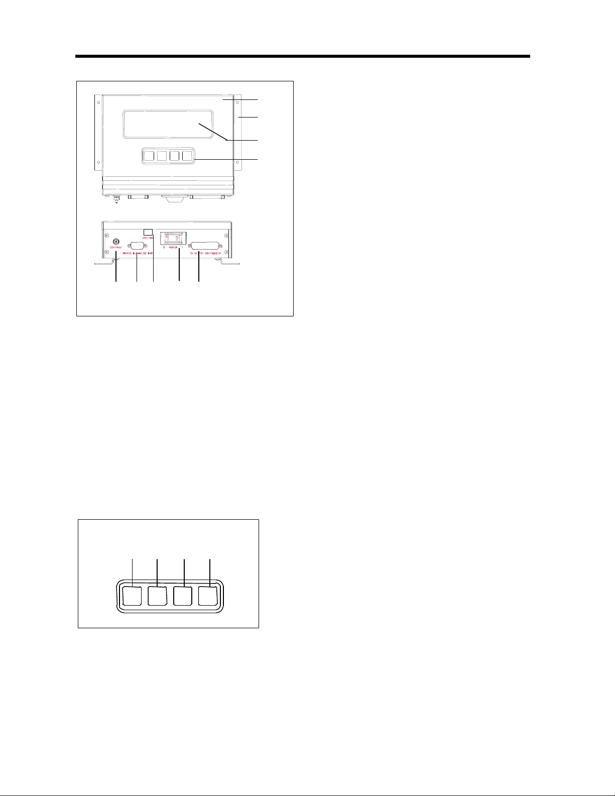
1.2 Part Descriptions
Part Names –Supervisor
ŒŒ SENTRY Supervisor The SENTRY
Supervisor is a microprocessor-based
interface used in conjunction with the
SENTRY exhaust controllers (SENTRY
1000, 1510, and 9000). The SENTRY
Supervisor provides the user with the
ability to interface with the SENTRY
controller through direct manual input
from the user or through electronic
communication from the process tool.
•• Mounting Brackets The brackets are
used to mount the Supervisor to the
process tool.
ŽŽ Display The display provides a real
time read-back of pressure control. It also
allows the user to view and change the
menu parameters.
•• Keypad The keypad contains the
four keys used to navigate and change
the menu tree and parameters.
•• Contrast Knob The contrast knob
allows the user to adjust the display
contrast.
‘‘ Power/Interface Port The port
accepts the power cable or power and
interface cable.
’’ 422/485 Port The port accepts the
serial communication cable.
.““ On/Off Switch The switch is an
on/off rocker with a circuit breaker. The
switch acts as a safety cut-off device
and detects over-current situations and
cuts power to the Supervisor.
”” SENTRY Port The port accepts the
Supervisor to SENTRY controller
cable.
Part Names –Key Pad
ŒŒ Star Key [*] The star key enables a menu
item to be modified when the star key is
depressed on the key pad. A star [*] will appear
in the selection indicator box.
•• Up Arrow [áá] and Down Arrow [ââ] Keys
The arrow keys allow the user to scroll through
the menu items. Once a menu item is chosen
using the star key, the arrow keys provide a
means for selecting a value or option available under the individual menu item.
ŽŽ Enter Key [ENT] The enter key is used to enter into memory the selected menu
item that has been changed. Any change made to a menu item is only activated
after the enter key is pressed.
Ž
•
Œ
•
’
“
•
‘
”
*↑↑ ↓↓ ENT
Œ • Ž •

12279 Rev 1.0 Page 3of 3
1.1 Part Descriptions
Part Names –Display
ŒŒ Selection Indicator A star symbol
“*” will appear in the selection indicator
box when a menu item is chosen by
pressing the star key [*] on the key
pad.
•• Menu Item Name The menu item
name display region indicates the
current menu item available for
modification. The menu is scrollable
through the use of the arrow keys on
the key pad.
ŽŽ Process Exhaust Set Point The
label “Pres S” or “Flow S” indicates
whether the unit is capable of pressure
or flow set point control. The number
indicates the currently active (desired)
set point. Depending on the SENTRY
model, this value will indicate pressure
(“H2O, mm H2O) or flow (CFM). There
may be an implied decimal point.
Refer to the controller manual for
details.
•• Menu Item Value The menu item
value display region indicates the
current set value for the menu item
displayed.
•• Process Exhaust (Actual) Read-
Back The label “Pres” or “Flow ”
indicates whether the read-back is in
units of pressure or flow. The number
indicates the currently achieved
(actual) process exhaust read-back.
Depending on the SENTRY model, this
value will indicate pressure (“H2O, mm
H2O) or flow (CFM). There may be an
implied decimal point. Refer to the
controller manual for details.
‘‘ Graphical Display The graphical
display provides a real-time plot of the
process exhaust read-back.
’’ Full Scale Process Exhaust The
full scale process exhaust indicates the
factory configured full scale range of
the unit being operated. Depending on
the SENTRY model, this value will
indicate pressure (“H2O, mm H2O) or
flow (CFM). There may be an implied
decimal point. Refer to the controller
manual for details.
SS StptMode Single
Pres S 1700 Pres 1713
2000
0
Œ • Ž • • ‘ ’

Installation, Operation and
Serial Communication Programmer’s Guide
SENTRY™Supervisor
Section 2: Installation & Power-Up
12279 Rev 1.0 Page 1of 3
2.1 Installation & Power-Up
The SENTRY Supervisor is only one component of the SENTRY exhaust control
system. Please follow the complete installation instructions for the specific controller
to be installed in the controller manual included with the system.
CE Compliant Installation Note
To maintain CE certification, if applicable, the SENTRY Supervisor must be installed
at a height above the floor greater than 24” (0.6 meter).
Power Requirements
The SENTRY Supervisor operates using both positive and negative DC voltages.
These may be supplied directly from the tool via an interface cable or through a stand-
alone universal power supply available directly from PTI.
The DC supplies required for Supervisor operation are:
1. Positive Voltage: + 15 to +24 VDC @ 500 mA
This voltage is used to power the electronic circuitry of the Supervisor and
controller.
2. Negative Voltage: -15 to -24 VDC @ 50 mA
This voltage is used solely to power the Supervisor display.
Note:
• Only the positive voltage is routed through the Supervisor on/off switch
circuit breaker. The display is powered any time the power cable is
connected to the SENTRY Supervisor.
• When the Supervisor is turned off, the LCD may display random
characters or lines if the power cable is still connected.
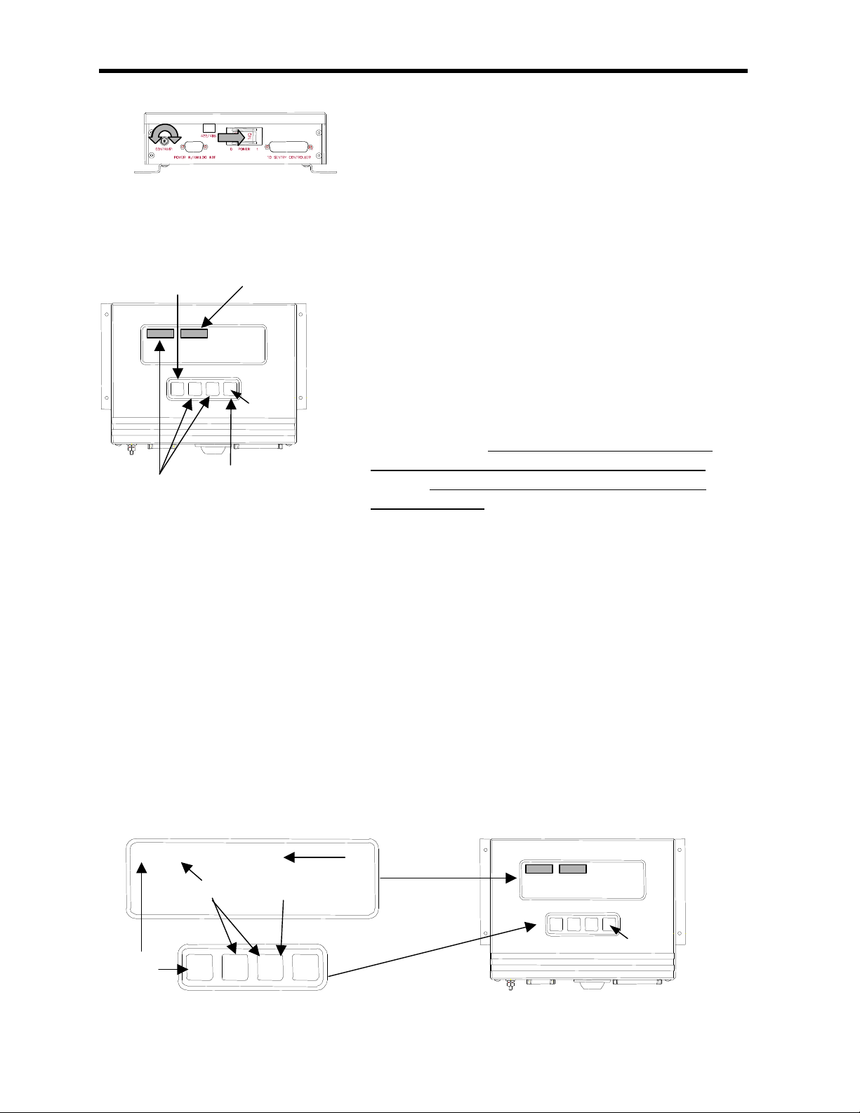
Supervisor Cabling
The SENTRY system is manufactured in CE compliant (“CE”) and non-CE compliant
(“non-CE”) models. Most differences between the two models should be transparent
to the user. However, the two models do not have the same cable connector styles.
The CE compliant model has DB connectors while the non-CE compliant model
maintains the original plastic circular connectors.
Cabling to the Supervisor will depend upon the controller model under installation and
the type of communication interface to be used. Cable drawings for your cable set
have been provided in the drawings section at the end of the controller manual.
Please refer to the controller manual installation and setup section for detailed
instructions on connecting the SENTRY system cabling.
Note:
• In case of over-current situations, the SENTRY system relies upon the tool for
alternating current (AC) disconnect.
12279 Rev 1.0 Page 2of 3
2.1 Installation & Power-Up
Power ON the SENTRY Supervisor
ŒTurn the Supervisor to the ON (1) state.
•Use the contrast knob to adjust the display.
Select Communication Operating Mode
The Supervisor communication operating mode must be selected before set points
can be properly received and interpreted.
ŒUsing the up [á] or down [â] arrow keys on the
SENTRY Supervisor key pad, scroll through the
menu parameters until “STPT MODE” is shown in
the top left corner of the display.
•Choose the menu item by pressing on the star [*]
key.
ŽUsing the up [á] or down [â] arrow keys on the
SENTRY Supervisor key pad, scroll through the
list and choose “SINGLE” if using stand-alone
operation or serial (interface) communication or
choose “ANALOG” if using analog (interface)
communication.
•Press the enter [ENT] key to confirm selection.
Save Operating Parameter Data
Any change made to the menu items is only stored in memory until the power to the
Supervisor is turned off. In order to permanently store selections into memory, the
following steps must be taken.
ŒUsing the up [á] or down [â] arrow keys on the SENTRY Supervisor key
pad, scroll through the menu parameters until “SAVE DATA” is shown in the
top left corner of the display.
•Choose the menu item by pressing on the star [*] key.
ŽPress the down [â] arrow key once (“0” will be displayed).
•Press the up [á] arrow key seven times (“77” will be displayed).
•Press the enter [ENT] key to confirm selection.
Œ
•
Œ
*
↑↑
↓↓
ENT
•
Ž
•
*
↑↑
↓↓
ENT
•
•
Ž
SAVE DATA
77
*
↑↑
↓↓
ENT
Œ
•
*
12279 Rev 1.0 Page 3of 3
2.1 Installation & Power-Up
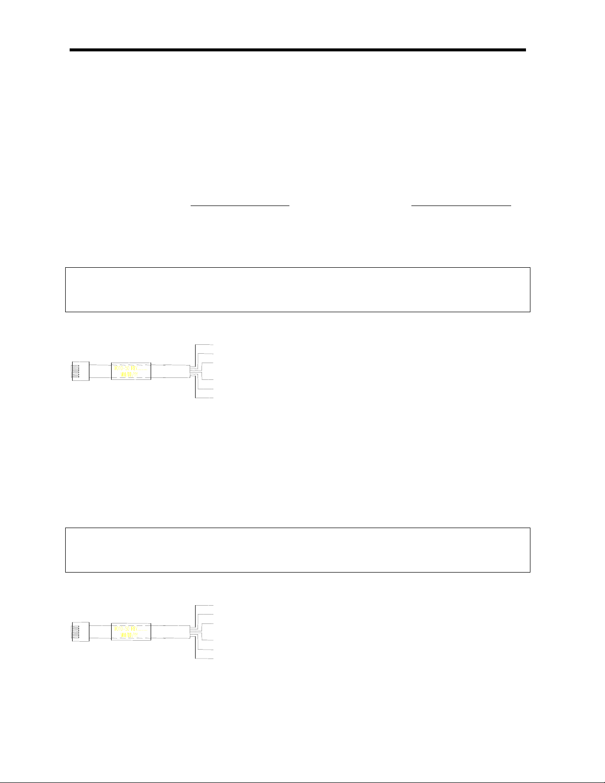
Serial Communication Tool Interface (RS-422 or Optional RS-485)
The SENTRY Supervisor supports an RS422/485 serial communication link for
communication with a process tool or host computer. The Supervisor can be
configured to operate using either a four-wire RS422 link or a two-wire RS485 link.
This is typically factory configured through the use of a jumper on the Supervisor
circuit board. The communication interface is the same regardless of which
communication link is used.
RS-422 Link (Two Differential Pairs)
The RS-422 communication link uses a four wire (Tx+, Tx-, Rx+, Rx-) connection.
Two wires are used to send from the host; two wires are used to receive by the host.
The serial communication interface cable is a six wire cable. The Supervisor end of
the cable is crimped with a RJ-12, 6-pin male connector. The other end is maintained
with labeled flying leads. Please refer to the controller manual for step-by-step
instructions on connecting the serial communication cable to the Supervisor.
Note:
• There are no functional or CE requirements for connecting the two ground leads
and these may be left unattached.
Pin # Function Comment
1Rx+ Receive from host (Positive)
2Rx-Receive from host (Negative)
3gnd Ground –Not Required
4gnd Ground –Not Required
5Tx+ Transmit to host (Positive)
6Tx-Transmit to host (Negative)
RS-485 Link (Single Differential Pair)
The RS-485 communication link uses a two wire (Tx/Rx+, Tx/Rx-) connection. Two
wires are used for bi-directional data transmission. The serial communication
interface cable is a six wire cable. The Supervisor end of the cable is crimped with a
RJ-12, 6-pin male connector. The other end is maintained with labeled flying leads.
Please refer to the controller manual for step-by-step instructions on connecting the
serial communication cable to the Supervisor.
Note:
• There are no functional or CE requirements for connecting the ground lead which
may be left unattached.
Pin # Function Comment
1Tx/Rx+ Bi-directional data (Positive)
2Tx/Rx-Bi-directional data (Negative)
3gnd Ground –Not Required
4-No connection
5-No connection
6-No connection
1 ü
2 ü
3 ý
4 ý
5 ü
6 ü
1 ü
2 ü
3 ý
4 ý
5 ý
6 ý

Installation, Operation and
Serial Communication Programmer’s Guide
SENTRY™Supervisor
Section 3: Command Menu
12279 Rev 1.0 Page 1of 3
3.1 The Command Menu
The SENTRY Supervisor is common to all of the PTI automated exhaust controllers. As such,
the Supervisor contains a number of command items which may not be applicable to the
specific SENTRY system being installed. The complete menu is listed below. The menu
contains 71 individual entries, 64 of which are directly accessible by the keyboard using the
arrow keys. An explanation is provided for the parameters most commonly used. These
menu items are highlighted in the menu list below.
The Complete SENTRY Supervisor Command Menu
1) Sentry Ver 19) Pos Sp2 37) FiltRate 55) PlotMode
2) Pres Sp 20) Pos Sp3 38) Ctrl Inv 56) Plot Sel
3) Flow Sp 21) Pos Sp4 39) Gain 57) Cycle
4) Pos Sp 22) Alarms 40) GainFine 58) CyclItvl
5) Pres 23) Dev Band 41) Integral 59) StptMode
6) Flow 24) Lo Alarm 42) Intg Sum 60) OperMode
7) Step Cnt 25) Hi Alarm 43) Deriv 61) CtrlMode
8) HouseVac 26) Pres FS 44) Deadband 62) ResetAct
9) Aux In 27) Flow FS 45) Hyster 63) Disp #0
10) Pres Sp1 28) House FS 46) MaxCtlSt 64) Disp #1
11) Pres Sp2 29) Aux FS 47) StepRate 65) Disp #2:
12) Pres Sp3 30) SaveData 48) StepRang 66) "Blank":
13) Pres Sp4 31) BaudRate 49) Step Lim 67) Deviation Alarm Flag
14) Flow Sp1 32) Parity 50) Step Req 68) Low Alarm Flag
15) Flow Sp2 33) HWCtlLck 51) Clk Min 69) High Alarm Flag
16) Flow Sp3 34) Ctl Itvl 52) Clk Hour 70) Control In Band
17) Flow Sp4 35) CtrlLock 53) Clk WDay 71) Step Direction
18) Pos Sp1 36) FlowCoef 54) PlotItvl
Explanation of Commonly Used Menu Entries
Ref. # & Menu Item Function
9) Aux In This indicates the measured voltage from the analog input set point control.
This will reflect the voltage received at the SENTRY Supervisor from the tool.
(5000 = 5.000 V).
10) Pres Sp1 For pressure exhaust controllers, this is the entry that allows the pressure set
point to be reviewed or edited. For the SENTRY 1000, 2000 = 2.000” H2O.
For the SENTRY 1510, 2540 = 25.40 mm H2O.

12279 Rev 1.0 Page 2of 3
3.1 Command Menu
Ref. # & Menu Item Function
14) Flow Sp1 For flow exhaust controllers, this is the entry that allows the flow set point to be
reviewed or edited.
26) Pres FS For pressure exhaust controllers, this indicates the full pressure scale for the
exhaust control device. The full scale must match the pressure transducer
inside the control device.
27) Flow FS For flow exhaust controllers, this indicates the full flow scale achievable by the
control device.
29) Aux FS This indicates the full scale of the analog signal input. When using a 0-5 V
control signal (analog interface), this item must be set to 5000, representing
5.000 V full scale.
30) SaveData This is used to save the Supervisor configuration to nonvolatile memory. Refer
to Section 2, page 2. for instructions on saving parameter changes.
31) BaudRate This is used to set the RS422/RS485 serial port speed rate. The process tool
controller or host computer must use the same baud rate. The Supervisor can
handle up to 9600 baud.
32) Parity This item allows the selection of the following serial data parity: Odd, Even,
One, and Zero. After changing parity, Save Data must be executed first and
then power to the Supervisor must be cycled once (On to Off to On).
40) GainFine This indicates the gain (proportional) coefficient that is used in the PID loop
This indicates the same value as the “Gain” menu item but allows the operator
a finer increment of adjustment.
44) Deadband This indicates the band on either side of the set point, within which the process
variable can move and not cause control loop action.
59) StptMode This is used to define where the controller receives its set point. The selections
are: single, analog, dual and quad. Single indicates a single digital set point
from an RS422/RS485 serial connection or manually set by the user. This set
point is the value under Pres Sp1. Analog indicates a remote set point, through
a 0-5 V analog interface. Dual and Quad are not used.
60) OperMode This indicates the process parameter to be controlled. Pressure is indicated by
Pres, flow is indicated by Flow.

12279 Rev 1.0 Page 3of 3
3.1 Command Menu
Scaling Factors
As indicated previously, the SENTRY Supervisor display and menu items do not show a
decimal point. Depending on the SENTRY controller or menu parameter in question, a
decimal point is implied in the displayed value.
SENTRY
Controller Scaling Factor Description
SENTRY 1510 Pressure set point (Pres Sp1), actual pressure read-back (Pres) and
full scalepressure (Pres FS) have an implied decimal point to the left
of the second digit (from the right). A scaling factor of 100 is used.
The implied units are in millimeters of water column.
Example: The displayed value 2540 equals 25.40 mm H2O.
SENTRY 1000 Pressure set point (Pres Sp1), actual pressure read-back (Pres) and
full scale pressure (Pres FS) have an implied decimal point to the left
of the third digit (from the right). A scaling factor of 1000 is used.
The implied units are in inches of water column.
Example: The displayed value 1150 equals 1.150” H2O.
SENTRY 9000 Flow set point (Flow Sp1), actual flow read-back (Flow) and full scale
flow (Flow FS) have an implied decimal point to the right of the first
digit (from the right). No scaling factor is used. The implied units are
in cubic feet per minute.
Example: The displayed value 12 equals 12 CFM.
Modes of Operation
The Supervisor is configured to operate in Pressure Mode (SENTRY 1000 and SENTRY
1510) or Flow Mode (SENTRY 9000) depending on the type of exhaust controller to be
operated. This must be factory configured to match the specific exhaust controller to be
operated. No user configurable options are available for switching between the two modes.
PID Control Loop
The Supervisor contains a PID closed loop algorithm for controlling the SENTRY controller
stepper motor during a set point change. All the SENTRY controllers used in conjunction with
the SENTRY Supervisor have a patented SENTRY piston regulator. The piston regulator
compensates for fluctuations in facility exhaust to maintain a regulated process exhaust. The
highly responsive nature of the SENTRY controller off loads the PID algorithm such that the
algorithm is only required to change the controller set point. Once the new set point is
reached, the SENTRY piston in the controller performs the corrective control.
Note:
• In most applications, only the gain function of the PID loop is used. This is preset at the
factory and does not typically require adjustment.

Installation, Operation and
Serial Communication Programmer’s Guide
SENTRY™Supervisor
Section 4: Operation
12279 Rev 1.0 Page 1of 3
4.1 Operation
Manual Mode (Stand-Alone)
Manual operation of the SENTRY controller is accomplished through the use of the SENTRY
Supervisor key pad. The key pad is used to enter changes to the menu items available within
the Supervisor. Although there are 71 menu entries available, only one, pressure set point
“PRES SP1” or flow set point “FLOW SP1”, is typically used for operation of the SENTRY
controller. The remaining menu items are preset at the factory with settings that should satisfy
the control requirements of most installations. The default factory settings for each SENTRY
controller are listed in the Appendix of the controller manual. A list of the menu parameters
and an explanation of the most commonly used items is included in Section 1.
Using the Key Pad
The keypad contains four keys used to navigate and change the menu list and parameters.
Refer to the key pad description in Section 1. for a list of the key names and their uses.
Note:
• Any change made to a menu item is only activated after the enter key is pressed.
• Any change made to the menu item is only stored in memory until the next time the
Supervisor is powered off and on. To permanently store values in memory, follow
the steps in Section 2, page 2.
Manual Mode Pressure Set Point Changes
Follow the steps below to change the SENTRY 1000 or SENTRY 1510 set point. The Sentry
system is configured to measure and display pressure set points in units of inches of water
column for the SENTRY 1000 and units of millimeters of water column for the SENTRY 1510.
ŒUsing the up [á] or down [â] arrow keys on the SENTRY
Supervisor key pad, scroll through the menu parameters
until “PRES SP1” is shown in the top left corner of the
display.
•Choose the menu item by pressing on the star [*] key.
ŽUsing the up [á] or down [â] arrow keys on
the SENTRY
Supervisor key pad, change the displayed
value to the
desired value.
•Press the enter [ENT] key to confirm selection.
Note:
• For the SENTRY 1000, there is an implied decimal point to the left of the third digit
(2000 = 2.000” H2O).
• For the SENTRY 1510, there is an implied decimal point to the left of the second
digit (2540 = 25.40 mm H2O).
Œ
*
↑↑
↓↓
ENT
•
Ž
•
12279 Rev 1.0 Page 2of 3
*
•
•
Flow Sp1
12
↑↑
↓↓
ENT
Œ
Ž
*
4.1 Operation
Manual Mode Flow Set Point Changes
Follow the steps below to change the SENTRY 9000 set point. The Sentry system is
configured to measure and display flow set points in units of cubic feet per minute.
ŒUsing the up [á] or down [â] arrow keys on the
SENTRY Supervisor key pad, scroll through the
menu parameters until “FLOW SP1” is shown in
the top left corner of the display.
•Choose the menu item by pressing on the
star [*] key.
ŽUsing the up [á] or down [â] arrow keys on the
SENTRY Supervisor key pad, change the
displayed value to the desired value.
•Press the enter [ENT] key to confirm selection.
Note:
• For the SENTRY 9000, a displayed value of 35 = 35 CFM.
Analog Interfaced Operation
When the SENTRY system is configured for analog operation, the process exhaust pressure
or flow set points are entered through the process tool. The analog interface operates on a
standard 0 to 5 volt full scale command signal.
Note:
• The menu item “STPTMODE” must be set to “ANALOG” in order to use analog
communication. Refer to Section 2, page 2. for details.
• The menu item “AUX IN” will reflect the voltage received at the SENTRY Supervisor.
There is an implied decimal point to the left of the third digit (5000 = 5.000 volts).
• The voltage indicated by the “AUX IN” should be within ±.02 volts of the analog voltage
signal transmitted by the process tool.
• Both the analog and power ground leads must be connected to the Supervisor
and be common on the process tool.
The following table illustrates how the set point and read-back analog voltage signals are
interpreted within the Supervisor.

12279 Rev 1.0 Page 3of 3
4.1 Operation
SENTRY 1000, SENTRY 1510 SENTRY 9000
Process exhaust pressure set point:The
set point voltage transmitted from the tool to
the SENTRY Supervisor will be converted to
a pressure set point using the following
equation:
PresSp Aux In
Aux FS PresFS
= ×
Process exhaust pressure read-back:
The read-back voltage returned by the
SENTRY Supervisor to the tool is
proportional to the actual measured pressure
determined by the following equation:
Measured Process Exhaust Pressure =
Pres
Pres FS Aux FS×
Process exhaust flow set point:The
set point voltage transmitted from the tool
to the SENTRY Supervisor will be
converted to a flow set point using the
following equation:
FlowSp AuxIn
AuxFS FlowFS= ×
Process exhaust flow read-back:
The read-back voltage returned by the
SENTRY Supervisor to the tool is
proportional to the actual measured flow
determined by the following equation:
Measured Process Exhaust Flow =
Flow
Flow FS Aux FS×
Serial Interfaced Operation
When the SENTRY system is configured for serial communication operation, the process
exhaust pressure or flow set points are entered through the process tool. The serial interface
operates on standard RS422/485 serial communication protocol. OEM tool or host
programming of interrogation commands is required in order to operate in serial
communication mode. For complete interface instructions, refer to Section 5.
Note:
• The menu item “STPTMODE” must be set to “SINGLE” in order to use serial
communication. Refer to Section 2, page 2. for details.
• The menu items “BAUD RATE” and “PARITY” must reflect the process tool baud rate
and parity in order to use serial communication.

Installation, Operation and
Serial Communication Programmer’s Guide
SENTRY™Supervisor
Section 5: Serial Communication Interface Programming
12279 Rev 1.0 Page 1of 5
5.1 Serial Communication Interface Programming
In order to configure a tool or host computer to communicate with the SENTRY Supervisor
for adjusting a set point or interrogating a read-back value, the tool or computer must be
programmed to communicate with the SENTRY Supervisor. Although it is possible to
address most of the command menu items identified previously, only three commands are
required for serial interfaced communication. The three commands are: power-up clear,
exhaust (pressure or flow) set point and actual exhaust (pressure or flow) read-back
interrogation. This section describes the communication commands, format and protocol
required in order to allow the tool or computer to adjust the set point and report a read-back
through serial communication.
General Description
A message format and communication protocol have been established for transmitting
commands and receiving acknowledgments from the SENTRY Supervisor. The host
processor and the Supervisor have a master and slave relationship, respectively. That is,
the host processor (master) is responsible for initiating communications with the SENTRY
Supervisor (slave). The communication protocol requires the host to send a command to the
Supervisor. For each command sent, the Supervisor will respond with an acknowledgment
message. The communicated commands and acknowledgments are text strings made up of
characters from the ASCII character set.
Note:
• Up to 64 uniquely addressable SENTRY Supervisors can be connected on a given
network.
• Specification guidelines for RS485 provide for a maximum of 32 units, including the
host, on a single network. A repeater is required to add an additional 32 units for a
maximum total of 64 SENTRY Supervisors.
• Refer to Appendix B for the serial communication specifications.
Command Description
The SENTRY Command messages consist of the following components. For a given
command, some or all of the components may be used.
• Start of message character “>”
• Supervisor address and data bank
• Single character command
• Hexadecimal represented data
• Two character checksum
• Carriage return “↵”
Note:
• The SENTRY Supervisor uses the hexadecimal numbering system to represent
numbers in commands and responses. SENTRY command messages are
transmitted as a series of ASCII characters. Numbers are transmitted as the ASCII
number characters 0 through 9 and the upper-case ASCII characters A through F.
• Appendix E provides a decimal to hex and decimal to binary conversion table.
12279 Rev 1.0 Page 2of 5
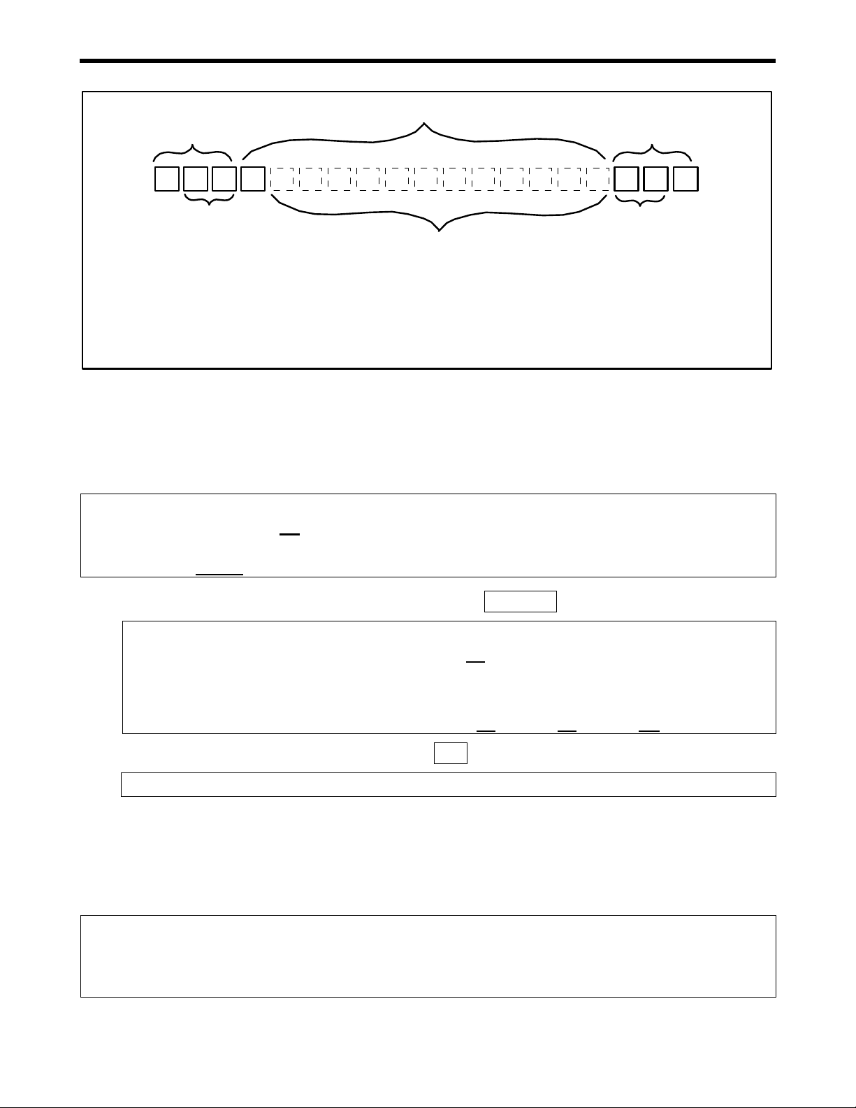
5.1 Serial Communication Interface Programming
Start of message
Address of controller to
receive the message
Command
Command qualifiers [position] and [data]
Check sum
>
End of message
↵
Beginning Middle End
Power-Up Clear Using Command “A”
Once power has been applied to the SENTRY Supervisor, a power-up clear command is
required to initialize communications between the host and the SENTRY Supervisor. This
command only functions if it is the first command sent after power-up and prevents the
Supervisor from returning a “power-up clear expected” error.
Note:
• This command has no effect on the SENTRY Supervisor operation.
• After a power up clear command is issued, the SENTRY Supervisor resets to
the last saved menu parameter settings.
Host to Supervisor Command Message: >00AA1↵
Function: This message sends a power-up clear command to the SENTRY
Supervisor at base address 00 (>00AA1↵).
Note:
• If additional Supervisors are connected on the same network, each base address
would be incremented by four. Example: >04AA1↵, >08AA1↵, >0CAA1↵, etc.
Supervisor to Host Response: >A↵
Function: This response indicates an acknowledgement without error.
Set Point Using Command “S”
A set point command must be sent to the SENTRY Supervisor in order to command the
process exhaust controller to a new set point. Depending on whether the exhaust controller
is a pressure or flow controller, one of two memory locations must be addressed for this
command. A mask is used to define the memory location.
Note:
• A set point or read-back can be resolved to a 12-bit value (212) with hexadecimal
representation of 000 to FFF (0 to 4095 decimal). The value represented will vary
based on the pressure or flow full scale value of the SENTRY controller.

12279 Rev 1.0 Page 3of 5
5.1 Serial Communication Interface Programming
Pressure Set Point:
In order to write to the Supervisor a pressure set point, the following command must be
issued:
Host to Supervisor Command Message: >01S0100xxxyy↵
Where: xxx = 000 to FFF representing a 0 to full scale range
yy = two hex character check sum
Function: This message sends a set point to a SENTRY Supervisor configured for
pressure control (i.e. SENTRY 1000 or SENTRY 1510).
Example: For a SENTRY 1000 with a 2” H2O (50.8 mm H2O) full scale range,
>01S010099A28↵changes the set point to 1.2” H2O (Hex 99A based on
2” H2O = Hex FFF).
Note:
• The SENTRY Supervisor addressed is at base address 0, memory bank 1
(>01S0100xxxyy↵).
• Memory location “0100” (Pres Sp1) is being modified (>01S0100xxxyy↵).
• If additional Supervisors are connected on the same network, each base address
would be incremented by four.
Example: >05S0100xxxyy↵
Flow Set Point
In order to write to the Supervisor a flow set point, the following command must be issued:
Host to Supervisor Command Message: >01S1000xxxyy↵
Where: xxx = 000 to FFF representing a 0 to full scale range
yy = two hex character check sum
Function: This message sends a set point to a SENTRY Supervisor configured for
flow control (i.e. SENTRY 9000).
Example: For a SENTRY 9000 with a 35 CFM (990 LPM) full scale range,
>01S100099A28↵changes the set point to 21 CFM (590 LPM) (Hex 99A
based on 35 CFM = Hex FFF).
Note:
• The SENTRY Supervisor addressed is at base address 0, memory bank 1
(>01S1000xxxyy↵).
• Memory location “1000” (Flow Sp1) is being modified (>01S1000xxxyy↵).
• If additional Supervisors are connected on the same network, each base address
would be incremented by four.
Example: >05S1000xxxyy↵

12279 Rev 1.0 Page 4of 5
5.1 Serial Communication Interface Programming
Supervisor Normal Acknowledgment
For both pressure and flow set point commands, the Supervisor responds with the following
acknowledgment.
Supervisor to Host Response: >A↵
Function: This response indicates an acknowledgement without error.
Note:
• Refer to Appendix C for error response codes.
Actual Read-Back Using Command “L”
A read-back command (interrogation) must be sent to the SENTRY Supervisor in order to
request the actual process exhaust value. Depending on whether the exhaust controller is a
pressure or flow controller, one of two memory locations must be addressed for this
command. A mask is used to define the memory location.
Pressure Read-Back
In order to read the current pressure, the following command must be issued to the
Supervisor:
Host to Supervisor Command Message: >01L00016E↵
Function: This message sends an interrogation to read the SENTRY Supervisor
pressure read-back memory location. The Supervisor must be configured
for pressure control (i.e. SENTRY 1000 or SENTRY 1510).
Note:
• The SENTRY Supervisor addressed is at base address 0, memory bank 1
(>01S00016E↵).
• A report on memory location “0001” (Pres) is being requested (>01S00016E↵).
Flow Read-Back
In order to read the current flow, the following command must be issued to the Supervisor:
Host to Supervisor Command Message: >01L00026F↵
Function: This message sends an interrogation to read the SENTRY Supervisor flow
read-back memory location. The Supervisor must be configured for flow
control (i.e. SENTRY 9000).
Note:
• The SENTRY Supervisor addressed is at base address 0, memory bank 1
(>01S00026F↵).
• A report on memory location “0002” (Flow) is being requested (>01S00026F↵).

12279 Rev 1.0 Page 5of 5
5.1 Serial Communication Interface Programming
Supervisor Normal Acknowledgment
For both pressure and flow set point commands, the Supervisor responds with the following
acknowledgment.
Supervisor to Host Response: >A1xxxyy↵
Where: xxx = 000 to FFF representing a 0 to full scale range
yy = two hex character check sum
Function: This response indicates an acknowledgement with data but without error.
Supervisor Error Response
An error response begins with the character “N” followed by the error code and carriage
return “↵”. It does not require a checksum. Error codes are listed in Appendix C.
Calculating End of Message Checksum
All command messages end with two ASCII-hex digits representing the message checksum,
followed by a carriage return. The checksum is computed by (a) adding the decimal values
of all the ASCII characters in the message, excluding the start of command character, ">",
(b) dividing the sum by 256 and (c) converting the integer remainder to a two ASCII-hex
digits.
Example: ŒCommand: >08K012
•Ignore the ">" character
ŽConvert the remaining characters to decimal values
Character Hex Value
Decimal Value
030 48
838 56
K4B 75
030 48
131 49
232 50
SUM 146 326
•Divide the sum by 256: 326/256 = 1 remainder 70
•Convert the remainder to a two ASCII-hex digits:
70 decimal = 46 hex
Note:
• Notice that 46 are only the last two digits in the hex sum.
• Therefore, the checksum in this example is 46.
‘The complete command is written as: >08K01246↵
Note:
• Although not recommended, the checksum can be replaced by the
wildcard symbol “??”.The use of the wildcard symbol does not verify
the message integrity.

Installation, Operation and
Serial Communication Programmer’s Guide
SENTRY™Supervisor
Section 6: Troubleshooting, Specifications, Codes &
Conversion Tables
12279 Rev 1.0 Page 1of 6
6.1 Troubleshooting
Maintenance
No maintenance is required to maintain the SENTRY Supervisor in working order.
Troubleshooting
The following troubleshooting table will assist the user in identifying and correcting some
of the most common problems. Refer to the controller’s installation and operation
manual for a complete guide.
Problem Possible Cause Corrective Action
(Tool Interfaced)
Analog ground and
power ground not
connected or
common
Connect both analog ground and power
ground. Verify that they are common on
the tool.
Set point read-
back is always
zero
Supervisor
parameters
incorrectly configured
Ensure proper parameters are selected for
the controller installed.
Supervisor parameter
“STPT MODE”
improperly set for
installation
Set Supervisor parameter to “Analog” for
analog communication or “Single” for
stand-alone or serial communication.
(Analog Interface)
Analog interface
improperly installed
Properly install analog interface cable.
(Serial Interface)
Serial cable
improperly installed or
address not set
Properly install communication cable.
Adjust Supervisor hex code to match tool
settings.
All set points not
being achieved or
cannot change set
point
Supervisor
parameters
incorrectly configured
Ensure proper parameters are selected for
the model installed.
Power not supplied Connect power.
Both positive and
negative voltage lines
not supplied
The negative voltage (-15 to –24 V @ 50
mA) powers the display. Supply voltage
according to the appropriate cable drawing
in the Drawings section at the end of the
manual.
Supervisor display
not on
Contrast not adjusted Adjust contrast using contrast knob.

12279 Rev 1.0 Page 2of 6
6.2 Specifications
SENTRY Supervisor Specifications
Specifications English Metric
Physical:
SENTRY Supervisor Length
Width
Height
Weight
7.90”
6.00”
1.75”
44.5 mm
200.7 mm
152.4
2 lbs.
0.9 Kg
Power Options DC
(Controller & Supervisor) +15 to +24 VDC, 500 mA and –15 to –24
VDC, 50 mA
AC 90 to 260 VAC, 47 to 63 Hz
Set Point Control Types 0 to 5 Volt Analog Interface
RS422/485 Serial Interface up to 9600
baud
Stand Alone Using Operator Key Pad
Cut-Off & Disconnect Devices:
Safety cut-off device The SENTRY Supervisor on/off switch
functions as a circuit breaker in the event
of over-current. The booster fan includes a
fuse for similar protection.
AC disconnect device The SENTRY Supervisor relies upon the
process tool or house facility for AC mains
disconnect and start/stop device.
Operating environment:
Ambient temperature 40-104° F 4 –40 °C
Relative humidity 30 –90% non-
condensing 30 –90% non-
condensing
Altitude up to 6500 ft
above sea level up to 2000 m above
sea level

12279 Rev 1.0 Page 3of 6
6.2 Specifications
Serial Communication Specifications
Specifications
Serial RS-422 Four wire; two differential pair
Serial RS 485 Two wire; single differential pair. Jumper is required at
location JP6 on circuit board.
Type: Dedicated Network
Length of Network:
Maximum length not to exceed 4000 feet (1200 meters).
RS485 Specification guidelines provide length as a
function of allowable distortion; minimum acceptable
output voltage; terminating resistance; baud rate and
selected cable loop resistance.
Nodes: Up to 64 uniquely addressable SENTRY Supervisors on
a given network. Note: Specification guidelines for
RS485 provide for a maximum of 32 units, including the
host, on a single network. A repeater is required to add
an additional 32 units for a maximum total of 64
SENTRY Supervisors.
Communication Rate:9600 Baud
Data: 8 data bits
Characters: All messages between Host and SENTRY Supervisors
are made up of ASCII characters.
Parity: No parity
Start bit: 1 start bit
Stop bit: 1 stop bit
Protocol: Two-pass with a two character checksum for message
transactions. Host initiates transaction by sending a
command to one of the SENTRY Supervisor units on
the network. The addressed Unit verifies that the
command is valid and then executes the command.
Upon command completion, the SENTRY Supervisor
unit returns an acknowledgment along with any
requested data. Command messages and messages
containing returned data from a Supervisor unit includes
a message checksum to insure secure communications.
Interface Connector: RJ-12, 6 pin female connector on the SENTRY
Supervisor. RS422 two differential pairs, multi-drop
capability.
Table of contents
Popular Recording Equipment manuals by other brands


Talk To Me Technologies
Talk To Me Technologies zuvo PLUS user guide

Bastl
Bastl CASPER SOFTPOP SP2 Reference manual

Ingersoll-Rand
Ingersoll-Rand TRANE BCI-R Application guide

Aeta Audio Systems
Aeta Audio Systems SCOOP STUDIO user manual

Inline
Inline IN2118 Operation manual

Auditronics
Auditronics ALM-12d Technical manual