Public Safety Equipment KUSTOM SIGNALS ProLaser 4 User manual
Kustom Signals, Inc.
ProLaser 4
Operator Manual
Manual Part Number – 006-0966-00 Rev. 3

Copyright © 2011-2013, Kustom Signals, Inc.
All Rights Reserved. Printed in U.S.A.
This publication may not be reproduced, stored in a retrieval system, or transmitted in whole or
in part in any form or by any means electronic, mechanical, photocopying, recording, or
otherwise without prior written permission of Kustom Signals, Inc.
Kustom Signals, Inc.
9652 Loiret Boulevard
Lenexa, KS 66219-2406
Sales: 1-800-4-KUSTOM (1-800-458-7866)
Sales Fax: 913-492-1703
Technical Support: 1-800-835-0156 or 1-620-431-2700
Web: www.kustomsignals.com

Manual Part Number:
006-0966-00 Rev. 3 i ProLaser 4
Important/Notable Information
While all of the information in this manual is important, there are some pieces of information
where special attention needs to be paid to avoid equipment damage, or specific information
needs to be emphasized. This information will be handled as follows:
IMPORTANT Indicates an operating procedure, practice, or condition that, if
not strictly followed, may cause equipment damage.
Note: Indicates additional information or emphasizes a topic related to the subject
being discussed.
Field Service
Kustom Signals, Inc. can provide field service for start-up assistance, training, maintenance,
and replacement/spare parts for new and existing equipment. Contact a Kustom Signals, Inc.
representative by calling 1-800-835-0156 or 1-620-431-2700.

ProLaser 4 ii Manual Part Number:
006-0966-00 Rev. 3
This Page Intentionally Left Blank

Manual Part Number:
006-0966-00 Rev. 3 iii ProLaser 4
ProLaser 4
Table of Contents
Chapter Page
1 Product Description.....................................................................................1-1
General Description........................................................................................1-1
System Components......................................................................................1-2
Optional Components.................................................................................1-2
Control Locations........................................................................................1-2
2 System Operation ........................................................................................2-1
General Description........................................................................................2-1
Tips for Nighttime Operation.......................................................................2-1
Control Descriptions ...................................................................................2-2
Trigger........................................................................................................................2-2
Rear Display Control Buttons.....................................................................................2-2
Power Button..............................................................................................................2-2
Weather Button ..........................................................................................................2-3
Check Button..............................................................................................................2-4
Menu Button...............................................................................................................2-4
Speed/Up Button........................................................................................................2-5
Down/Volume Button..................................................................................................2-5
Displays and Indicators...............................................................................2-7
Rear Display...............................................................................................................2-7
Head-Up Display (HUD).............................................................................................2-7
Display Lock Mode.....................................................................................................2-8
Voltage Level and Shutdown......................................................................................2-8
Setup..............................................................................................................2-9
Power-on Sequence.................................................................................2-10
Test Messages.........................................................................................................2-10
Mode/Option Selection .............................................................................2-12
Speed and Range Mode or Range Mode.................................................................2-12
Audio Volume...........................................................................................................2-12
Poor Weather Feature..............................................................................................2-13
Operating Procedures...............................................................................2-14
Speed and Range Mode...........................................................................................2-14
Range Mode.............................................................................................................2-14
Stopwatch Mode.......................................................................................................2-15
STPW Distance........................................................................................................2-16
STPW Measure........................................................................................................2-17
ProLaser 4 External Connections.................................................................2-19
USB Device Port.......................................................................................2-19
Cordless Operation...................................................................................2-20

ProLaser 4 iv Manual Part Number:
006-0966-00 Rev. 3
Connecting the ProLaser 4 to an External Power Source ........................2-20
Power Over USB......................................................................................................2-20
Power Over 12 VDC Car Charger Adapter ..............................................................2-20
Power Conservation Features ..................................................................2-21
Sleep Mode..............................................................................................................2-21
Automatic Power Off................................................................................................2-21
Setup of Optional Shoulder Stock ................................................................2-22
Setup of Optional Tripod...............................................................................2-23
3 Using the ProLaser 4 Menu System ...........................................................3-1
General Description........................................................................................3-1
Menu Mode.................................................................................................3-1
Distance.....................................................................................................................3-2
Set Max Range / Set Min Range................................................................................3-2
Set Direction...............................................................................................................3-3
DIF-TEST...................................................................................................................3-4
Continuous/Single......................................................................................................3-4
mph-km/h...................................................................................................................3-5
HUD Options..............................................................................................................3-6
HUD Range................................................................................................................3-6
HUD Reticle ...............................................................................................................3-7
Events........................................................................................................................3-7
Set Time/Date............................................................................................................3-8
Stopwatch (STPW).....................................................................................................3-9
4 Periodic Maintenance ..................................................................................4-1
General Description........................................................................................4-1
Cleaning......................................................................................................4-1
Accuracy Tests ...........................................................................................4-2
Internal Self Test Sequence Details...........................................................................4-2
HUD/Sight Alignment Test Details .............................................................................4-2
Range Accuracy Test Details.....................................................................................4-2
Laboratory Certification Details..................................................................................4-3
Optional Manual Test..................................................................................4-3
Differential Distance Test (DIF-TEST)........................................................4-4
5 Basic Troubleshooting ................................................................................5-1
General Description........................................................................................5-1
Basic System Knowledge ...........................................................................5-1
Trouble Symptoms......................................................................................5-1
ProLaser 4 Will Not Power On When Using Batteries................................................5-1
ProLaser 4 Will Not Power On When Using the USB Power Mode............................5-2
ProLaser 4 Indicates That the Initial Start-Up Testing Has Failed
and the Unit Will Not Power On.............................................................................5-2
ProLaser 4 Does Not Communicate Over USB .........................................................5-2
ProLaser 4 Does Not Range or Speed at the Specific Target it is
Pointed At with the Head-Up Display (HUD)..........................................................5-3

Manual Part Number:
006-0966-00 Rev. 3 v ProLaser 4
6 Regulatory Compliance and Specifications ..............................................6-1
General Description........................................................................................6-1
Eye Safety ..................................................................................................6-1
Domestic US Requirements .......................................................................6-2
Global Regulatory Requirements................................................................6-2
FCC Information .........................................................................................6-2
Specifications.................................................................................................6-3
General Specifications................................................................................6-3
Operational Specifications..........................................................................6-3
Index.......................................................................................................... Index-1

ProLaser 4 vi Manual Part Number:
006-0966-00 Rev. 3
This Page Intentionally Left Blank

Manual Part Number:
006-0966-00 Rev. 3 vii ProLaser 4
List of Figures
Figure Page
Figure 1-1. ProLaser 4 Features ..........................................................................................1-3
Figure 2-1. Rear Display Brightness Screen........................................................................2-2
Figure 2-2. Weather Button Location....................................................................................2-3
Figure 2-3. Check Button Location.......................................................................................2-4
Figure 2-4. Menu Mode – Displaying the Distance Menu Selection.....................................2-4
Figure 2-5. Speed/Up Button – Range Mode Display...........................................................2-5
Figure 2-6. Volume Menu (Setting 2 Shown) .......................................................................2-6
Figure 2-7. Aiming Reticle....................................................................................................2-7
Figure 2-8. HUD Display During Trigger Event ....................................................................2-7
Figure 2-9. HUD Display After Trigger Event .......................................................................2-7
Figure 2-10. Display Lock Mode Icon.....................................................................................2-8
Figure 2-11. Battery Indications .............................................................................................2-8
Figure 2-12. "Replace Batteries" Warning Message ..............................................................2-8
Figure 2-13. Start Up Message Options...............................................................................2-10
Figure 2-14. Self Test – EEPROM .......................................................................................2-10
Figure 2-15. Self Test – TIMER............................................................................................2-11
Figure 2-16. Program Memory Test Result (Sample Shown – Your
Information May Vary)......................................................................................2-11
Figure 2-17. Serial Number Screen......................................................................................2-11
Figure 2-18. Test Complete Screen .....................................................................................2-11
Figure 2-19. Volume Screen ................................................................................................2-12
Figure 2-20. Poor Weather Indication...................................................................................2-13
Figure 2-21. Menu Layout....................................................................................................2-13
Figure 2-22. Stopwatch (STPW) Menu.................................................................................2-15
Figure 2-23. Stopwatch (STPW) Distance Menu..................................................................2-15
Figure 2-24. Enter Distance Screen.....................................................................................2-16
Figure 2-25. Ready Screen..................................................................................................2-16
Figure 2-26. Stopwatch Results Display Screen..................................................................2-16
Figure 2-27. Selecting Measure on the STPW Distance Menu............................................2-17
Figure 2-28. STPW Measure Screen for DIST 1..................................................................2-17
Figure 2-29. Range Displayed for Dist 1 ..............................................................................2-17
Figure 2-30. STPW Measure Screen for DIST 2..................................................................2-17
Figure 2-31. Difference Between Two Range Measurements Taken
Displayed On Screen.......................................................................................2-18
Figure 2-32. ProLaser 4 USB Ports (USB Type-A on right, USB-Type B
on left)..............................................................................................................2-19
Figure 2-33. Example of Rechargeable NiMH Batteries (DURACELL®)...............................2-20
Figure 2-34. Shoulder Stock.................................................................................................2-22
Figure 2-35. Secure the Shoulder Stock with the ¼-20 Mounting Knob...............................2-22
Figure 2-36. Tripod Mounting Hardware...............................................................................2-23
Figure 2-37. Align the Screw with the ¼-20 Mount...............................................................2-23
Figure 2-38. Attaching the Tripod Mounting Block to the Bracket ........................................2-24
Figure 2-39. ProLaser 4 Mounted to Tripod .........................................................................2-24
Figure 3-1. Menu Layout......................................................................................................3-1
Figure 3-2. Distance Menu...................................................................................................3-2
Figure 3-3. Set Range Screen..............................................................................................3-2

ProLaser 4 viii Manual Part Number:
006-0966-00 Rev. 3
Figure 3-4. Set Max Range Screen......................................................................................3-2
Figure 3-5. Set Direction Screen..........................................................................................3-3
Figure 3-6. Set Direction Screen (Set to Approaching)........................................................3-3
Figure 3-7. DIF-TEST Screen..............................................................................................3-4
Figure 3-8. Continuous/Single Selection Screen..................................................................3-4
Figure 3-9. Continuous/Single Screen (Continuous Selected).............................................3-5
Figure 3-10. mph-km/h Selection Screen...............................................................................3-5
Figure 3-11. mph-km/h Screen ..............................................................................................3-5
Figure 3-12. HUD Options Selection......................................................................................3-6
Figure 3-13. HUD Options Range/Reticle Selection Screen (Range Selected) .....................3-6
Figure 3-14. HUD Range Screen (On Selected)....................................................................3-6
Figure 3-15. HUD Reticle Screen...........................................................................................3-7
Figure 3-16. Events Selection Screen....................................................................................3-7
Figure 3-17. Recalled Events Screen ....................................................................................3-7
Figure 3-18. Set Time/Date Selection Screen........................................................................3-8
Figure 3-19. Set Time/Date Screen .......................................................................................3-8
Figure 3-20. Stopwatch (STPW) Menu ..................................................................................3-9
Figure 4-1. Calculating the Standard Deviation of Errors.....................................................4-3
Figure 4-2. DIF-TEST Menu Screen....................................................................................4-4
Figure 4-3. Measure Feature Distance 1 Screen.................................................................4-4
Figure 4-4. Range Reading Displayed For Dist1..................................................................4-4
Figure 4-5. Measure Feature Distance 2 Screen.................................................................4-5
Figure 4-6. Range Reading Displayed For Dist2..................................................................4-5
Figure 4-7. Final Calibration Check Screen .........................................................................4-5
Figure 5-1. ProLaser 4 Will Not Power On When Using Batteries .......................................5-1
Figure 5-2. ProLaser 4 Will Not Power On When Using USB Power Mode.........................5-2
Figure 5-3. ProLaser 4 Will Not Communicate Over USB....................................................5-2
Figure 5-4. ProLaser 4 Does Not Range or Speed at the Specific Target it
is Pointed At with the HUD ................................................................................5-3
Figure 6-1. General Specifications.......................................................................................6-3
Figure 6-2. Operational Specifications.................................................................................6-3

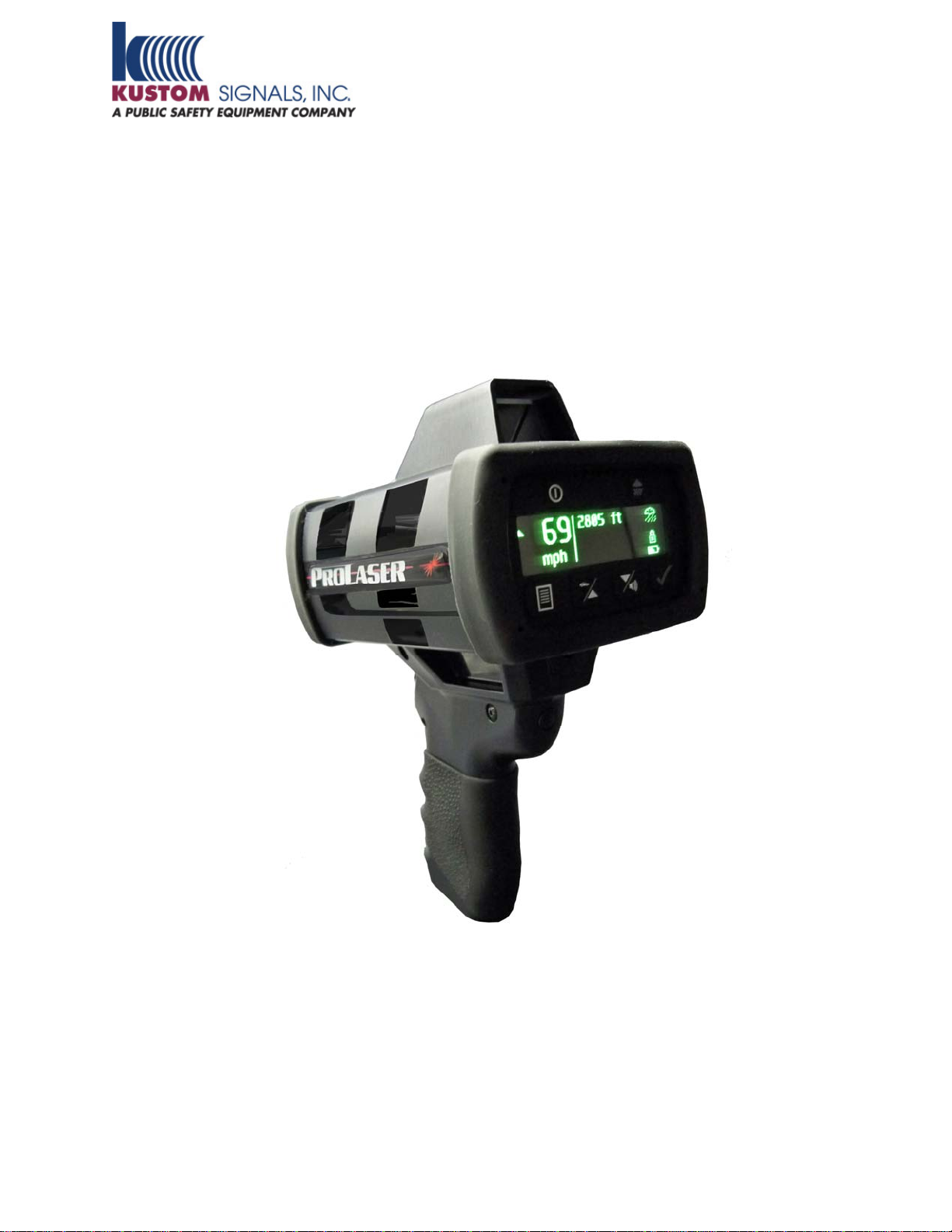
Product Description
Manual Part Number:
006-0966-00 Rev. 3 1-1 ProLaser 4
Chapter 1
Product Description
General Description
This chapter provides a high-level product description of the ProLaser 4 traffic safety lidar.
This product is the latest generation of ProLaser lidar, the most technologically advanced
instrument available for speed detection and enforcement. In a compact, handheld package,
the ProLaser 4 offers the versatility of direct range and speed measurement. The unit offers a
number of improved operating features and specifications which make it easier to use and
service and easier to train personnel in its use. These improvements include:
Improved range, accuracy and resolution
Reduced size and weight – Only 2.5 lbs (1.1 kg) with batteries
Waterproof to IP 67 and NEMA 6
Three (3) ways to power:
oSelf-contained, off-the-shelf, rechargeable NiMH or Alkaline AA batteries
o12 VDC car charger
oUSB from Mobile Data Computer (MDC)
Improved power management features with voltage level monitoring and “sleep” modes
to conserve battery power
Event recall with date and time stamp – capable of storing 1,000 records
Display lock
Tamper detection lockout
Simpler user interface with dual function controls
Graphical Head-up Display (HUD)
Selectable aiming reticles
Self-illuminating OLED (organic light emitting diode) rear display for high contrast
visibility day or night
Improved poor weat
th
he
er filter that improves performance in fog, rain, snow and dust
Rubber covers to protect the unit’s critical areas
Ergonomically designed pistol-style handle for reduced arm and wrist fatigue
Optimally designed center of gravity for well-balanced grip
Rugged pistol grip sleeve with finger grooves, replaceable
Both novice and experienced users will find the ProLaser 4 easy to operate, thanks to the use
of advanced technologies and superior target specific identification.

Product Description
ProLaser 4 1-2 Manual Part Number:
006-0966-00 Rev. 3
System Components
The ProLaser 4 lidar speed detection system consists of the following components:
ProLaser 4
ProLaser 4 to PC Cable (Commercial off-the-shelf (COTS) USB cable)
12VDC to 5VDC USB power adapter
Eight (8) off-the-shelf, rechargeable NiMH AA batteries and charger
Operator's Manual on CD
Quick Start Guide
Eye safety certification
Accuracy calibration certification
Optional Components
Shoulder stock
Hard carrying case
Tripod kit
Regional options and languages are available
Data management software
Control Locations
Operation of the ProLaser 4 primarily involves using the integrated rear display and the control
buttons that are located on the back panel of the unit, the Head-up Display (HUD) on top of the
unit and the trigger that is used to fire the unit. Additional control is provided using the USB
and power cable connectors. All control buttons on the rear of the ProLaser 4 are dual control
buttons, except for the Menu button. A brief description of the controls is provided below.
More detailed description will be provided in Chapter 2 System Operation.
A. Organic Light Emitting Diode (OLED): A display window that shows speed, range,
command menus and unit status in a text or two-dimensional icons to indicate modes of
operation, power levels, etc..
B. Power button: A dual-function button used to turn the unit On and Off and to control rear
display brightness.
C. Weather button: A dual-function button used to set the unit’s Poor Weather feature and
set HUD Brightness.
D. Menu button: Used to enter the Menu setup mode and configure the unit’s major
functions. In Menu mode, pressing the menu button exits the menu system and returns
the ProLaser 4 back to its most recent operating mode.
E. Speed/Up button: A multi-function button that toggles between Speed and Range mode
and Range mode. A press and hold of this button in Speed and Range mode will toggle
the operation between Both and Receding mode. This button is also used to navigate
between the Menu setup screens in Menu mode. This button is referred to as the up
button in Menu mode.
F. Down/Volume button: A multi-function button that sets the audio alert sound level in
Speed and Range mode and in Range mode. A press and hold of this button in Speed
and Range mode will toggle the operation between Both and Approaching mode. It is
also used to navigate between the Menu setup screens in Menu mode. This button is
referred to as the down button in Menu mode.

Product Description
Manual Part Number:
006-0966-00 Rev. 3 1-3 ProLaser 4
G. Check button: A multi-function button that runs the unit’s self test when pressed for
three (3) seconds in Speed and Range mode or Range mode. The check button is also
used to lock and release speed and range displays. On Menu setup screens, the check
button is used to select menu options, or act as an enter button.
H. Head-Up Display (HUD): displays the aiming reticle, speed and range of a target.
I. Type A – USB Host Port: this port is for future development and is not used at this time.
J. Type B – USB Device Port: provides a means to connect an external power source or
external computer.
K. Trigger: Activates the range/speed measurement function.
Item Description Item Description
A OLED display G Check button
B Power button H Head-Up Display (HUD)
C Weather button I Type A - USB port
D Menu button J Type B - USB port
E Speed/up button K Trigger
F Down/volume button
Figure 1-1. ProLaser 4 Features
Shown with USB cover
removed for clarity.

Product Description
ProLaser 4 1-4 Manual Part Number:
006-0966-00 Rev. 3
This Page Intentionally Left Blank

System Operation
Manual Part Number:
006-0966-00 Rev. 3 2-1 ProLaser 4
Chapter 2
System Operation
General Description
This chapter provides a detailed explanation of the operating characteristics of the ProLaser 4
speed detection system.
IMPORTANT The following guide to operating the ProLaser 4 lidar system is
not intended to be a training program. Before operating this unit
or any other speed measuring system, Kustom Signals, Inc.
urges all users to have training in radar and lidar speed
monitoring devices. Contact your District Manager or Kustom
Signals, Inc. at 1-800-4KUSTOM (1-800-458-7866) for further
details.
The ProLaser 4 is a versatile instrument that measures both the range and velocity of selected
targets. The advanced technology of the ProLaser 4 provides pinpoint aiming capability,
permitting the user to isolate a single vehicle out of a group.
Rather than using microwave transmission employed by traditional traffic radar systems, the
ProLaser 4 uses invisible light waves that are much higher in frequency. The beamwidth of the
ProLaser 4 is less than 3 feet (1 meter) wide at a target range of 1000 (305 meters) feet, which
provides the user with target specific identification.
The technology used by the ProLaser 4 to measure distances and speeds is referred to as
lidar, which stands for light detection and ranging. When the trigger is pulled, the ProLaser 4
sends out hundreds of invisible infrared laser light pulses per second. As each pulse is
transmitted, a timer is started, and when the energy of a laser pulse is reflected from a target
and received by the ProLaser 4, the timer is stopped. From the elapsed time taken for the
laser pulse to strike and return from the target, the distance to the object is calculated with the
known speed of light through the atmosphere. If the target is moving with respect to the
ProLaser 4, a sophisticated algorithm is used to derive the speed of the target from a
successive number of range calculations. This speed determination is then displayed to the
user.
Tips for Nighttime Operation
When operating the ProLaser 4 at night, the user may want to adjust the brightness of the rear
display and the HUD to compensate for the lower ambient light levels. Otherwise, the HUD
may be lost in the headlights of approaching vehicles, if using the single aiming reticle.

System Operation
ProLaser 4 2-2 Manual Part Number:
006-0966-00 Rev. 3
Control Descriptions
In Chapter 1 Product Description, the locations of the operating controls and displays were
introduced. This chapter will provide detailed descriptions of each control and display.
IMPORTANT Use of controls, adjustments or performance of procedures
other than those specified is not recommended. Adherence to
the instructions contained in this manual insures the device
works at peak performance.
Trigger
The trigger of the ProLaser 4 performs two (2) functions. When the trigger is pulled, it
activates the firing of laser pulses and the range and speed measurement functions of the
system. When the trigger is released, it causes the ProLaser 4 to lock the current measured
speed and/or range in the HUD and rear display, depending on the current operating mode of
the ProLaser 4.
Rear Display Control Buttons
Most of the control buttons that are located adjacent to the rear display provide dual and multi-
functionality based on whether the unit is in Speed and Range mode or in Range mode, or
within the Menu setup screens.
Power Button
The power button performs two (2) functions:
Power the ProLaser 4 On and Off
Adjust the brightness of the rear display
This button is used to turn the ProLaser 4 On and Off and is used to set the brightness of the
rear display. If the ProLaser 4 is off, a single press and release of the power button will turn
the ProLaser 4 On. Once it has powered on, press and hold the power button for three (3)
seconds to power the ProLaser 4 Off. (The ProLaser 4 will go into Sleep mode after two (2)
minutes of inactivity and will completely power down after 15 minutes of inactivity.)
When operating in Speed and Range mode, or in Range mode, a single press of the power
button will bring up the Rear Display Brightness Screen. Additional presses of the power
button will increase the rear display brightness by one level until the rear display is at
maximum brightness. An additional press will reset the brightness to the minimum brightness
setting. There are five (5) brightness settings ranging from minimum to maximum. Each
increment is indicated by three (3) vertical lines. In the following graphic, there are six (6)
lines, indicating that the current setting is two (2). Pressing the power button six (6) times
cycles through all the settings (1-2-3-4-5 and back to 1).
Figure 2-1. Rear Display Brightness Screen
System Operation
Manual Part Number:
006-0966-00 Rev. 3 2-3 ProLaser 4
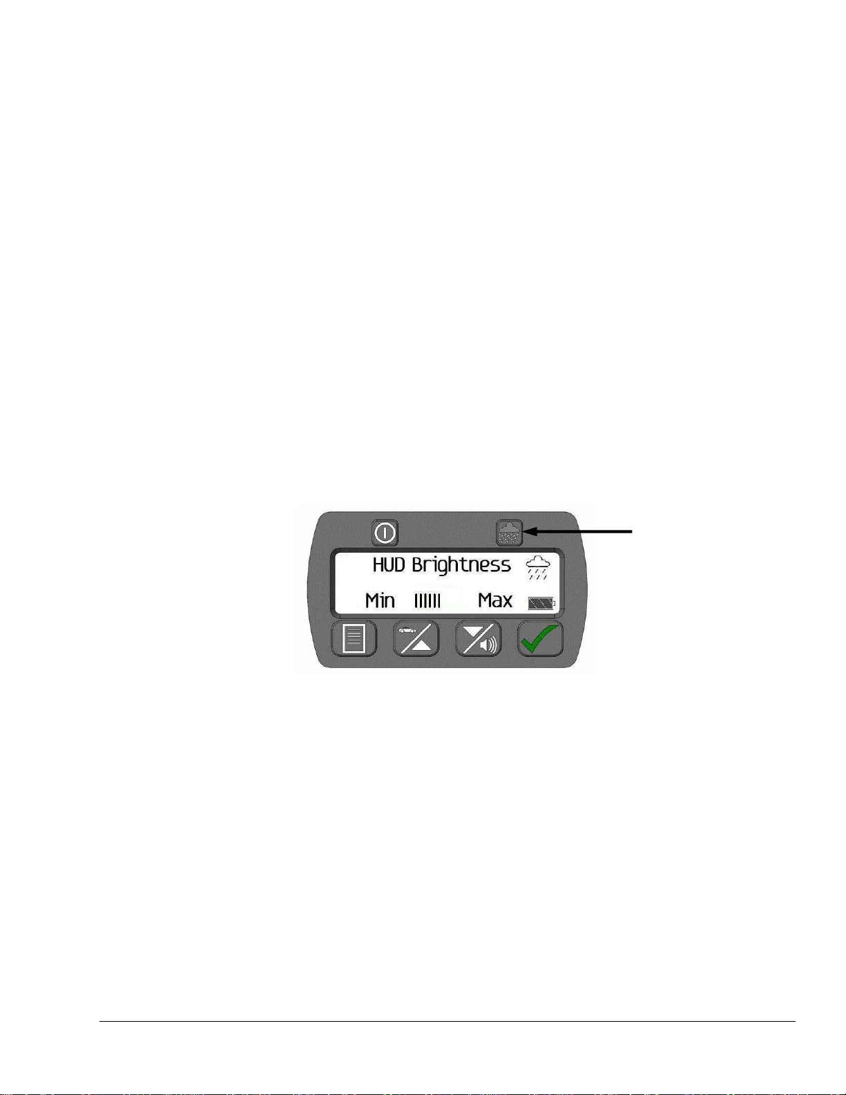
Weather Button
The weather button performs two (2) functions:
Turn the poor weather filter On and Off
Adjust the brightness of the Head-Up Display (HUD)
When operating in Speed and Range mode, or in Range mode, a press and hold of the
weather button activates poor weather mode. A subsequent press and hold will turn this
function off.
Also, when operating in Speed and Range mode, or in Range mode, the weather button is
used to set the brightness of the HUD. A single press of the weather button will bring up the
HUD Brightness screen. Additional presses of the weather button will increase the HUD
brightness by one level until the HUD is at maximum brightness. An additional press will reset
the brightness to the minimum brightness setting. There are five (5) brightness settings
ranging from minimum to maximum. Each increment is indicated by three (3) vertical lines. In
the following graphic, there are six (6) lines, indicating that the current setting is two (2).
Pressing the weather button six (6) times cycles through all the settings
(1-2-3-4-5 and back to 1).
Avoid using excessively bright settings for lower level ambient light conditions as this makes
target identification more difficult. Upon being powered up, the ProLaser 4 automatically
defaults to the brightness level set at the factory.
Figure 2-2. Weather Button Location
In Menu setup mode, press the weather button once on any of the Menu screens to set the
unit’s Poor Weather feature. The weather icon displays on the rear display as shown above
whenever the unit is set for poor weather. This feature enables the unit to work more
efficiently in adverse weather conditions for ranges greater than 200 feet (60 meters).
In Speed and Range mode, or Range mode, press and hold the weather button for three (3)
seconds to set Poor Weather mode.
Weather button
System Operation
ProLaser 4 2-4 Manual Part Number:
006-0966-00 Rev. 3
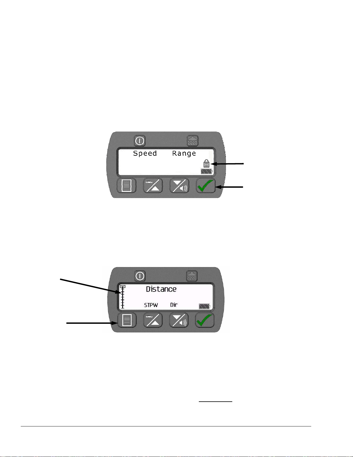
Check Button
The check button is located on the back panel. This button is used to initiate three (3)
functions.
In Speed and Range mode, or in Range mode, press and hold the check button for
three (3) seconds to initiate a self-test. Refer to Accuracy Tests in Chapter 4 Periodic
Maintenance for self-test message details.
The check button is also used to activate Display Lock after taking range or speed
readings. Press the check button once after releasing the trigger to lock the reading on
the display. The lock icon displays to indicate Display Lock. To clear the locked range
and speed displays in Lock mode, momentarily press and release the check button.
The check button is also used to select menu options. Press the button when a menu
or menu option is displayed to access the selected menu or select the displayed option.
Figure 2-3. Check Button Location
Menu Button
The Menu button is the only button on the back panel that is a single-function button. In Speed
and Range mode, or in Range mode, press the menu button to enter the ProLaser 4 Menu
system. A menu tree icon on the left side of the rear display indicates where the user is within
the menu system. Text above the up and down buttons identifies the previous and next menu
function. Due to regional regulations, not all menus are available in all areas.
Figure 2-4. Menu Mode – Displaying the Distance Menu Selection
The configurable menu functions are:
Distance Continuous/Single
Events
Set Direction mph-km/h
Set Time/Date
DIF-TEST HUD options
Stopwatch
Note: Not all menus are available on all units, due to regional requirements. For
example, on units sold in Canada, the units WILL NOT have the mph-km/h
menu selection. The unit will operate in metric mode only.
ProLaser 4 menu operation is covered in Chapter 3, Using the ProLaser 4 Menu System.
Menu tree
Menu button
Check button
Lock icon
System Operation
Manual Part Number:
006-0966-00 Rev. 3 2-5 ProLaser 4
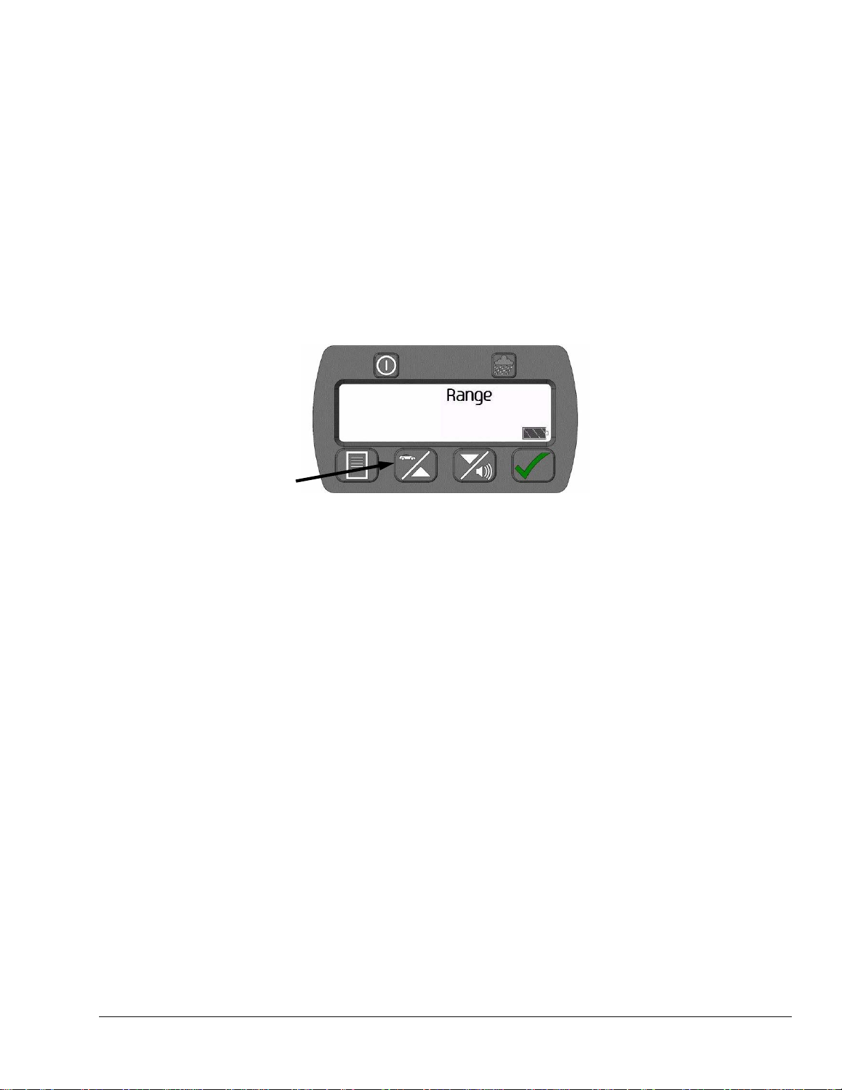
Speed/Up Button
The speed/up button performs several different functions:
To set the unit to either Speed and Range mode, or to Range mode
To toggle between Receding only and Both mode
To navigate between screens and options in the Menu mode
When operating in Speed and Range mode, or Range mode, press and release of the
speed/up button to toggle between the two (2) modes.
Also while operating in Speed and Range mode, or Range mode, the user may press and hold
the speed/up button to toggle selection between both and receding only targets.
If the user has entered the menu system, each press of the speed/up button will scroll up one
level in the menu system.
Figure 2-5. Speed/Up Button – Range Mode Display
Down/Volume Button
The down/volume button is used to perform the following functions:
To set the volume level of the audio alerts when the unit is in either Speed and Range
mode or Range mode
To toggle between Approaching only and Both mode
To navigate between options when in Menu mode
When operating in Speed and Range mode, or Range mode, the user can press and release
the down/volume button to increase the audio alert volume one (1) increment. There are five
(5) sound levels, from minimum to maximum, plus one (1) setting with no sound (Min-2-3-4-
Max and Off). Once the volume has reached level 5, the next press of the volume button will
turn the volume completely Off. Another press of the volume button will advance to volume
Min. setting. Each increment is indicated by three (3) lines on the display. Zero (0) lines
indicate off, three lines indicates Min. In the following figure, the six (6) lines on the display
indicate that the volume is currently set to setting two (2).
Speed/up button

System Operation
ProLaser 4 2-6 Manual Part Number:
006-0966-00 Rev. 3
Figure 2-6. Volume Menu (Setting 2 Shown)
Note: On units sold in Canada, the units will still make some audible noise when the
volume is turned Off.
Also while operating in Speed and Range mode, or Range mode, the user may press and hold
the down/volume button to toggle between Both and Approaching only mode.
If the user has entered the menu system, each press of the down/volume button will scroll
down one level in the menu system.
Down/volume button
Lines indicate setting
(three (3) lines per
increment)
Table of contents


