Shimpo DT-5TG User manual

Aros
COOOGOOOorStG
0.0
:
http://www
1718veb.
net
FEATURES:
©
Multiple
purpose
digital
tachometer
measures
rotational,
linear,
and
flow
rate
speeds.
If
desired,
this
unit
can
also
function
as
an
elapse
time
counter
or
ratiometer.
New
Digital
Tachometer
@An
insertion
of
new
cassette
type
adapter
increases
functions.
(CASSETTE
TYPE
OPTIONAL
UNIT)
(including
DC
POWER
MODEL)
Instruction
Manual
@
All
functions
are
easily
set
via
front
panel
keys.
@Easy
mounting,
no
brackets
or
screws
are
required.
e
Any
AC
voltage
between
85
and
264V
will
power
to
DT-5TG.
{DC
powered
DT-5TG-DC:DC9
~35
V)
*
Thank
you
for
your
purchase
of
SHIMPO
new
Digital
Tachometer/
Speedometer
DT-5TG.
IMPORTANT:Read
rule
for
safe
installation,
operation
and
instruction
manual
carefully
and
SAVE
THIS
INSTRUCTION
MANUAL.
(POWER)
Make
sure
AC
voltage
is
between
85
and
264V.
(DC
powered
DT-5TG-DC:DC9
~35
V)
When
installing
unit,
keep
power
and
sensor
wires
separate.
(INPUT
SIGNAL
WIRE)
Connection
wiring
from
sensors
shall
not
be
kept
in
the
same
or
parallel
conduit
or
cable
as
the
power
source,
power
or
high
voltage
cables
to
avoid
noise
which
may
cause
mulfunction.
Use
shielded
wire
for
input
power
connections
in
the
shortest
possible
metal
conduit.
(TERMINAL)
After
inserting
wires
tighten
terminals
securely.
(ENVIRONMENT)
Protect
instrument
from
water,
oil
and
corrosive
materials.
Do
not
use
it
in
the
place
of
vibration
or
shock.
Use
it
in
the
place
of
normal
temperature
and
no
dew.
In
case
of
using
the
instrument
near
motor
including
servo
motor,
inverter,
solenoid
contact
switches,
avoid
noise
by
static
electricity,
etc.
Do
not
use
it
in
the
hazardous
area.
HOUUUUUUUUUUY
0 O
:
010-
51662244
Arete
00000000
D-5
O
:
http:
//
ww
1718veb.
net
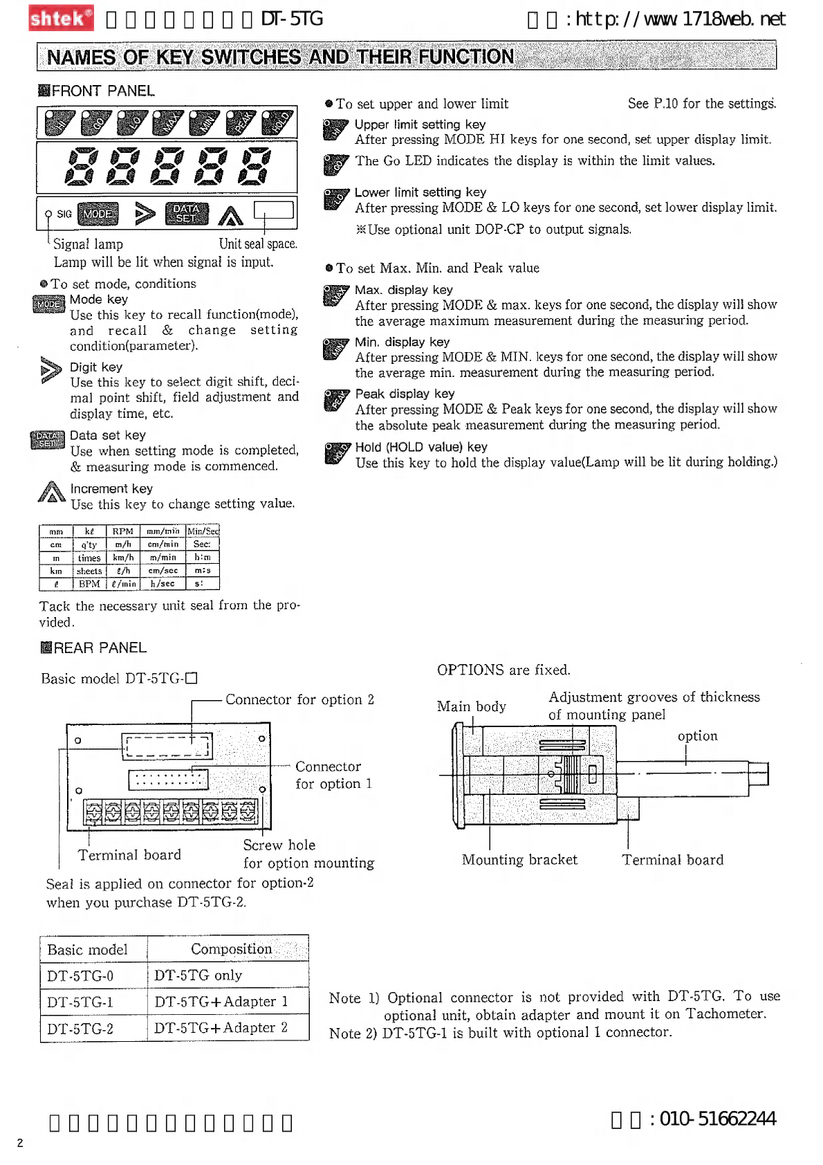
‘Signal
lamp
Unit
seal
space.
Lamp
will
be
lit
when
signal
is
input.
®
To
set
mode,
conditions
Mode
key
Use
this
key
to
recall
function{mode),
and
recall
&
change
setting
condition{parametetr).
»
Digit
key
Use
this
key
to
select
digit
shift,
dect-
mal
point
shift,
field
adjustment
and
display
time,
etc.
Data
set
key
Use
when
setting
mode
is
completed,
&
measuring
mode
is
commenced.
.
Increment
key
Use
this
key
to
change
setting
value.
[Can
[Ee
RP
[mr
le
qty
|
m/h
|
em/min
times
|
km/h
m/min
him
sheets}
g/h
em/sec
s
Tack
the
necessary
unit
seal
from
the
pro-
vided.
HREAR
PANEL
Basic
model
DT-5TG-0
‘
Pad
peed
Dead
Ged
peel
ee
=
=
j
Terminal
board
Seal
is
applied
on
connector
for
option-2
when
you
purchase
DT-5TG-2.
Connector
for
option
2
Connector
for
option
1
Screw
hole
for
option
mounting
HOUUUUUUUUUUY
Basic
model
Composition
ee
Ee
DT-5TG
only
DT-5TG-1
DT-5TG+
Adapter
1
—
DT-5TG-2
DT-5TG+
Adapter
2
See
P.10
for
the
settings.
Upper
limit
setting
key
After
pressing
MODE
HI
keys
for
one
second,
set
upper
display
limit.
The
Go
LED
indicates
the
display
is
within
the
limit
values.
t
Lower
limit
setting
key
After
pressing
MODE
&
LO
keys
for
one
second,
set
lower
display
limit.
Use
optional
unit
DOP-CP
to
output
signals.
®To
set
Max.
Min.
and
Peak
value
F
Max.
display
key
After
pressing
MODE
&
max.
keys
for
one
second,
the
display
wili
show
the
average
maximum
measurement
during
the
measuring
period.
Min.
display
key
After
pressing
MODE
&
MIN.
keys
for
one
second,
the
display
will
show
the
average
min.
measurement
during
the
measuring
period.
?
Peak
display
key
After
pressing
MODE
&
Peak
keys
for
one
second,
the
display
will
show
the
absolute
peak
measurement
during
the
measuring
period.
7
Hold
(HOLD
value)
key
Use
this
key
to
hold
the
display
value(Lamp
will
be
lit
during
holding.)
OPTIONS
are
fixed.
Adjustment
grooves
of
thickness
pal
ROSY
of
mounting
panel
option
Sila]
aM
Mounting
bracket
Terminal
board
Note
1)
Optional
connector
is
not
provided
with
DT-5TG.
To
use
optional
unit,
obtain
adapter
and
mount
it
on
Tachometer.
Note
2)
DT-5TG-1
is
built
with
optional
1
connector.
O O
:
010-
51662244

ATEI
OOOOOOOO
-5T
MOUNTING
O O
:http://ww
1718veb.
net
DIMENSIONS
a
soma
ea
This
instrument
features
easy
“Touch-in-
mount
method”.
Adjust
mounting
bracket
to
meet
with
the
thickness
of
mounting
panel.
1l.
Insert
the
provided
adjusting
tool
into
position
adjusting
hole.
(See
fig.)
2.
Lift
adjusting
tool
slightly
and
move
mounting
bracket
left
and
right.
3.
Set
the
hook
of
the
mounting
bracket
into
groove
of
panel
thickness
adjustment.
X
Please
be
careful
not
to
warp
the
instrument
body
by
mounting
too
strongly.
Mounting
Bracket
Adjustment
groove
The
instrument
is
set
to
5th
groove
at
factory.
#1f
the
mounting
is
too
loose,
proceed
to
the
next
groove
to
tighten
the
mounting.
CONNECTIONS
-
x
Connect
power
with
sensor
on
the
terminals
located
in
the
rear
of
tachometer.
X
Signai
wire
from
sensor
shail
be
shielded
separately
from
power
line.
#
Connecting
wires
from
sensor
shal!
not
be
in
the
same
meta!
conduit
of
high
power
line
such
as
electric
source,
power
high
pressure
line
to
immune
©
noise
and
to
avoid
mulfunction.
How
to
insert
wires
to
terminals.
(For
safety,
turn
power
OFF
for
sure.)
SSEERISIZe
Loosen
screws
with
screwdriver.
Fasten
solderless
terminals
onto
wires
and
insert
them
into
the
loosened
screws
as
shown
in
fig.
on
left.
X
Tighten
the
screws
with
the
screwdriver.
HOUUUUUUUUUUU
Thickness
of
panel
(1.2-~5mm)
BE
Thickness
of
panel
|
Panel
thickness
adjusting
groove
Mounting
1.2~
1.6%
bracket
OPTIONAL
UNIT
“Option
1
(EXAMPLE:
DOP-BC,
SD,
PO)
14g
E
a0.
|
5
I
E
H
mpieg
*Option
2
(EXAMPLE:
DOP-FV,
VF)
To
mount/remove
into/from
panel
1.
Insert
DT-5TG
into
panel
cutaway
as
the
mounting
bracket
in
level
position.
PULL
DT-5TG
straight
out
to
remove.
(it
DT-5TG
is
loose
i
in
the
panel
Cutaway,
t
reset
2.
From
the
rear,
alternately
push
unit
to
left
and
right.
This
will
free
unit
from
bracket
for
easy
removal.
See
instruction
manual
for
the
optional
unit
mount-
ing.
5th
groove
lst
groove
B
Panel
thickness
adjusting
groove
Adjusting
tool
Use
the
following
shield
wires
Shield
wire
Sensors
Rotary
pulse
generator
RE1-O1C
SE-P12
SE-R
SE-G
Proximity
switch
Retro-reflective
sensor 3
wires
0.3sq.
=
sensor
2
wires
Magnetic
pick
up
sensor
SE-M
When
output
voltage
10Hz.,
0.3Vp-p
or
more
is
required.
When
output
voltagel00Hz.,
0.3Vp-p
or
more
is
required.
When
output
voltage
1000Hz.,
15Vp-p
or
more
is
required.
When
output
voltage
10000Hz.,
6.0Vp-p
or
more
is
required.
O O
:
010-
51662244
Output
votiage
of
magnetic
pick
up
sensor
3

4
Arte
00000000
D-5
O
O
:
http://www
1718veb.
net
|
CONNECTIONS
-
EICONNECTION
DIAGRAM
a
t
Signal
Type
of
input
According
to
sensors,
connections
are
different
as
follows;
Model
(Shimpo)
Sensor
Input
,
Connection
Power
Sensors
Terminals
Earth
i
7
N
1513
|
5]
5
Blo
|
Contact
signals|
Relay
switch
5~9
oe
i
-
tput
from
SHIMPO
Open
Reatro-reflective
:
es
e
puse
ma
J
sj
è|
2/88]
z
collector
sensor
SE-R2
|
4~6~8
ee
ll
gst
eae
ae
be
s|
$|
#82
wi
erminals.
a
z|
2
A
Se
Rectangular
miy
pulse
generator
aaa
2\Sensors
shail
be
connected
with
ACBS~264V
zy
elegis
wave
gar
sensor
2
4-79
specified
terminals
and
other
For
DT-STG-0G
D09~38¥
g
&@a
t
Proximity
switch
terminals
shall
be
blank.
Multple
Connect
to
10n
plus
a
Sine
wave
Magnetic
sensors
can
not
be
connecied
&
Zon
minus
Sensor
connections
pick-up
sensor
simultaneously,
|
MODE
AND
PARAMETER
—
This
instrument
can
be
used
as
1.
Speedometer
and
2.
Elapse
time
counter.
Before
shipment,
this
instrument
has
been
adjusted
as
rotational
tachometer
which
has
the
PERIODIC
MULTIPLICATION
function
(Mode
1)
of
the
condi-
tions
in
the
chart
below.
You
may
use
this
instrument
without
any
resetting
if
your
requirement
is
within
the
preset
condition.
Setting
items
Mode
No.
Setting
Mode
Parameter
1
Nos.
of
input
pulse
Parameter
2
Preset
rpm{Sensor)
50000
rpm
Primary
setting
value
Mode
1
Periodic
multiplication
Display
value
when
reaches
|
50000
rpm
the
preset
value.
Parameter
3
Parameter
4
Decimal
point
20
rpm
Min.
rpm(Sensor)}
Parameter
5
l
second
Display
cycle
Parameter
6
O(No
function)
Pre-multiplication
function
|
Parameter
7
BEFORE
OPERATION
SET
AS
FOLLOWS.
1.
Mode
selection
1.
To
confirm
actual
rotational
speed
es
Mode
1:
Periodic
multiplication
2.
To
set
various
display
conditions
3.
To
set
various
display
conditions
Mode
2:
Elapse
time
counter
Self
circuit
test
Mode
5:
Test
mode
|
FUNCTION
(Mode)
selection
Select
mode
according
to
the
requirement.
multiplied
and
displayed.
Mode
No.
|
Mode
name
Applications
Main
purpose
Mode
1
|
Periodic
Nos.
of
pulse
and
pulse
|
Rotational
speed
flow
rate,
Multiplication
period
can
be
measured
and
|
and
peripheral
speed
Mode
2
|
Elapse
Process
time
will
be
dis-
time
played
from
process
length
counter
and
process
speed.
|
Mode
5
|
Test
mode
To
self-check
the
circuit
[FIELD
ADJUSTMENT
FUNCTION
To
measure
actual
rotational
speeds,
the
following
Field
adjustment
function
may
be
set.
Complicated
calculation
is
not
necessary
to
set
the
measuring
value.
If
DT-5TG
shows
900
rpm,
but
nos.
of
pulses
of
sensor
and
speed
reduction
ratio
is
not
known,
you
can
simply
input
the
actual
rpm
measured
with
handheld
digital
tachometer
as
the
set
rotational
speed
without
setting
parameter.
HOUUUUUUUUUUY
Elapse
time
Troubleshooting
Mode
3:Voltage
input
tachometer
Mode
4:To
use
ratiometer,
couple
optional
unit
DOP-RM
with
main
body.
HOW
TO
SET
2.
Adjust
Digit
&
Inc.
to
set
values.
E>
A
gi
a
To
shift
digit,
use
this
key
switch.
A
eee
To
increase/decrease
fig.,
use
this
key.
*
Every
time
press
this
key,
the
fig
shifts
0>
1>
2
s
reune
8
—
9-
periodically.
DATAN
r
rm
a
x
F
Uf
fs
Aa
~
Start
measuring
—
O O
:
010-
51662244
PETENTE
S
SEYE
ERE
AS
ARTO
3.
Press
Date
set
key.
RETANA
RARE

EES
00000000
-5TG
0
‘SETTING
MODE
——
[O
:
http://www
1718veb.
net
Operation
L
Display
Remarks
1.
Input
power
i
ER
voltage
power
is
input,
00000
will
be
dis-
(AC85-264V)
played
and
change
to
0.
|2
Press
MODE
and
T
Set
mode
will
be
displayed.
DATA
SET
key
at
#éWhen
purchased,
periodic
multiplication
mode
ime
for
5
sec.
CE]
Mode
primarily
set
will
be
displayed.
Measuring
mode
will
be
changed
to
setting
|
mode.
3,
Press
inc.
key
and
select
|
Mode
3
&
4
will
be
displayed
at
the
time
optional
:
the
required
mode.
Mode
1
|
nit
will
be
coupled.
Mode
1:
To
measure
Rotational,
A
TE]
mode
2
|
At
each
touch
of
inc.
key,
ohh}
Peripheral,
&
Flow
rate,
select
A
-$r
Mode
5
will
be
periodically
changed.)
periodic
multiplication
mode,
MODE.{
:.To
measure
rotational
speed,
peripheral
speed,
flow
rate,
select
PERIODIC
MULTIPLICATION
FUNCTION.
|
Set
Parameter
in
the
following
procedures
to
set
various
display
conditions.
SET
ITEM
RIEXAMPLE
OF
SETTING
—
Peripheral
speed
—
Setting
item
Primary
set
value
=i
CONDITION
Mode
No.
Mode
1:
Periodic
multiplication
RPM
of
variator:
1000rpm
***Parameter
2
|
method
i
:
(MGS
is
built
in
60P/r)
-*+*Parameter
1
Parameter
1
~[
Nos.
of
input
pulses
|i
p/r
With
Reduction
gear
1/10
Parameter
2
Set
rpm
(sensor)
50000
rom
i
Pulley
ratio
1/2
|
Parameter
3
E
value
50000
rpm
Rol!
dia.
1.0m
a
4
Decimal
point
None
~]
ETIN
:
:
—4
-
When
variator
runs
at
1000rpm,
and
the
peripheral
speed
Parameter
5
eo
seieor
10
rpm
|
per
m/min.
is
requested,
Parameter
6
__|
Periodic
display
1
sec.
the
peripheral
speed
of
roll
dia.
1.0m
is
obtained
from
the
Parameter
7
Pre-multiplication
formula;
|
function
0
{
no
function)
_}
1000rpm
x
1/30
X
1/2
(1%
3.14)=157m/min.
“Parameter
3
SETTING
MODE
Remarks
When
voltage
power
is
input,
00000
will
be
displayed
and
change
to
0.
Operation
Display
1
Input
power
:
(AC85-264V)
lZ
Press
MODE
and
DATA
SET
key
r
[pE]
at
same
time
for
5
sec.
zia]
Mode
1
Set
mode
will
be
displayed.
#
When
purchased,
periodic
multiplication
mode
primarily
set
will
be
displayed.
3
Measuring
model
will
be
changed
to
setting
mode.
SETTING
PARAMETER
a
(1
To
set
Parameter
i
(Nos.
of
Input
pulses)
Example:
In
case
60
p/r
l.
Set
mode
1
Parameter
No.
9.
Press
mode
key.
Alternatively
flashing
Gee
digit
key
and
increment
key)
at
the
same
time
and
set
60.
Primary
set
at
1
p/r.
3,
Press
digit
key
and
the
top
fig.
flashing.
4.
Press
digit
key
to
flash
2nd
digit.
5.
Press
inc.
key
to
shift
2nd
digit
to
6.
6.
Press
digit
key
to
flash
Ist
digit.
mao
Pt
atone
fe
it
7.
Press
inc.
key
to
shift
1st
digit
to
0.
Even
after
setting
is
completed,
figures
flash.
To
shift
digit,
press
this
digit
key.
Everytime
pressing
To
inrease/decrease
figures,
press
this
key.
this
key,
the
flashing
digit
will
shift
toward
right.
The
Everytime
pressing
this
key
G-1-
2-308
-9
value
flashing
means
“Shifting”.
the
flashing
digit
will
shift
toward
right
and
back
to
|
the
beginning
figure.
HOUUUUUUUUOU.
0
O
:
010-51662244
`
EPET
ERARE

Arete
00000000
D-5
MODE:
{To
measure:
rotational
;
Speed,
peripheral
speed,
flow
2
Parameter
2
(Preset
rom)
setting
1.
Press
mode
key.
Press
digit
key
and
inc.
key
simultaneously
and
set
1000.
2.
Flash
top
digit.
3.
Change
top
digit
zero.
4.
Flash
4th
digit.
5.
Change
4th
digit
to
1.
3
Parameter
3
(The
display
value
at
the
set
rpm}
setting
1.
Press
mode
key.
2.
Press
digit
key
and
Inc.
key
to
set
157.
(See
Parameter
1
operation.)
OO
:
http:
//
ww
1718veb.
net
>
A
>
A
Example:
To
set
1000
rpm.
Eo
a
e
No,
Alternatively
flashing
Primary
setting
50000.
CERE
m
on
or
at
at
as
m
Fi
a)
ore
re
ort
Fa
ores
ka
at
ad
aor
rtm
Pt
wW
tA
Setting
is
completed.
Example:
To
set
157
Farameter
No.
L
Alternatively
flashing
a
es
BE
y
B
y
3
eras
ot
af
Primary
setting
50000.
Setting
is
completed.
4.
Parameter
4
(Decimal
point)
setting
1.
Press
mode
key.
2.
Press
mode
key
again
to
get
back
to
parameter
9.
For
example:
To
display
157.0-
set
as
1.
When
decimal
point
display
is
required
in
parameter,
set
the
figure
in
parameter
3
as
to
add
0
after
the
decimal
point.
01570
2.
After
pressing
mode
key,
set
Parameter
4.
3.
Press
digit
key
and
shift
decimal
point
to
the
desired
position.
Decimal
point
shift
everytime
pressing
digit
key.
5
Parameter
5
(Min.
rpm
of
sensing
gear)
setting
1.
Press
mode
key.
and
set
15.
(See
Parameter
1
operation.)
For
example:
When
not
to
set
decimal
point.
>
2.
Press
digit
ke
d
Inc.
|}
and
Inc.
key
simultaneousl
ress
digi
yan
c.
key
key
y
>
A
Parameter
No.
Alternatively
flashing
No
decimal
point
in
primary
setting.
Setting
is
completed.
Example:
To
set
15
rpm.
Parameter
No.
Alternatively
flashing
Primary
setting
10
rpm
Setting
is
completed.
6
Parameter
6
(Setting
display
cycle)
1.
Press
mode
key.
2.
Press
digit
key
once,
then
the
primary
setting
of
one
sec.
will
flash.
3.
Select
0.50
sec.
Select
the
best
display
cycle
from
0.25,
0.50,
1,
2,
4,
8,
16sec.
>
>
For
example:
To
set
0.5
sec.
Parameter
No.
i
Altenatively
flashing
L——
Primary
setting
is
1
sec.
ares
va
ri
h
wy
t
Display
cycle
will
be
shifted.
Setting
is
completed.
pin
24-8
16
0.25
0.505
L
*
HOUUWUUUUUUUUY

U
O
:
http:
//
ww
1718veb.
net
select
PERIODIC
MULTIPLICATION
FUNCTION.
shtek’
o
o
00000
DO
O-sIG
‘rotational
speed,
peripheral
‘speed,
flow
ra
7
Parameter
7
(Pre-multiplication)
setting
For
example:
For
the
time
of
no
function.
go
Parameter
No.
Toe
u m
t
Alternatively
Primary
setting
is
#
Note:
See
below
for
the
details
of
pre-multiplication
function.
1.
Press
mode
key.
>
LE
0
Zero
will
display.
2.
lf
the
digit
key
is
processed,
primary
setting
is 0.
Everytime
pressing
0:
Shows
no
function.
digit
key,
the
number
1:
Pre-multiplication
at
stopping.
pe
0-
1-24
2:
Pre-multiplication
at
speed
reducing.
will
shift.
Q
Setting
is
completed.
Measurement
will
be
started.
or
measurement
will
be
displayed.
1.
Press
data
det
key.
X
Setting
mode
will
be
shifted
to
measuring
mode
and
the
measurement
will
be
started.
Xu ri
Setting
values
will
be
stored
at
even
when
the
eleçtirc
power
is
off
by
accident.
Set
parameter
may
be
recommended
to
be
written
on
the
name
seal
in
the
parameter
note
for
convenience.
Set
mode
and
parameter
will
automatically
be
locked
for
no
man
to
change
the
set
data.
To
change
setting
and
release
lock,
press
mode
and
data
set
keys
at
the
same
time
for
over
5
sec.
Mode
nos.
set
initially
will
be
displayed
and
resetting
can
be
ready.
[To
use
pre-arithmetic
function
Pre-arithmetic
function
When
the
speed
of
the
rotatings
increase
or
decrease
rapidly,
the
conventional
speedometer
may
not
follow
the
display,
of
which
value
remains
at
the
time
of
the
machine
stop.
DT-5TG
will
pre-multiply
the
speed
and
absorb
the
delay
in
the
display.
1.
Pre-arithmetic
at
stopping
After
rapid
stopping,
as
the
input
pulses
disappear
(in
case
of
input
pulses
disappear
within
0.25sec.),
the
display
will
show
0
quickly
because
of
pre-
arithmatic
function.
Press
digit
key
to
select
1.
1)
Pre-arithmetic
function
will
be
available
at
speed
of
7rpm
or
faster
(at
60p/r).
Example:
To
set
the
2nd
value
from
the
decimal
point.
1.
Change
Parameter
2,5
2902
tol
28
608
|
2.
Do
not
change
Parameter
3
(Leave
it
as
it
is.)
3.
Change
Parameter4,
52292.
toj
$a
ouuu
2.
Pre-arithmetic
at
reducing
sneed.
After
reducing
speed,
as
the
input
pulses
disappear
(in
case
of
input
pulses
disappear
within
0.25sec},
the
display
will
show
nearly
by
0
reverse-iunction
of
pre-arithmatic.
Puy
Press
digit
key
to
select
2.
2}
Pre-arithmatic
will
be
stopped
at
the
pulse
input
and
cycle
arithmatic
will
be
started.
‘OVERFLOW
DISPLAY
=
If
the
display
pass
over
the|
$9
42%
|Gncluding
decimal
point),
the
display
will
be
as
O0
O
:
010-51662244
7

Aros
COOOGOOO
SIG
OO
:http://
ww
1718veb.
net
[MODE
2;
TO
MEASURE
ELAPSE
TIME.
—
oe
Mode
2:
Elapse
time
counter
Note:
DT-5TG
may
not
be
used
as
elapse
time
counter
This
mode
allows
the
operator
to
correctly
time
a
if
the
optional
unit
DOP-FV
or
DOP-VF
is
attached.
certain
process.
ET
ITEM
BExample
of
Elapse
timer
=
S
"
x
Setting
|
Setting
item
|
Primary
set
value
*
Calculate
elapse
time
(Setting
example]
Parameter
1
|
Nos.
of
input
pulses
|
1
p/r
100m
DT-5TG
|
Parameter
2
Se
rpm(sensor)
|
200
rpm
Parameter
3
|
Change
over
in
the
|
Hour
and
min.,
only.
I
r
|
Varlable
speed
drive|
unit
of
hour,
min.
ee
i
Speed
reduce
~
L
|
(Reduction
ratio
1/50)
(iddrpm)
Parameter
4
|
Display
value
at
|02=00
Magnetic
pick
up
sensor
60
pulses
o
preset
speed.
|
Calculation
time
7
Parameter
Jev
Magnetic
pick-up
sensor
60
pulses/r
Parameter
5
|
Display
cycle
_|
1
sec.
_.
Parameter
2
deepsea
enn
nee
sh
eneteeenen
meer
ne
racane
cab
Enareg
nae
100
rpm
*
The
DT-5TG
is
set
to
the
abvoe
values
primarily
before
Linear
speed
=
PSD
of
rollerX
rpm
=0.1
3.14
x
100
*
1/50=0.628m/min.
shipment
from
SHIMPO
Elapse
time
=
Length
of
process
=
100
=
159,2min.
Linear
speed
0,628
Parameter
3
Seeererererrererrrra
a
Parameter
qovvuséeuvunvtn
2
hrs
39
min,
SETTING
MODE
Į
Operation
L
Display
Remarks
li.
Input
power
(AC85-264V)
When
voltage
power
is
input,
00000
will
be
displayed
and
change
to
0.
2,
Press
MODE
and
DATA
SET
|
|
Set
mode
will
be
displayed.
|
key
at
same
time
for
5
sec.
[ee
al
Mode
1
When
purchased,
periodic
multiplication
mode
primarily
set
Š
will
be
displayed.
x
Measuring
model
will
be
changed
to
setting
mode,
%
Press
inc.
key
and
select
the
Mode
3
&
4
will
be
displayed
at
the
time
optional
unit
will
be
required
mode.
coupled.
A
-P
-
Mode
2
|
At
each
touch
of
inc.
key,
pEi
-Esh
A
4
_|
will
be
periodically
changed.
1
Parameter
1
(Nos.
of
input
pulses)
setting
Example:
To
set
60
p/
p]
-
rt
-
1.
Set
mode
2
£
p
Parameter
No.
2.
Press
mode
key
ae
(Press
digit
key
and
inc.
Key
and
set
60.)
Saree
Alternatively
flashing
Ad
ceo
ao
Primary
set
is
1
p/r.
3.
Top
figure
flashes
>
gags
4.
The
2nd
digit
flashes.
>>
Gag!
i
T
a
iai
r
|
5.
The
2nd
digit
becomes
6.
A
moe
6.
The
Ist
digit
flashes.
>
eee
ens
——
7.
The
7th
digit
become
zero.
A
gga
8
The
set
data
flashes
even
after
completion
of
setting.
>
eurei
is
to
shift
the
digit.
A
puaa
is
to
be
used
to
increase/decrease
the figures.
Everytime
pressing
this
key,
the
digit
shifts
Everytime
pressing
this
key
01-238
toward
right
and
flashing
indicates
the
chang-
~—-9,
the
figure
changes.
ing
position.
|
2
Parameter
2
(Set
speed
rpm)
setting
Example:
To
set
100
rpm
Parameter
No.
1.
Press
mode
key.
eS
sa
ii
Alternatively
flashing
EERE:
-__
Primary
setting
is
200.
9.
The
top
figure
flashes.
>
gapt
3.
The
3rd
digit
flashes.
>
woe
oo
(4
Change
3rd
digit
to
1.
A
oe
raga
Setting
is
completed.
E
s0000000000000
OO
:
010-
51662244

shtek“
COOOOGOOOor5StG
MODE
2:
TO
MEASURE
ELAPSE
TIME
O O
:
http:
//
ww
1718veb.
net
E
co
4
Parameter
3
(Hr.
Min.
&
Sec.
unit)
setting
i.
Press
mode
key.
2.
Select
hour,
minute
unit.
Everytime
pressing
digit
key,
The
figure
will
be
changed
as
follows.
l-
mort
mo
ou
Note
1-Per
second
unit/For
example
99-
25
shows
99.
25
seconds
J.
Press
mode
key.
2.
Press
digit
key
to
flash
top
fig.
3.
Press
digit
key
and
inc.
key
to
set
0239.
(See
parameter
1
&
2
for
right
operation)
Note
1)
Concerning
limit
over
for
hour,
min.,
sec.,
unit.
display
range
for
hours,
mir,
sec.
is
99
=-
59,
For
example
in
case
02
=-69
is
set,
the
two
digits
show
Eferror)
when
pressing
mode
and
data
set
keys.
|
p
3
4
Parameter
4
(Display
value
at
preset
rotation/calculation
time)
setting
=>
AA
Setting
is
completed.
Example:
To
set
Hr.
Min.
setting
p
Parameter
No.
em
[z-s]
H
Alternatively
flashing
Hour
&
Min.
are
initiaily
setting.
Setting
is
completed.
Note
2--Per
hour
&
minute
unit,
min.
&
sec.
unit/For
example,
05
2.15
shows
5
hours
and
15
seconds.
xample:
To
set
2
hours
39seconds
sc
Parameter
No.
Sp
Primary
setting
is
02
1.00
Alternatively
flashing
To
remedy:
Press
digit
key
and
display
E
digit
and
reset
O~5
fig.
by
inc.
key.
5
Parameter
5
(Display
cycle)
setting
l].
Press
mode
key.
X
Select
the
best
display
cycle;
0.25,
0.50,
1, 2,
4,
8
or
16
sec.
2,
Press
digit
key
and
select
1
sec.
Everytime
pressing
display
cycle
key,
display
cycle
changes
from
p?1727
4
8-"
16
0.25-7
0.505
repeatedly-
Example:
To
set
1
sec.
Parameter
No.
fe
oe
al
a
Alternatively
flashing
i
Primary
setting
is
1
sec.
5>
o
Setting
is
completed.
6
Setting
is
over
and
start
measuring.
1.
Press
data
set
key.
Mode
will
be
changed
from
setting
mode
to
measuring
mode.
or
display
measuring
value.
x
When
power
is
off,
the
value
set
before
the
power
off
will
be
stored
in
memory.
lt
is
appropriate
to
make
notes
on
parameter
seal,
located
on
top
of
the
DT-5TG.
The
preset
mode,
parameter
set
are
locked
automati-
cally
for
protecting
from
mishandlings.
To
unlock
and
change
the
settings,
press
mode
key
and
data
set
key
simultaneously
for
over
5
seconds.
The
mode
nos.
set
initially
will
be
displayed.
Resetting
can
be
possible.
"OVERFLOW
DISPLAY
WHEN
ELAPSE
TIME
COUNTER
MODE
(MODE
2)
|
When
elapse
time
counter
mode
is
set,
if
the
input
pulse
is
nil
or
the
elapse
time
passes
99hours(or
min.)
59min.
(or
sec.),
or
99sec.
99
and,
overflow
is
displayed,
the
followings
will
be
displayed.
0000000000000
When
Hour(Min.)
Min.(Sec)
are
ear
and
if
the
input
pulse
is
and
the
measuring
value
becomes
within
the
range,
the
normal
measuring
value
will
be
resurned.
O O
:
010-
51662244.
w
When
sec.

Aros
COOOOGOOOor-5tG
0
:
http:
//
ww
1718veb.
net
|
TO
USE
EACH
FUNCTION
|
To
set
and
display
upper
and
lower
limit.
=
EY
If
the
measuring
value
exceeds
the
upper
limit,
lamp
will
be
lit.
y
H
the
measuring
value
falls
between
the
upper
and
lower
limit,
the
lamp
will
be
lit.
Ey
If
the
measuring
value
is
below
the
lower
limit,
the
lamp
will
be
lit.
Please
set
the
value
so
that
the
value
stays
between
upper
and
lower
limit.
HI
To
set
upper
value
tọ
1000.
To
set
the
upper
limit
to
1
hour(or
min.)
Lamp
is
lit
i
1.
Press
MODE
key
and
HI
The
last
display
will
flash
|
#4
Sen
m
simultaneously
for
over
I
sec.
.
and
in
a
sec.
upper
limit
can
be
set.
2.
Press
Digit
and
Inc.
keys
and
match
the
setting
value.
3.
Press
DATA
SET
key.
Lamp
will
be
off
and
display
cycle
shown
above
will
be
displayed.
LO
To
set
lower
value
to
100.
To
set
the
lower
limit
to
10
min.{or
sec.)
Lamp
is
fit
a
Gogg
8
The
last
reading
will
fash
|
HF
200
and
in
a
sec.
the
lower
limit
can
be
set.
l.
Press
MODE
and
LO
key
simultaneously
for
over
1
sec.
2.
Press
Digit
and
Inc.
keys
and
match
the
setting
value.
3.
Press
DATA
SET
key.
Lamp
will
be
off
and
dispiay
cycle
shown
above
will
be
displayed.
TO
DISPLAY
MAXMIN.
&
PEAK
mies
1,
Pressing
MODE
and
MAX
keys
simultaneously
for
over
1
sec.
will
change
to
MAX
a”
display
mode
and
display
MAX
of
the
measurings
from
the
time
pressing
both
MODE
and
MAX.
keys
simultaneously
to
the
present.
MAX
lamp
will
be
lit
during
the
display.
2.
Pressing
MODE
and
MIN.
keys
simultaneously
for
over
1
sec.
will
change
to
MIN
display
mode
and
display
MIN
of
the
measurings
from
the
time
pressing
both
MODE
and
MIN.
keys
simultaneously
to
the
present.
MIN
lamp
will
be
lit
during
the
display.
—
se
3.
Pressing
MODE
and
PEAK
keys
simultaneously
for
over
1
sec.
will
change
to
PEAK
Eei
ES
display
mode
and
display
of
the
measurings
from
the
time
pressing
both
MODE
&
le
PEAK
keys
to
the
present.
(The
Max.
value
of
every
0.25
sec.)
PEAK
lamp
will
be
lit
during
the
display.
Press
simultaneously
for
}
sec.
psy
4
Pressing
MODE
and
HOLD
keys
simultaneously
for
over
1
sec.
will
hold
the
display
i
Ly
value.
HOLD
lamp
will
be
lit
during
the
dispiay.
VES
Press
simultaneously
for
1
sec.
Note:
MAX.
MIN.
PEAK.
&
HOLD
must
be
used
separately.
(32)
To
resume
normal
measuring
mode
Note:
The
above
mode
may
be
reset
by
interrupting
power
to
the
unit.
press
this
switch.
—.
reer
d
HUUUUUUUUUUUO
O
O
:010-
51662244
10

O O
:
http:
//
ww
1718veb.
net
ETAY
0000000
0
-5TG
ESET
TEST
MODE
(Mode
5)
Perform
testing
after
removing
wiring
of
sensors.
co
Press
Mode
and
Data
set
keys
simultaneously
simultaneously
for
over
5
sec.
The
mode
set
now
will
be
displayed.
?
Press
Inc.
key
and
select
Mode
5.
A
4
Press
Mode
key.
cs
Ry
hy
iy
iy
If
00000
up
to
99999
flash
repeatedly,
it
is
normal
function.
4
Lf
the
following
fiqures
flash
for
a
sec.,
it
is
normal.
The
last
reading
will
be
displayed
for
a
second.
Pressing
MAX
keye
eee
E
TTT,
3.8.8.8.8.
Pressing
MIN
key*
Pe
ae
ere
cree
Pressing
PEAK
keytts
tt
tse
9.3,9.9.5.
Pressing
HOLD
key“
seans
ree
ree
ree
eee
5
Press
Mode
key.
Normally
displays
the
following
figure.
=e
ar
SIG
lamp
will
flash
and
pos
ot
ut
display
1000.
3
al
If
the
DT-5TG
functions
as
the
test
mode,
it
ig
normal.
Check
the
sensor
or
others.
6
Press
data
set
key
The
test
mode
display
during
the
operation
in
elapse
time
counter
mode
is
as
follows;
1
When
normal
:
hour{min.)
min(sec)
eae
-
-
PT
of
=
WF
FF
yir
1i
When
sec.
2.3,4-+++++Operation
and
display
is
the
same
as
above.
`
1
<
Desired
value
-
<
at
99999
Display
value
of
setting
rpm
the
last
display
value
Display
value
at
set
rotational
speed
Display
value
at
set
rpm:
Value
set
at
parameter
3.
The
last
display
vaiue:
Value
set
in
Field
adjustment
Desired
value:
Field
adjustment
value
against
the
above
display
value.
Set
rotational
speed
value
at
dispatching
is
50000;
1
Desired
value
(=
99999
)
a
=
“ee
a
56000
according
to
this
formula,
the
setting
value
becomes
double.
In
case
desired
value
surpasses
the
double
set
value,
change
setting
value.
For
example,
set
the
display
value
10000
in
setting
rotational
speed.
When
99999
10000
=
9.9999
so
the
desired
value
can
be
set
not
more
than
9.9999
times.
At
this
time,
adjust
the
value
of
set
rotational
speed,
and
change
parameter
No.2
“Set
rotational
speed”.
o000000000000
0
O
:
010-
51662244

HOUOUOUUO
D-SIG
O O
:
http:
//
ww
1718veb.
net
SE
TROU
1.
Parameter
input
error
fo
MOSSE
Be
Peis
fo
contents
Troubleshootings.
1)
Press
DATA
SET
key
to
release
|
error,
PORR
Field
adjustment
settin
;
Ef-
pU
:
J
E
2)
Re-enter
parameter
according
to
the
ror
3
:
E
procedures
of
field
adjustment
range
at
P.
a
4
In
case
upper/lower
set-
1)
Press
data
set
key
to
release
error.
1
ting
in
HI/LO
condition
2)
Re-enter
the
upper
and
lower
values.
2.
Memory
error
1)
Press
DATA
SET
key
to
release
error.
2)
In
case
EE-02
is
repeatedly
displayed,
recharge
the
power.
3)
In
case
EE-03
is
displayed,
proceed
to
ee
Internal
memory
error
EE-03
troubleshooting.
|
1)
Press
DATA
SET
key
and
release
error.
2)
Press
HI,
HOLD,
INC.
&
MODE
keys
ee
+3
Memory
recall
error
in
order,
at
this
tme
display
figures
are
11111,
22222,
33333,
44444.
The
primary
setting
values
for
DT-5TG
will
be
transfered.
Ea
q
E
3.
Communication
error
(At
the
time
of
inserting
optional
unit into
DT-5TG)
Error
communication
|
1)
Confirm
connections
between
with
optional
unit
optional
unit
and
main
body.
2)
Press
DATA
SET
key
to
release
error.
Error
in
confirming
optional
unit
Display
range
“Measuring
rar
Display
‘period
*:
Display
ienten
Time:base..
Accuracy:.
Measuring
system
Bees
ee
rotation
Input:
signal
wave
form
Input
:signal-
voltage...
1~9999p
JSS
Leet
tet
DEBT
Geel
i
ts
-
Rate
measurement
Elapse
time
counter
0~-99999,
0.0-~-9999.9
99
sec
99
0.00
—
999.99,
0.000
—99.999
99min.
59
sec.
0.0000
—
9.9999
99hours.
59min
10~99999rpm
(1p/r
input
Display
period
1
sec.)
E
0.2~30000rpm
(60p/r
input
Display
period
1
sec.)
0.25,
05,
1,
2,
4,
B,
16sec.
selectable
Red
LED
(Character
height
14.2mm
Crystal
oscillator
(4,194304MEH2)
0.00894
+1
digit
CPU
multiplication
ing
method)
Sine
wave
(10kHz2
MAX),
Square
wave,
open
collector
G0kHz
MAX)
Contact
@0Hz
MAX)
sine
wave
(0.3—30V
r-r)
(Nos,
of
Input
cycles),
Square
wave
L:
0~1.5V,
H:
4—30V
Input.
impedance
ooti
Sensor.
Power:
Stippiy:.
-Applicable
seso
ciii
Ambient
‘temperature:
Powėrtegquirëment
45i
Powerlines
ys!
Outside
dimension:
Weight:
ece
es
Others
."-
Approx.
10k0
Dely
+5%
50mA
max
Rotary
pulse
generator,
Magnetic
pick-up,
Gear
sensor,
Proximity
swich,
Retro-refiective
sensor
O~45C
(32°
to
113°F
LW
(5W
when
optical
unit
is
attached.)
DT-5TG-DC:3
W
(SW
when
optical
unit
is
attached.)
Operational
capacity:
AC
85~264V
(50/60Hz)
For
DT-STG-DC:DC9~35V
W956
x
H48
x
D88mm
(DIN
250g
i.
Comparator
2.
Display
mode
(MAX.
MIN.
PEAK,
HOLD)
Change-over
type.
Manufactured
by
NIDEC-SHIMPO
CORPORATION
1
Terada,Kohtari,Nagaokakyo-city,Kyoto,Japan
Phone:
(075)958-3608
Fax:
(075)958-3647
,
ftoooo0oooo0c0
O
[O
:
010-
516672%
Other Shimpo Measuring Instrument manuals

Shimpo
Shimpo DT-5TS User manual

Shimpo
Shimpo DT-725 User manual

Shimpo
Shimpo FGV-0.5XY User manual

Shimpo
Shimpo DT-205L User manual

Shimpo
Shimpo FG-7000 User manual

Shimpo
Shimpo DT-365E User manual

Shimpo
Shimpo DT-107A User manual

Shimpo
Shimpo DT-5TXR User manual

Shimpo
Shimpo DT-326 User manual

Shimpo
Shimpo PT-120 User manual

Shimpo
Shimpo FG-7000L User manual

Shimpo
Shimpo FGV-0.5XY User manual

Shimpo
Shimpo DT-207L User manual

Shimpo
Shimpo DRI User manual

Shimpo
Shimpo DT-725 User manual

Shimpo
Shimpo DT-361 User manual

Shimpo
Shimpo FG-7000T User manual

Shimpo
Shimpo FG-7000L-M-100 User manual

Shimpo
Shimpo DT-721 User manual

Shimpo
Shimpo DT209X User manual


