Puhui MT-60 User manual
User Manual
MT-60 User Manual
全自动贴片机
Auto Chip Mounter
泰安普惠电气科技有限公司
Tai'an Puhui Electric Technology CO., LTD.
Http://www.tech168.cn

Installation instructions
1 Ready to install
A : Installation Preparation
1 Choose flat on the ground in order to guarantee the machine level
2 Enough operation space
3 Avoid high temperature and high humidity environment
4 Check whether there is any damage on the power cord
B: Considerations
1 Electrical considerations
a:Use the voltmeter to check the power supply voltage is correct,connection
is reliable
b: Please confirm is safely grounded
c:Please confirm the hardware connection is firm and reliable
2 Air supply matters needing attention
a:Please make sure the external air trachea and the machine connection is
normal
b:Please make sure the vacuum mechanical and electrical source connected
with the machine to normal
3 Security considerations
a:Before moving to the machine, shut off the power, disconnect cables.
b:Handling personnel, pay attention to personal safety.
c:Before power on, confirm there is no foreign body in the machine
d:Before power on, manual review agencies operating normally, without
obstacles.
E: An emergency, press the red stop switch, system power is disconnected.
Technical Parameters
Item
Specification
Name
Multi-axis automatic placement machine
Model
MT-60
Placement head quantity
1
Speed
<6200CPH
Positioning accuracy
0.025mm
Feeders number
56(8mm=50,12mm=4,16mm=2),
Applicable Components
0603-1206,diode, triode, capacitance, resistance, chip, etc
Feeders
8mm=50,12mm=4,16mm=2
Offline store the number of
files
20
Applicable PCB
300mm×400mm
Power supply
220V,50/60Hz,350W
Vacuum pump
0~30Kpa(Low vacuum), 20L/min
Operating system
Windows XP/ Win 7/ Win8
External Dimension
1566mm×884mm×367mm
Weight
110Kg
Fault detection
Leak detection、Congestion detection、Pressure detection
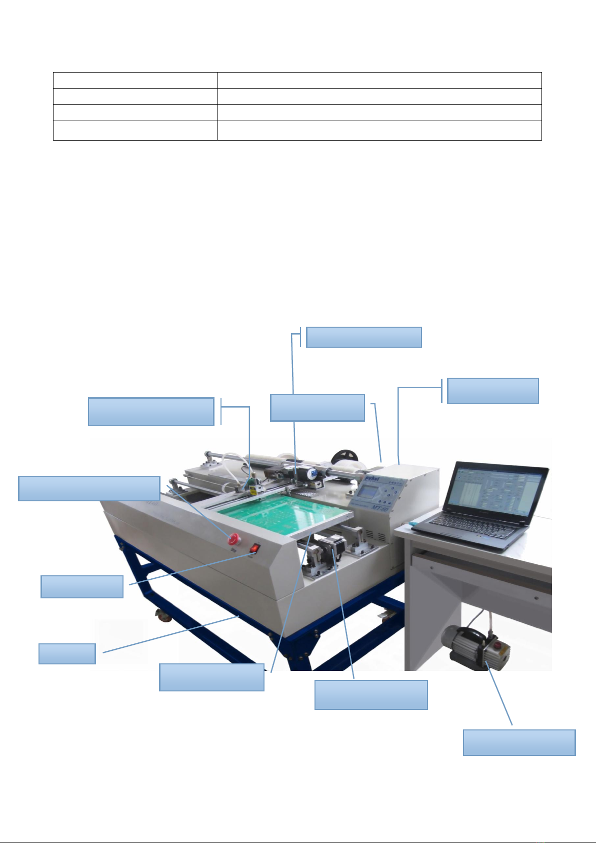
Machine Appearance
Suction Mechanism
Pushing Mechanism
Spindle motor -S
Control cabinet
Emergency stop switch
Power switch
Circuit board tray
Stents
The Motor of X-axis
Vacuum pump
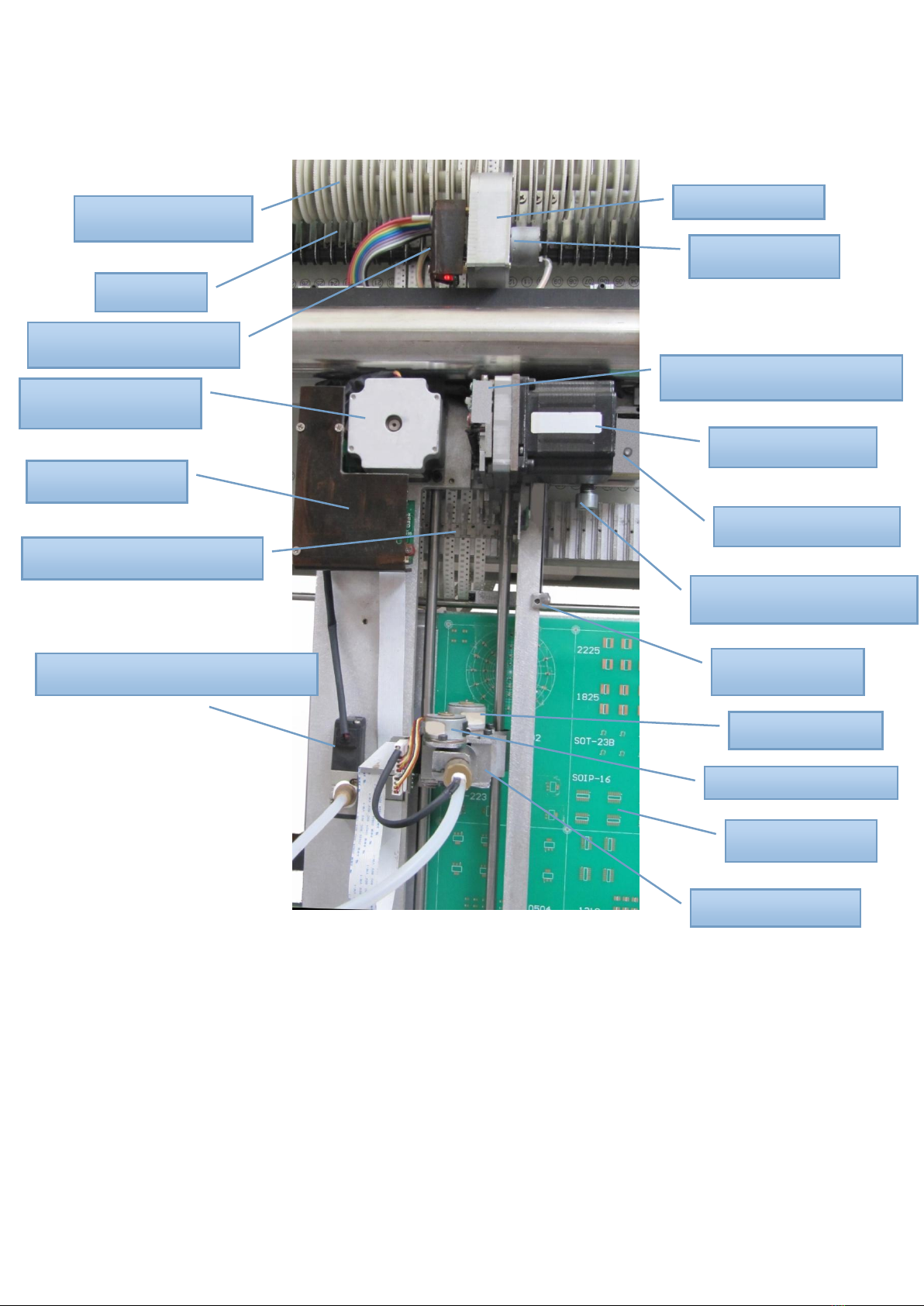
Waste recycling gear
Idler pulley
Take-up motor driver board
The Motor of Y-axis
Adapter plate
The Reed for press the feed
Vacuum suction nozzle solenoid valve
Take-up gear box
Take-up motor C
Pushing motor CAM mechanism
Pushing feed motor T
Pushing to adjust seat
Pushing feed adjustment bolts
Leak hunting base
A rotary motor Q
Pick and place motor Z
Circuit board tray
Absorb feed skeleton
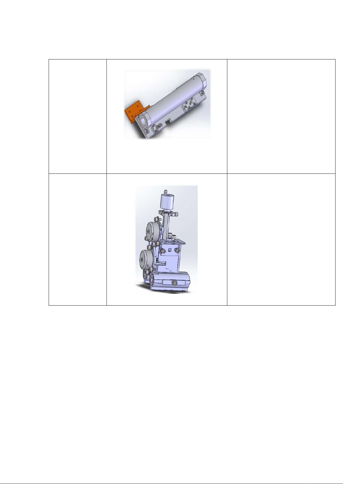
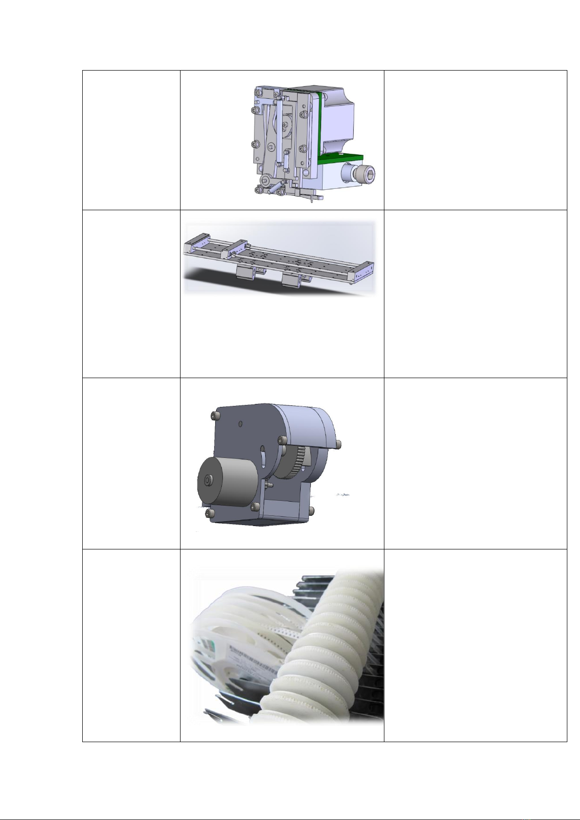
The overall structure
Spindle
motion
components
1The spindle drive motor S
2The mounting plate for S-axis motor
3The limit switch for S-axis motor
4The main orbital axis
5The bearing of S-axis
6The bearing pedestal of S-axis
7The casing of S-axis
8The slab of S-axis
9Synchronous belt
10Synchronous belt clamp mechanism
Suction
Mechanism
1Absorb feed skeleton
2Pick and place mechanism
3Rotating mechanism
4The limit switch for Z-axis
5The pick and place drive motor Z
6Rotate the drive motor Q
7Suction nozzle component
Pushing
Mechanism
1Pushing feed motor T
2Pushing CAM mechanism components
3The limit switch T
4Pushing the needle
5Pushing feed motor install L plate
6Eccentric shaft sleeve
7Rack
8Gear shaft
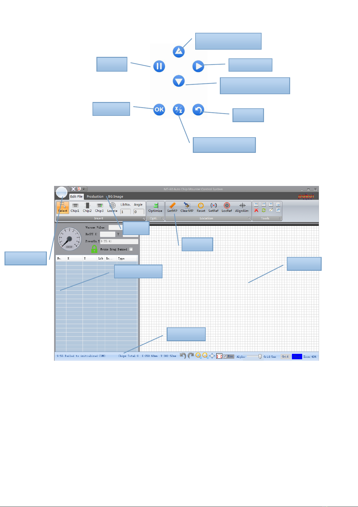
The X-axis
motion
mechanism
1The pallet drive motor X
2 Circuit board positioning bracket
3The pallet track bearing
4The pallet slider
5Pallet orbit X -axis
6The limit switch for X-axis
7Synchronous belt for X-axis
8Synchronous belt clamp mechanism
9 Spring retaining seat
10 Compression spring
11 Fastening bolts
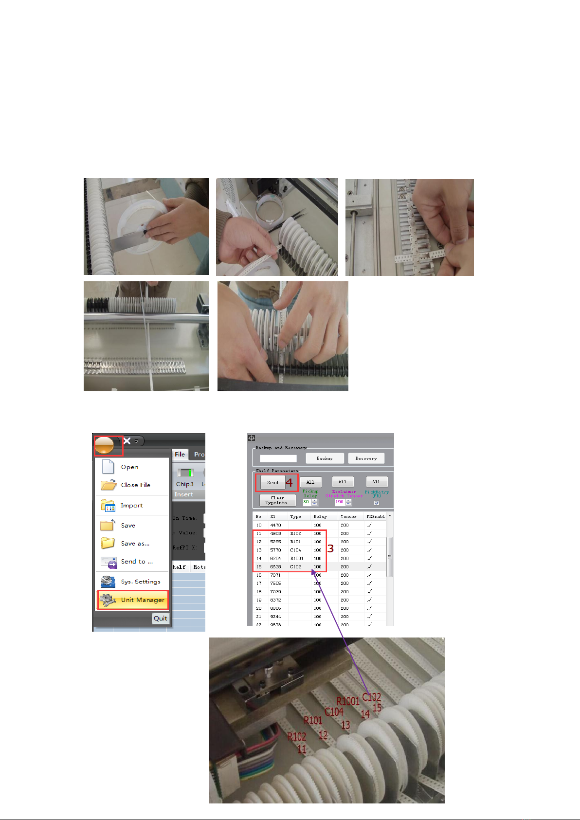
Waste
recovery
mechanism
1Closed with gear box
2Take up gear assembly
3Take up motor
4Take up motor drive circuit board
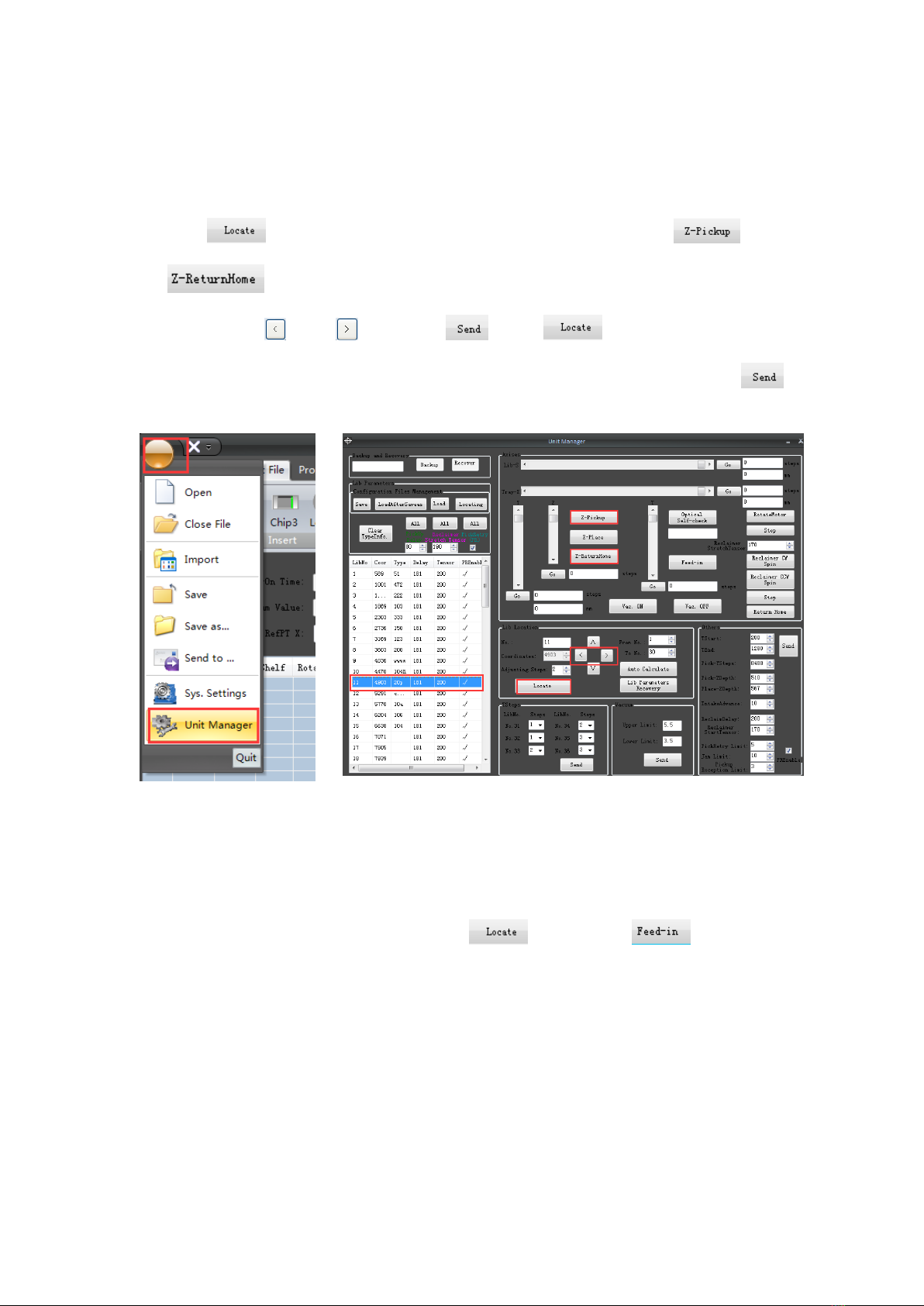
Rack
1 Tray tora
2 Tray pin
3Wast recycling gear
4Guide wheel

SMD
pressure
seat
1SMD pressure seat
2Binder reed
3Discharging pressure rod
Installation
1 Select the appropriate operating space for placing mounter.
2 Place it in a dedicated support shelf
3 -Access to the power supply and gas supply
-Access to the power supply on the INPUT socket labeled
-Access to the vacuum pump power on the socket labeled
-Access to the gas pump source from the interface success of auxiliary
control cabinet
The Test and Operation security essentials
1Don’t hinder the moving parts when the machine is moving
2Don’t push the moving parts when the machine stop
3Make sure that the terminal connection is good
4After power off, please again after boot in 20 seconds
5Don’t insert the other equipment into the power socket
6An emergency,press the red stop switch,system power is disconnected
Operation panel
1Front panel
A: Emergency stop switch
Press the switch, the machine stop any ongoing action.
Press the switch clockwise, button pop-up, machine resets, the shaft back to
the origin position
B: Power switch
Control the electrical source on and off
2Main panel
A:Liquid crystal display
B:Keys
Software panel
The mouse pointer
move up
Continue
The mouse pointer
move up
Pause
Confirm
The tray in and out
Return
Main menu
tab
Element list
Toolbar
Plot area
Status bar

Unit manager panel/ Parameter Interface
System Parameters Setting Interface
Backup
recovery
zone
Shelf
parameter
Shelf
landing
Shelf
location
Other
parameter
adjustment

Operation 1 —— Connect with computer
1. Connect MT-60 with computer by using RS232wire,open the control software, turn on the
power of MT-60.
2. Click “main menu”- “system parameter, you will see “system parameter setting dialog box”,
click serial port, you will see the current name of the serial port.
3. Select the serial port which match with RS232 wire.
4. Click OK, you will see the notice information in the bottom left corner of page。
5. At this time, Press “OK”at MT-60 operation panel, start to connect with computer, it
connect successfully when MT-60 operation page show “already connected with computer”
Operation 2 —— Parameter Adjustment
1.Install Feeders
Feeders NO 1-10 suit for diode, triode with plastic feeders. 31-34 suit for
12mm components,35-36 suit for 16mm components. The others suit for 8mm
components.
2.entryformation of feeders
Click main menu- Unit manager, entry the information of feeders.
3. Check feeders coordinate
Checking purpose: make nozzle locate in the middle of component
between left and right.
Click ―main menu‖–―Unit manager‖, click the number of checked feeder,
click , the nuzzle will move to the feeder, click and
, check whether the nuzzle locates in the middle of component.
If not, click and , then click , click again, the nuzzle wiil
move the new coordinate, check again to confirm the position. Click
after adjusted.
check pick- Ysteps
Checking purpose:make nozzle locate in the middle of component
between before and after.
Select any a feeder number, click , then click to push a
component, coil the skin manually. Then copy the data of Ysteps.
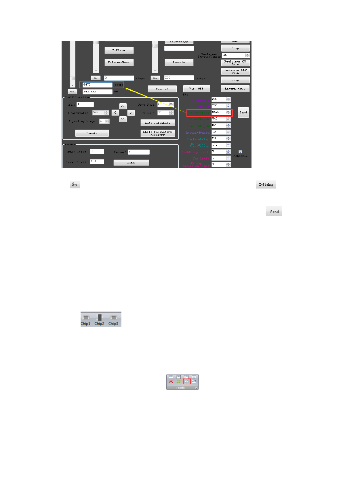
Click , the nuzzle will be moved over the component. Click , the
nuzzle lands on the component, check whether the nuzzle locates in the
middle of component. Copy the data to entry the pick Y steps., click to
save data.
Operation 3 —Create placement data document
(Create coordinate )
1. Basic Operation
a. components edit
1). Place component
Click to choose a component type, click on the left side of
the mouse for placing component in the plot area.
Tips: press the space bar to change the direction of rotation before placing;
press F2 bar to change 90 degree of rotation. Click on the right side of mouse
for quitting placing components state.
2) Copy and paste
Select the copy components, click , select any component as the
aim point, then move mouse to the paste point, click mouse to finish.
b. Set mark point
Purpose: find the corresponding coordinate, which corresponds to one point of
PCB in the plate.
Steps:
1. Place PCB in the plate;
2. Click , move mouse to the plot area, the mouse pointer changes
.
3.When move mouse or arrow keys, the nuzzle will be moved. Push the
space bar, the nuzzle lands on the PCB. Loosen the space bar, the nuzzle
rises.
4. Select a component as aim component, move mouse to make nozzle land
in the center of aim component. Press Enter bar, the mouse pointer changes
blue.
5. Press ESC bar to quit Mark state.
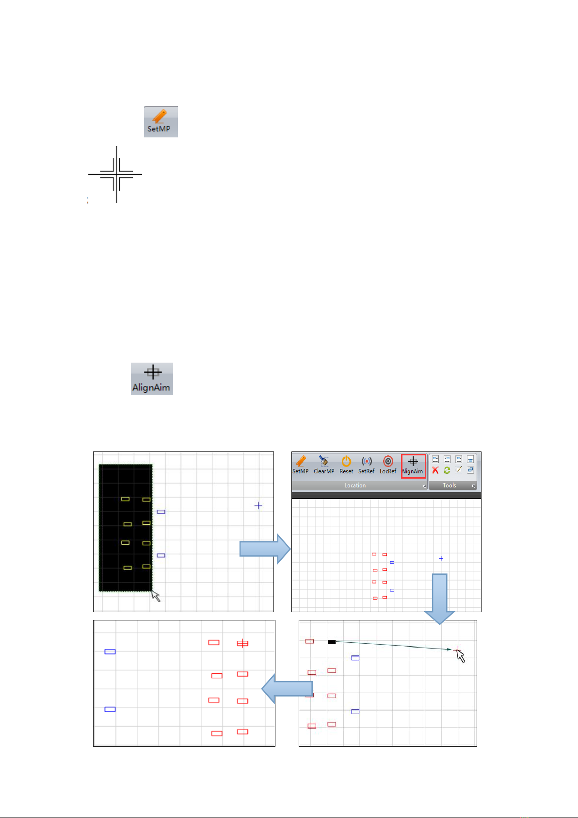
c. Align aim
1. Select all need to move components.
2. Click , click the aim component, it changes black.
3.Click the blue mark point, all the need to move components will be moved
to the new area.
4.Press ESC to quit align aim state.
2.Create placement data document
There are 3 types to create placement data document. Mark every point,
import PCB coordinate document, Mark printer scan.
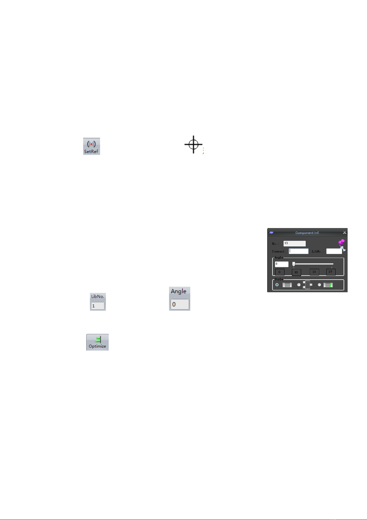
Operation 4—Set reference point
a. Mark point as the reference point of PCB in the plot area (via hole, pad holes,
etc)
b. Click , mouse pointer changes ,click on the left side of mouse to
set reference point.
c. Select the reference point, move to the mark point by align aim.
Operation 5—Entry information of component
1. Basic operation
a. edit a single component
In the edit file tab, double-click the component to bring up a
formula bar of component. Left-click on any whitespace to quit.
b. edit multicomponent
Select all the same type components, fill in the feeder number
then click to edit type. Click to edit angle.
2.Optimize mounting sequence
1. Click after finishing edition to check whether the document is
correct. It there is tip as below, please check the component number. It need
you to fill type in the Shelf parameter.
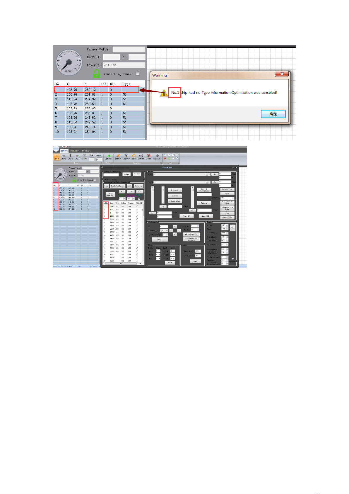
2. After optimizing, click main menu—save, the placement document is saved
on computer.
3.click main menu—transform, select the block number to save in the machine.
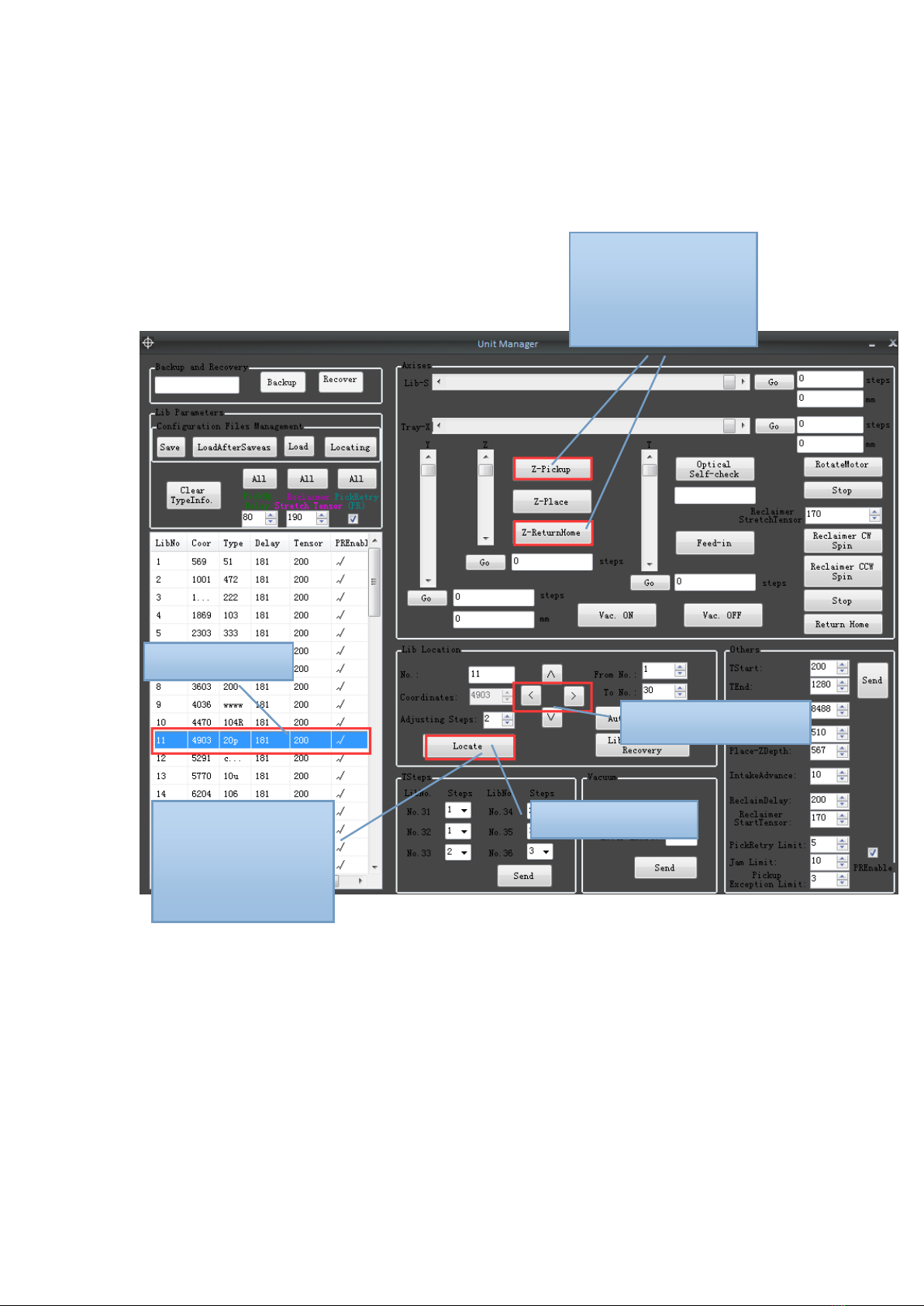
Fast learning how to operate
Unit Manager
1、Shelf Location
① Select Shelf
②click ―locate‖
③click ‖Z-pickup‖&
―Z-ReturnHome‖, see
the nozzle position on
chip
④adjust ―coordinates‖
⑤click ―locate‖,
repeat③④,until the
nozzle is in the centre
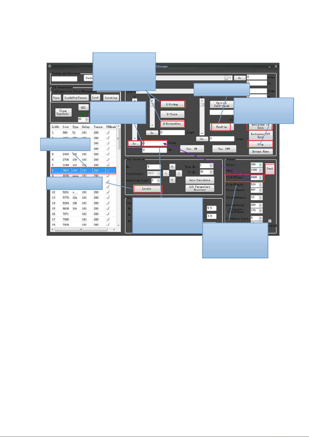
2、Pick-Y adjustment
MT-60 operation (not connect with computer)
Feeders in reserve
1. MT-60 has ten feeders in reserve.
⑧add/reduce the step
numbers, make sure the
nozzle in the centre of
chip
①Select Shelf
②click ―locate‖
③click ―Feed-in‖
④click ―Reclaimer
CW Spin‖ then ―Stop‖
⑤copy pick-ysteps
here ,then click “go”
⑦click ‖Z-pickup‖&
―Z-ReturnHome‖, see
the nozzle position on
chip
⑨Put the new step
numbers back to this
―Pick-YSteps‖, then
click ―send‖

Feeders
Main feeders number
Feeders in reserve number
8mm
9
49
10
50
11
51
12
52
13
53
14
54
15
55
16
56
12mm
31
33
32
34
2. Put same components at main feeder and feeder in reserve, when the
components at main feeder run out, MT-60 will continue to pick same
components from feeders in reserve.
Production (Pick and Place)
一、Turn on the power
二、Press to Offline operation ,press ,select placement file
三、press ,select file,press ,press ,check if nozzle is in the
center of reference point,if not,press adjust nozzle in the center,
press ,start mounting。
四、When mounting, press to stop mounting ,press continue
mounting,press return home。
If display ―blockage",please check machine as below.

State of machine
Operation
Run out of components
No
reserve
feeders
Change new components stack, then
press
Reserve
feeders
Press to continue place in
reserve feeder
There are still many
components.
Check whether there is something wrong with
machine, then press to continue
8mm/12mm/16mm Multi place
1. There are 2 models to mounting. They are multi and single to place.
In the multi model, It can be mounted 8/12/16mm once, not need to change
nuzzle.
In the single model, It need to change nuzzle.
2. The process of single model:
a. MT-60 will be pause when it
mounting all 8mm components, It will
move to open area at this time.
b. adjust bolt(8mm is in A,12mm is in
B,16mm is in C)
c. change the suitable nuzzle
d. press continue mounting.
Table of contents


