www.pulsar.pl HADOC2048B GREEN POWER plus
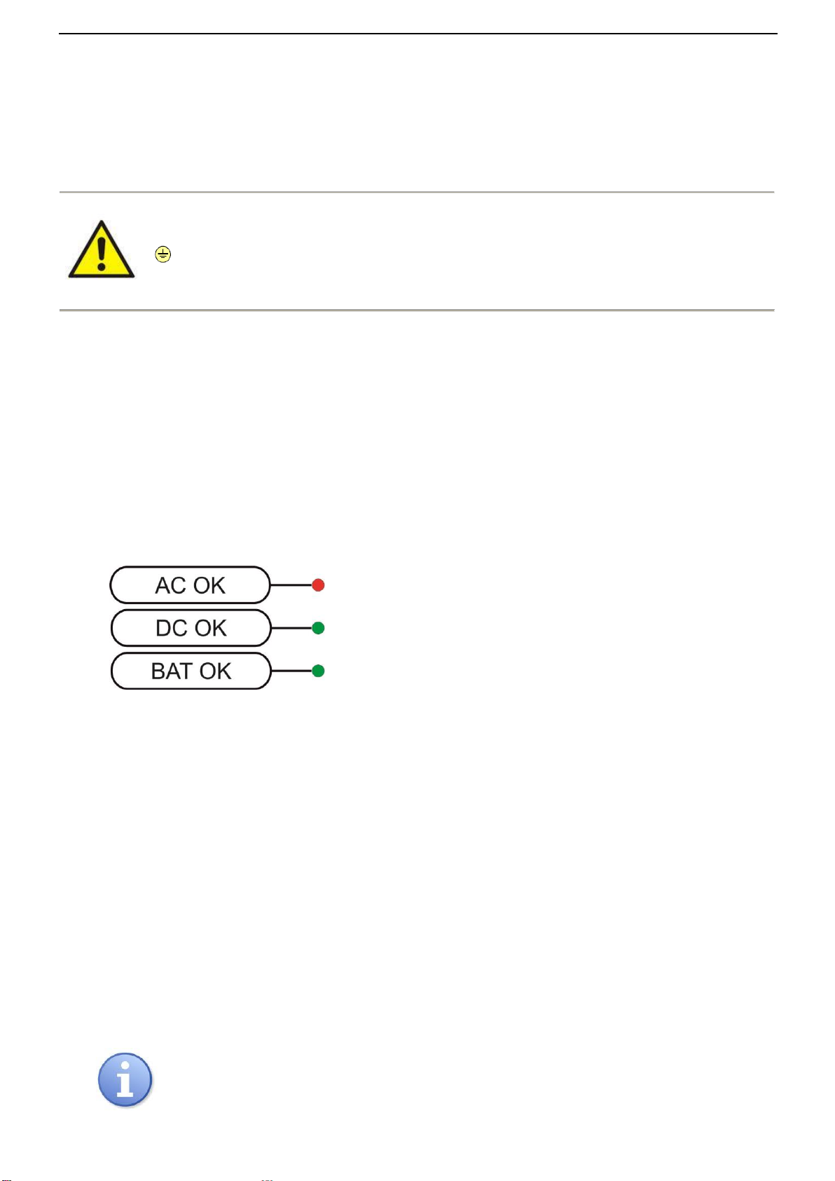
RED LED:
on –the PSU is supplied with 230V AC
off –no 230V AC supply
GREEN LED:
on –DC voltage in the AUX output of the PSU
off –no DC voltage in the AUX output of the PSU
on –PSU’s voltage UBAT > 46V
off –PSU’s voltage UBAT < 46V
2.2 Installation procedure.
1. Before installation, cut off the voltage in the 230V power-supply circuit.
2. Mount the PSU in a selected location and connect the wires.
3. Connect the power cables (~230Vac) to L-N clips of the PSU. Connect the ground wire to the clip marked by the
earth symbol PE (PSU module connector). Use a three-core cable (with a yellow and green PE protection wire) to
make the connection. Lead the cables to the appropriate clips through the insulating bushing of the connection
board.
The shock protection circuit shall be performed with a particular care, i.e. the yellow and
green wire coat of the power cable shall stick to one side of the terminal - marked with
‘‘symbol on the PSU enclosure. Operation of the PSU without the properly made and fully
operational shock protection circuit is UNACCEPTABLE! It can cause a device failure or an
electric shock.
4. Connect the receivers’ cables to the terminals V+ (+), COM(-) of the PSU module.
5. Connect the power (~230V)
6. Check the PSU output voltage:
- the PSU voltage without load should amount to U=54V DC
7. Connect the battery (mind the colours):
- battery output (+V): BAT+ cable / red,
- battery output (0V): BAT –cable / GND / black.
8. Check the optical indication of the PSU status: LED (green LED on the power supply module).
9. After installing and checking proper working, the enclosure can be closed.
3. Operating status indication.
3.1 LED indication of operating status.
The PSU is equipped with 3 diodes on the front panel:
Moreover, the PSU is equipped with 3LEDs on the PCB board:
- red LED (Fig.2, element 1) normal status (AC power): permanently illuminated. AC power absence is
indicated by the AC diode going out.
- green LED (Fig.2, element 2) indicates DC power at the PSU output. Under normal status the diode is
permanently illuminated. In case of a short circuit or an overload, the diode is off.
- green LED (Fig.2, element 3) indicates battery voltage level. Under normal status (UBAT > 46V) the diode is
permanently illuminated. In case of decrease of battery voltage (UBAT < 46V) the diode is off.
3.2 Technical outputs
The PSU has indication outputs:
EPS - absence of AC supply output:
- OC type output that indicates AC power loss. Under normal status, with 230V AC supply, the output is connected to
ground (L level –0V). In case of power loss, the PSU will switch the output into high impedance state hi-Z after
approx. 10s.
- relay output indicating the absence of AC supply. In case of power loss, the PSU module will switch the relay
contacts.
CAUTION! In Fig.2. the contact set in the potential-free status corresponds to a state with no AC
power (AC power failure).