manuals.online logo
Brands
  1. Home
  2. •
  3. Brands
  4. •
  5. Pulsar
  6. •
  7. Power Supply
  8. •
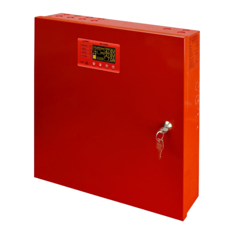
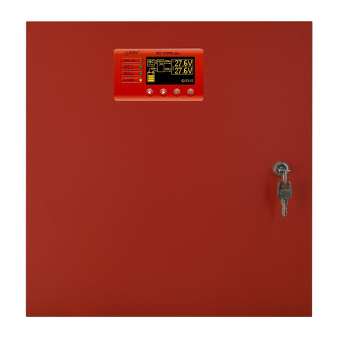
  9. Pulsar PSDCSEP-12V4x1A User manual

Pulsar PSDCSEP-12V4x1A User manual

1
USER MANUAL
EN
Edition: 1 from 10.02.2022
Supersedes edition:
PSDCSEP-12V4x1A
v1.0
PSDCSEP 12V/4A/4x1A power supply with 4 separated
outputs
2
Features:
supply voltage ~100 - 240 V
power supply output 4x 12VDC/1A
high efficiency (up to 82%)
4 independent, galvanic isolated outputs
independent output voltage adjustment 12 –15 V DC
4 independent outputs protected by 1A fuses
optional equipment: mounting plate DIN4
LED optical indication
protections:
SCP short circuit protection
OVP overvoltage protection
surge protection
OLP overload protection
warranty –2 years from production date
TABLE OF CONTENTS:
1. Technical description.
1.1. General description
1.2. Block diagram
1.3. Description of PSU components and connectors
1.4. Specifications
2. Installation.
2.1. Requirements
2.2. Installation procedure
3. Operating status indication.
4. Operation and use
4.1. Overload or short circuit of the PSU module output.
4.2. Operation of the PSU OVP system
5. Maintenance
1. Technical description.
1.1. General description.
PSDCSEP-12V4x1A stabilised power supply is intended for supplying power to cameras or other devices that
require stabilised voltage of 12V DC. The PSU has 4 independent outputs with voltage adjustment within the range of
12-15VDC/4x1A, ensuring compensation of voltage drops in CCTV installations. The outputs of the PSU are galvanic
separated and protected with fuses. A failure (a short circuit) in the output circuit makes a fuse blow and disconnects the
circuit from the DC power supply (+U).
Table 1. Displaying parameters of the power supply:
Model
Number of
outputs
Output voltage AUX
Output current
PSDCSEP-12V4x1A
4
12 V (12 –15 V)
4x 1A
.
1.2. Block diagram.
Fig.1. Block diagram of PSU.
3
1.3. Description of PSU components and connectors.
Table 2. Elements and connector of PSU (see Fig. 2)
Element no.
Description
[1]
Main fuse
[2]
L-N power supply connector 230 V AC, PE protection connector
[3]
VADJ, potentiometer, output voltage adjustment 12 –15 V DC
[4]
LED (green) indicating presence of voltage at output of the PSU
[5]
Fuse in AUX circuits
[6]
AUX2 output
[7]
AUX3 output
[8]
AUX4 output
Fig. 2. View of power supply module PSDCSEP-12V4x1A
1.4.Specifications.
- PSU parameters (tab. 3)
- operation safety (tab. 4)
- operating parameters (tab. 5)
Table 3. PSU parameters.
Model
PSDC-12V4x1A
Power supply
~ 100 –240 V; 1A; 50/60 Hz
Inrush current
40 A
PSU power
48 W max.
Output current
4x 1 A
Efficiency
82%
Output voltage (factory settings)
12 V DC
Adjustment range UAUX
independent for each output: 12 –15 V DC
Ripple voltage
50mV p-p max.
Short circuit protection SCP
4x F 1A glass fuse fast blow
Overload protection OLP
105 –150% PSU power, automatically recovered
Surge protection
varistors
Over voltage protection OVP
>19V (automatic recovery)
Protection in 230 V circuit
glass fuse T5A
LED operation indication
- LEDs on PCB of power supply unit: The green L1...L4 LEDs indicate the power
4
supply status on the outputs: AUX1...AUX4
Enclosure dimensions
(LxWxH) [±2mm]
204x141x52
Fixing
(L1xW1xL2xW2)
155,5x64x18x51,5
Net/gross weight
0,56 / 0,61 kg
Connectors
Power supply: 0,5 –1,5 mm2(AWG 26 –16)
Notes
Convectional cooling
Fig. 3 Dimensions of the power supply unit.
Table 4. Operation safety.
Table 5. Operating parameters.
2. Installation.
2.1. Requirements.
PSU is to be mounted by a qualified installer, holding relevant permits and licenses (applicable and required for a
given country) for 230 V in and low-voltage installations. Unit should be mounted in confined spaces, in accordance, with
normal relative humidity (RH=90% maximum, without condensing) and temperature from -10°C to +40°C. The PSU shall
work in a vertical position that guarantees sufficient convectional air-flow through ventilating holes of the enclosure.
The unit should be mounted in a metal enclosure (cabinet) in a vertical position so as to ensure free, convection
air flow through the vents. In order to meet the EU requirements, follow the guidelines on: power supply, enclosures and
shielding: - according to application.
As power supply is designed for a continuous operation and is not equipped with a power-switch, therefore, an
appropriate overload protection in power supply circuit should be provided. Moreover, the user shall be informed about
the method of unplugging (most frequently through separating and assigning an appropriate fuse in the fuse-box).
The electrical system shall follow valid standards and regulations.
2.2. Installation procedure.
CAUTION!
Before installation, cut off voltage in 230 V power-supply circuit. To switch power off, use an
external switch, in which distance between contacts of all poles in disconnection state is not less
than 3mm.
Protection class EN 62368-1
I (first)
Electrical strength of insulation :
- between input and output circuits of the PSU
- between input circuits of the PSU
- between input circuit and protection circuit
- between output circuit and protection circuit
2500 V AC min.
2500 V AC min.
1500 V AC min.
500 V AC min.
Insulation resistance:
- between input circuit and output or protection circui
100 MΩ, 500 V DC
Operating temperature
-10ºC...+40ºC
Storage temperature
-20ºC...+60ºC
Relative humidity
20%...90%, without condensation
Vibrations during operation
unacceptable
Impulse waves during operation
unacceptable
Direct insolation
unacceptable
Vibrations and impulse waves during transport
According to PN-83/T-42106
5
It is required to install an installation switch with a nominal current of 6 A in power supply circuits outside
power supply unit.
1. Mount the PSU in a selected location and connect the wires.
2. Connect power cables (~230 V) to L-N clips of PSU. Connect ground wire to clip marked by earth symbol . Use a
three-core cable (with a yellow and green protection wire) to make connection ). Lead the cables to the appropriate
clips through the insulating bushing of the PSU.
Shock protection circuit shall be done with a particular care: yellow and green wire coat of power cable
should be connected to terminal marked with the grounding symbol on PSU enclosure. Operation of PSU
without the properly made and fully operational shock protection circuit is UNACCEPTABLE! It can cause
damage to equipment or an electric shock.
3. Switch on 230 V supply. LEDs on power supply PCB should be ON.
4. Check output voltage and adjust if necessary using right potentiometer.
5. Disconnect the PSU from the mains and make the rest of the connections - connect wires to the AUX1...AUX4
connectors.
6. Once the tests and control operation have been completed, close the enclosure/cabinet.
3. Operating status indication.
The power supply unit features LED status indication. Presence of voltage at each output of the PSU is indicated by the
green LED nearby each outputs fuse. Failure (fuse damage) is indicated by shutting down green LED nearby appropriate
outputs fuse on the PSU module.
4. Operation and use.
4.1. Overload or short circuit of the PSU module output.
The AUX1÷AUX4PSU outputs are protected against short circuit by glass fuses. Activation of the protection (glass fuse
blowing) is indicated by shutting down green LED nearby appropriate outputs fuse on the PSU module. In case of damage,
replace the fuse (compatible with the original).
4.2. Operation of the PSU OVP system.
If the OVP system is activated, the output voltage is automatically cut off. Operation is resumed automatically.
5. Maintenance.
Any and all maintenance operations may be performed following the disconnection of the PSU from the power
supply network. The PSU does not require performing any specific maintenance measures, however, in the case of
significant dust rate, its interior is recommended to be cleaned with compressed air.
WEEE MARK
According to the EU WEE Directive –It is required not to dispose of electric or electronic waste as
unsorted municipal waste and to collect such WEEE separately
Pulsar sp. j.
Siedlec 150, 32-744 Łapczyca, Poland
Tel. (+48) 14-610-19-40, Fax. (+48) 14-610-19-50
e-mail: biuro@pulsar.pl, sal[email protected]
http:// www.pulsar.pl, www.zasilacze.pl
Other Pulsar Power Supply manuals

Pulsar 276V/7A/2x40Ah/LCD User manual

Pulsar

Pulsar 276V/7A/2x40Ah/LCD User manual

Pulsar DIN 1220 User manual

Pulsar

Pulsar DIN 1220 User manual

Pulsar PSCU 04344SEP User manual

Pulsar

Pulsar PSCU 04344SEP User manual

Pulsar AWO 205PU User manual

Pulsar

Pulsar AWO 205PU User manual

Pulsar AWZ 224 User manual

Pulsar

Pulsar AWZ 224 User manual

Pulsar HPSB 3512B User manual

Pulsar

Pulsar HPSB 3512B User manual

Pulsar PSUPS10A12C User manual

Pulsar

Pulsar PSUPS10A12C User manual

Pulsar GREEN POWER CCTV PoE POE044816 User manual

Pulsar

Pulsar GREEN POWER CCTV PoE POE044816 User manual

Pulsar AWZ 101 User manual

Pulsar

Pulsar AWZ 101 User manual

Pulsar PSBEN 10A12E/LCD User manual

Pulsar

Pulsar PSBEN 10A12E/LCD User manual

Pulsar MSRK 13,8V/1A User manual

Pulsar

Pulsar MSRK 13,8V/1A User manual

Pulsar GREY POWER plus AWZ 222 User manual

Pulsar

Pulsar GREY POWER plus AWZ 222 User manual

Pulsar PSDC09125T User manual

Pulsar

Pulsar PSDC09125T User manual

Pulsar HPSB 20A12E User manual

Pulsar

Pulsar HPSB 20A12E User manual

Pulsar Black Power PSBEN 5012E User manual

Pulsar

Pulsar Black Power PSBEN 5012E User manual

Pulsar SWB-60 User manual

Pulsar

Pulsar SWB-60 User manual

Pulsar PSBS 10A12C User manual

Pulsar

Pulsar PSBS 10A12C User manual

Pulsar PSCC20700 User manual

Pulsar

Pulsar PSCC20700 User manual

Pulsar PSDCB05125C User manual

Pulsar

Pulsar PSDCB05125C User manual

Pulsar PSBEN 10A12C/LCD User manual

Pulsar

Pulsar PSBEN 10A12C/LCD User manual

Pulsar PSP48005 User manual

Pulsar

Pulsar PSP48005 User manual

Pulsar HPSBB 0212 User manual

Pulsar

Pulsar HPSBB 0212 User manual

Pulsar PSDC 16128 User manual

Pulsar

Pulsar PSDC 16128 User manual

Pulsar PSBEN 10A12E/LCD User manual

Pulsar

Pulsar PSBEN 10A12E/LCD User manual

Popular Power Supply manuals by other brands

TDK-Lambda SWS-L Series instruction manual

TDK-Lambda

TDK-Lambda SWS-L Series instruction manual

Allftek AF Series user manual

Allftek

Allftek AF Series user manual

Broncolor SENSO A2 operating instructions

Broncolor

Broncolor SENSO A2 operating instructions

GAMDIAS KRATOS BRONZE M1-550W Quick installation guide

GAMDIAS

GAMDIAS KRATOS BRONZE M1-550W Quick installation guide

Mac Victor MVP-2KS Installation and operating manual

Mac Victor

Mac Victor MVP-2KS Installation and operating manual

DuraComm RLP-2024-BBSCLVD owner's guide

DuraComm

DuraComm RLP-2024-BBSCLVD owner's guide

Thermaltake TR2 RX 700w user manual

Thermaltake

Thermaltake TR2 RX 700w user manual

HP 711A user guide

HP

HP 711A user guide

AgfaPhoto PPS 600Pro user manual

AgfaPhoto

AgfaPhoto PPS 600Pro user manual

National Instruments RMX-4120 user manual

National Instruments

National Instruments RMX-4120 user manual

Skyrc eFuel 230W instruction manual

Skyrc

Skyrc eFuel 230W instruction manual

M-system W2DYH instruction manual

M-system

M-system W2DYH instruction manual

Vimar by-me Eikon 20541 quick start guide

Vimar

Vimar by-me Eikon 20541 quick start guide

Elettrotest TPS/M 1500 user manual

Elettrotest

Elettrotest TPS/M 1500 user manual

ADOR RK3000 manual

ADOR

ADOR RK3000 manual

Thermaltake Purepower W0328 user manual

Thermaltake

Thermaltake Purepower W0328 user manual

Cabletron Systems SmartSTACK ELS100-S24TX2M Quick installation guide

Cabletron Systems

Cabletron Systems SmartSTACK ELS100-S24TX2M Quick installation guide

VOLTCRAFT LSP-1205 operating instructions

VOLTCRAFT

VOLTCRAFT LSP-1205 operating instructions

manuals.online logo
manuals.online logoBrands
  • About & Mission
  • Contact us
  • Privacy Policy
  • Terms and Conditions

Copyright 2025 Manuals.Online. All Rights Reserved.