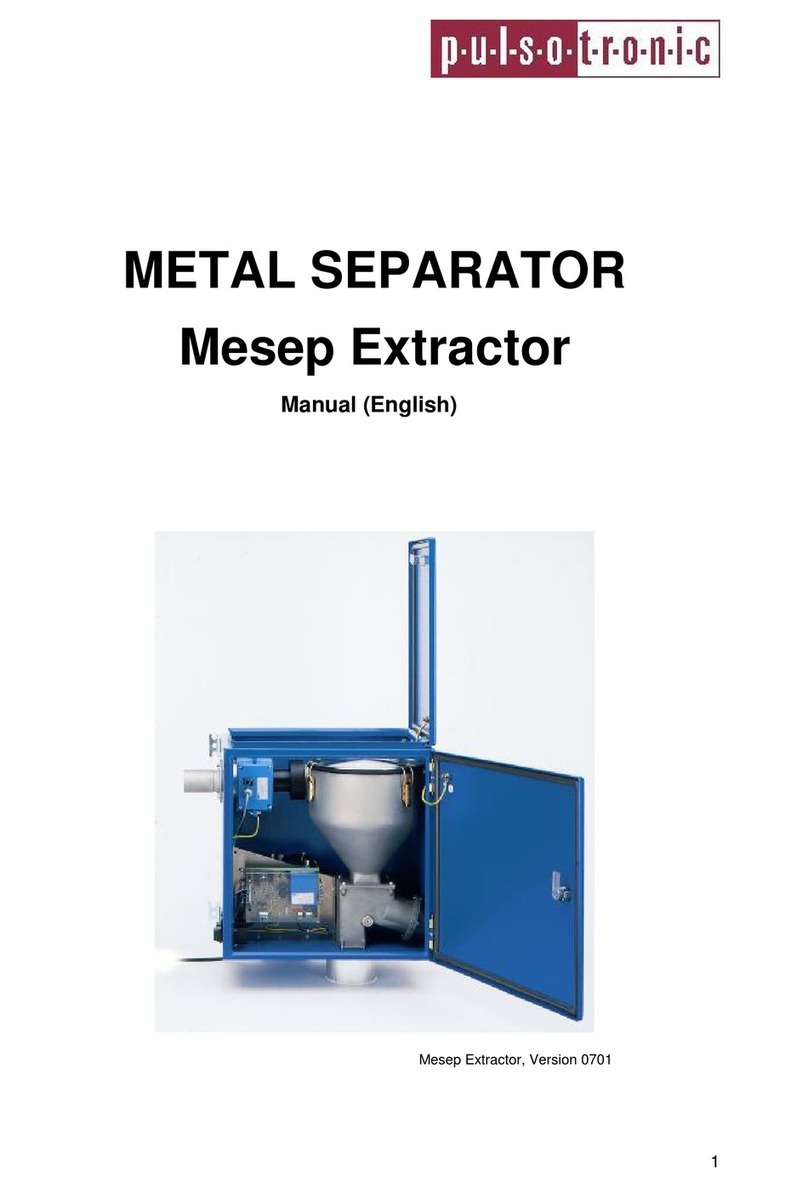
Pulsotronic MESEP VA digital 50 User manual

METAL SEPARATOR
MESEP® VAdigital 50/ 70
Manual
Project Name
Order / Project No.
Metal separator type MESEP VA digital70
The final outlookofthe units depends onthe different
features we offer.

2
1Contents
1CONTENTS..................................................................................................................................2
2GENERAL....................................................................................................................................3
2.1 INSTRUCTIONS FOR USE OFTHIS MANUAL..............................................................................3
2.2 GENERAL SAFETY INSTRUCTIONS...........................................................................................4
2.2.1 Explanation of the Symbols Used......................................................................................4
2.2.1 BASIC SAFETY MEASURES......................................................................................................5
3APPLICATION AND QUALIFICATION................................................................................6
3.1 USE FOR INTENDED PURPOSE..................................................................................................6
3.2 EXAMPLES OF APPLICATION ...................................................................................................7
3.3 OPERATING PRINCIPLE............................................................................................................7
3.3 MISUSE...................................................................................................................................7
3.4 OWNERS DUTY OF CARE.........................................................................................................8
3.5 FUNCTION .....................................................................................................................................8
3.5.1 Keypad...................................................................................................................................8
3.5.2 Key Functions......................................................................................................................10
3.5.3 Selection of Operation Variants..........................................................................................11
3.6 SENSITIVITY TABLE.....................................................................................................................12
3.7 THESEPARATINGDRUM ..............................................................................................................13
4OPERATING INSTRUCTIONS FOR THE METAL SEPARATORS................................14
4.1 Erection Instructions.......................................................................................................14
4.2 Connection Instructions..................................................................................................14
4.3 Operation Instructions....................................................................................................15
4.4 Failure Protection of the Metal Separator......................................................................15
5TECHNICAL CHARACTERISTICS......................................................................................16
6TECHNICAL DESCRIPTION.................................................................................................17
6.1 FRONT PLATE........................................................................................................................17
6.2 SELECTION OF OPERATION VARIANTS..................................................................................18
6.3 NOTES FOR THE VALUES OFSENSITIVITY ..............................................................................19
6.4 SORTING GATE .....................................................................................................................19
6.5 FUNCTION AND LIMITATIONS ................................................................................................19
6.5 PRODUCT EFFECTS - DISTURBING PRODUCT PROPERTIES.....................................................20
7. TRANSPORT.............................................................................................................................22
7.2 SAFETY INSTRUCTIONS FOR TRANSPORT AND ERECTION ......................................................22
8INSTRUCTIONS FOR ERECTION........................................................................................22
8.1 ERECTION AIDS ....................................................................................................................22
8.2 CONNECTORS........................................................................................................................23
8.3 SAMPLE OFAPPLICATION ......................................................................................................24
8.4 ELECTRICAL CONNECTION....................................................................................................25
8.5 PRINTED CIRCUIT BOARD .....................................................................................................28
8.6 FACTORY SETUP ...................................................................................................................29
8.7 QUICK REFERENCE ...............................................................................................................29
9. MAINTENANCE.......................................................................................................................30
9.1. GENERAL MAINTENANCE .....................................................................................................30
9.1.1 Repairs and Wearing parts - Important Notice...................................................................31
9.1.2 Removal of the Laminated-Paper Protective Tube..............................................................32
9.2 REGULAR INSPECTIONS.........................................................................................................32

3
10 TROUBLESHOOTING........................................................................................................33
11 ACCESSORIES.....................................................................................................................34
12 SPARE PARTS......................................................................................................................35
13. ANNEX...................................................................................................................................35
2General
2.1Instructions for Use of this Manual
This manual applies toMESEP® VA digital50/70
Manufacturer:
Pulsotronic GmbH& Co.KG
Neue Schichtstr. 14
09366 Niederdorf
Phone: 03 7296 / 930100
Fax: 03 7296/ 930 180
Edition: October 2004, v. 1.2
This manual contains all information required for operation of the equipment.
Prior to the first use ofthe metal detector, this manual must havebeen read
and understood byall people workingat or with the metal separator.
Particular attention hasto be paid to the SafetyInstructions.
The users manual is part ofthe metal separatorand has to be keptin such a
waythat is alwaysaccessible to the authorized personnel. In no case, parts of
this manual maybe removed. Amissingmanual or parts ofit, especiallythe
section onsafetyinstructions, must be replaced immediately.

4
Notice:
Pulsotronic GmbH &Co. KG does not grant implied warrantyforcommercial
qualityand suitabilityfor a particular purpose of application.
This document containscopyrighted information. WithoutPulsotronic GmbH &
Co. KGsprior permission, it mayneither becopied nor duplicated,translated or
digitallystored.
This documentation is not included in Pulsotronic GmbH &Co. KGs update
service. All rights includingthat ofmodificationofthis documentation are
reserved.
2.2General SafetyInstructions
2.2.1 Explanation of the Symbols Used
The followingsafetysymbols are used in this manual. Theyare to direct the
readersattentiontotheaccompanyingtext.
Danger!
This symbolindicates danger for life and health, or that
an important technical fact has to betaken into
consideration.
Danger!
This symbolindicates danger for life and health due to
electrical voltage.

5
2.2.1Basic SafetyMeasures
• Do not put your hand into theopenings of the metal separator. Mechanical forces
which maycause heavy injuries occur on switching of thepneumatic gate.
• Prior to anymaintenanceworks, disconnect theequipment from compressed air
and power. Make surethat nobodycanreconnect compressedair andpower
during themaintenance works.
• Never put the metalseparator intooperation without the supplied safetydevices.
This isof particular significance for the protective gridabove themovable
components.
• Instantlyshut-off theequipment if safetydevices are not functioningproperlyor
are damaged.
• In caseof failures duetowearingor ageing, their reasons have to beeliminated
immediately.
• Schedule sufficient regular maintenanceintervals.
• Always observe thesafetyinstructionsfixed totheequipment. Theyhelp toavoid
hazards. Innocase, these instructionsmaybe removed.
• Do not put themetal separator intooperation if
• not havingreceived complete instruction bythe owner,
• you have not studied thismanual completely,
• have not understoodthismanual completely
• Errorsin operation maylead toseriousdamageof healthand property.
Danger!
Avoid touching the electronic p. c. board
Prior to wiring the electronic with peripheral equipment, disconnect the
unit from compressed air and power supply.This will helpyou to avoid
short circuits.
Static charges must be discharged before starting working.

6
3Application and Qualification
3.1Use for Intended Purpose
The MESEP® VA digital removes metallic contaminations from bulkmaterials.
These materials, for example, can be plastic granules, drypowder, rice or similar
productsfrom different industries.
Free-fall metal separation:
The unit is integrated inthe existingconveying system. To guaranteereliable
separation, the material must not bedroppedinto the device fromaheight ofmore
than 600mm.
Duringthe separation process,it happens that also aminor quantityof the good
material is discharged.
To guarantee the units reliable work,anumber asecondaryandoperating
conditions haveto be observed. This manual deals with those subjects. That is the
reason why it is strictly requiredto studythis manual to guarantee perfectand
reliable operation.
Metal separators are used everywhere where metallic contamination must be
removed fromfreelyfallingbulkmaterials in the product flow.With highsensitivity
and reliability, our type 8217 metal separators react to andseparatemetals like
steel / high-grade steel
iron
aluminium
copper
zinc
brass
nonmagneticpreciousmetals
Material-coated metallic particles are detected safelyseparated, aswell.
This resultsin awide application range for themost different industries:
plastics industry
foodstuff industry
animal feedindustry
pharmaceutical industry

7
semi-finished and finished products industries
etc.
The 8217 type metal separators are used amongstothers at places where long
equipmentrunningtimes are required. The highsensitivityofthe separators
guarantees shortestpossible machine downtimes and metal-free final products
accordingto nominal sensitivity.Especiallythere where the final products cost
effectiveness comesfrom the quantity, the unit pays for itselfwithin short time.
3.2Examplesof Application
Metal separatorsareused
at the endof a cyclone separator
at the endof a downpipe
at the outlet of a granulatingcrusher
at all material dumpingplaces
as aportable equipmentto feed multiple machines (onlyone unit formore
than onemachine)
3.3Operating Principle
The material to bechecked flowfrom aunit hopper, aflanged pipeline or afeeder
into the metal separator. The separator includes metal detectingcoil, followed bythe
sortinggate. Thesorting gate includes apneumatic valve.
As longas metallic particles are not detected, the material flowsalmost vertically
throughtheseparator via theOKduct for further processing(fig. 1).
Ifthe ring sensor detects metal, the valvein the sortinggate changestothe NOT
OK ductand separatesin this waythe contaminated material fromthe good one.
The separating time is adjustable (potentiometer on the electronic circuit board) from
200 milliseconds to one second, depending on themetallic participle portion and the
flowspeed of the material.
3.3Misuse
It is a misuse to use theMESEP© digital metalseparatorforotherpurposes
than described in section3. Especially, the following is prohibited:
• modifyingor removing of themetal separators safetydevices
• usingthe metal separator for unapproved purposes

8
• modifyingthe metal separator without permission byPulsotronic SKS GmbH
&Co. KG to fortheuse for other purposes. Consider that aftera
modification you mayberegardedas manufacturer ofthemetal separator-
with all guarantyconsequences.
3.4OwnersDutyof Care
The MESEP© digital metal separator was designed and producedaccordingto
harmonized digitals. It is in accordance with the latest state oftechnology, and it
provided maximum safety.However, duringoperation this safetycan onlybe
achieved if all required measureshad been taken. It is within the owners dutyof
care to determine these measures, and to checktheir implementation.
• In particular, the owner must guaranteethefollowing:
• the metal separator must onlybe used for itsintended purpose(refer to 3.1,
APPLICATION AND QUALIFICATION
• the metal separator mayonlybe used in properlyfunctioningcondition, and
particularlyits safetydevices must becheckedregularlyfor functioning,
• the operatingmanual must always be available in legible and completecondition,
• operation, maintenance and repairsareonlybe carried out byqualified and
authorized personnel,
• prior to the first puttinginto operation andthenin regular intervals, the personnel
must be instructedabout labour safetyandenvironmental protection, and has to
knowthis manual andthe safetyinstruction contained therein.
• all safetyand warning instructions fixed to the equipment maynot be removed
and must bekept in clearlylegible condition.
3.5 Function
This section informs about design and function of themetal separator.
TheMESEPdigital consistsof three functional sections:
• keypad (refer tochapter 5.1)
• ring detector with transmitter and receiver coils
• a pneumatic operatingseparating drum (refer tochapter 5.3)
3.5.1 Keypad
Thekeypad is at the outer side of theblue control box. Bymeans of it,
disturbancesareindicated byLEDs, andthesensitivitysetup is shown. All
important settings are made bykey-pressing. The keypad includes among
othersfour verticallyarrangedLEDs which showthe followingoperationstates.
• GreenLED OPERATION

9
the MESEP digital workswithout problems.
• Red LED „VALVE FAULT“
After thelast metal detection theseparatingdrum did not reach theend
position. TheMESEP digital can not separatethedetectedmaterial. As soon as
the separating drum switches perfect again after a further metal detection, the
error report goesout automatically.
Elimination of “VALVE FAULT“
• Put thereset key
• Check thecompressedair supplyand compressed air height
• Check separatingdrum on swinging
• Red LED RING FAULT
Indicatesa fault of ringcoil or evaluation electronics. After elimination of the fault,
the LED goesout automatically, and the device isreadyfor operationagain.
Elimination of “RING FAULT”
• Remove power conducting matters being trappedin theringcoil.
• Check electrical connections of thecircuit board.
• Inspect the metal separator visually.
• Press the reset key.
• Red LED PRESSURE FAULT
Indicates afault ofthe compressed-air supply.This is anextended function and not
implementedin thebasicvariant.
Elimination of PRESSURE FAULT
• Check thecompressed-air supply.

10
Notice: Apart of the inscription of thekeypad isexchangeable. Cautiouslyuse
tweezers to find thesmall gapat theright side of the keypad. Widenthe gap a little
and remove thelabel.
Everyunit comes with labels in German, English and French. Theunit is supplied
with labels in German. The labels in other languagesarein theoperatingmanual.
3.5.2 KeyFunctions
TheMESEP digital is set up byfour keys. It is not required to adjust potentiometers.
Therefore, putting theunit into operationis verysimple.
Thekeyfunctions are asfollows:
TEST
• Short manipulation effects metal indication. The separatingdrum switches brief
into theejection position. The functionserves to test the metal separator by key-
pressing. At thesametime, thefour LEDsshowthe currentlyselected sensitivity
value as a LED combination.
• Do holdingthe key. The separatingdrum switches into theejection position as
longasthekeyis beingpressed. This enablestakingof material samples from
the conveyingflow. Inthis way, dischargeof a dosingunit or mixer mounted on
the metal separator can be performed bykeypressing.
F1+
Short manipulation shows thecurrentlyselectedsensitivities for 5sec. (refer to
sensitivitytable, chapter 5.2). Longer pressingof F1+ increases the sensitivity
unless maximum sensitivitywas reached.
F2-
Short manipulation shows thecurrentlyselectedsensitivities for 5sec. (refer to
sensitivitytable, chapter 6.3). Longer pressingof F2- reduces the sensitivityunless
minimum sensitivitywas reached.
RESET
This keyis used to clear an indicated fault after elimination of itsreason.

11
3.5.3 Selection of Operation Variants
TheelectronicP.C. board includes four DIP switches. Theseswitches serve to
activate or deactivate some basicoperation variants. Duringnormaloperation, a
changeof theDIPswitch positions isnot required.
DIP1: In thecase that two metal separatorsareoperatedin close proximityto each
other, two different working frequencies must beselected. This helps toavoid that
theydisturbone another.
DIP2 : Switch on or switch off of the valve control.
DIP3: In the ON-Position thefault status signal remains after the first metal
detection. Onlyafter pressingof theReset keythesignalis deleted.The metal
separator is still working normallyafter thefirst metal detection, i.e. after each
metaldetection, thecontaminated material is discharged bymeans of the
separation drum.
In this wayit is possible to activate the device in such a manner that after the
first metaldetection apermanent signal isgiven out until theoperator
acknowledgesit bypressingthe reset key.
DIP4: Locking / unlocking thekeyboard
Funktion ON OFF
DIP 1 Workingfrequencyof
detector coil 295 kHz290 kHz
DIP 2 Valve control ON OFF
DIP 3 Save Reset ON OFF
DIP 4 KeylockON OFF

12
3.6 SensitivityTable
The currentlyselected sensitivityis indicated bymeans ofthe four horizontally
arrangedyellowLEDs at thefront plate.
Example: After pressing of F1+ or F2- buttonsthe diodes 3and 4light for
approximately5 seconds. The actual values of responsesensitivityis 2.5mm.
This corresponds to stage 6, i.e. veryinsensitive.
A metallic particle isdischarged onlyifit is greater or equal the currentlyselected
value.
Hence, the four LEDs serve for fine adjustment of sensitivityand as help for
orientation. (Refer totable below.)
As described in chapter 5.1.1,the sensitivityis indicated or changed bypressing
F1+ or F2-, ifthe keys are not locked.
Thesensitivities applyto themost insensitive section of thedetector which, for this
system, is in the centre. Thesensitivityincreases towards the edge.
X = Ledlights
Sensitivity
stage FE-ST37 bullet
diameter
(mm)
50model/70model
LED 1
LED 2
LED 3
LED 4
1(most sensitive)
from 0.5 / 0,7 X
2 from 0.6 / 0,8 XX
3 from 0.7 / 1,1 X
4 from 0.9 / 1,5 XX
5 from 1.2 / 1,8 X
6 from 1.6 / 2,5 XX
7(most insensitive)
from 2.0 / 3,2 X
Notice:
Beingcoated with material is insignificant for thedetection accuracy.
Nonmagnetic metals influence thering coil’s magnetic field lessthanmagnetic ones.
Hence, reduced response sensitivityhas tobe expected for suchmetals.
For non-ferrousmetals applies: The FE St37 value from thetablemultiplied by1.3 is
the approximate response sensitivityof a non-ferrous metal bullet.

13
For non-magnetic high-grade steel applies: The FE St37 value from thetable,
multiplied by1.5, is the approximate response sensitivityofahigh-gradesteel bullet.
Notes for the values of sensitivity
Notice:
The sensitivityvalues applyto the centreof thedetection ring, because, for technical
reasons, thereis the lowest sensitivity.The measuringmethod analyses not only
height andwidth, but also the depth ofthe metallic particle. This leadsto afact
which applies to all conventional, metal-separating systems:
Not the weight, but the sizeof the particle is decisive for the detection accuracy. The
bigger the particle size, the greater is the detection current. The detectioncurrent is
a referencevalue for themetal detection.
Notice: Being coated with material is insignificant for the detectionaccuracy.
Nonmagnetic metals influence the ringcoils magnetic field less than magnetic ones.
Hence, reduced response sensitivityhas tobe expected for suchmetals.
For non-ferrousmetals applies: The FE St37 value fromthe table,multiplied by1.3,
is the approximate response sensitivityof anon-ferrousmetal bullet.
For non-magnetic high-grade steel applies: TheFE St37value fromthe table,
multiplied by1.5, is the approximate response sensitivityofahigh-gradesteel bullet.
Far highersensitivities are achieved byour SHARK® products with digitalevalution
electronics and producteffectcompensation. Please contact us for more detailed
information.
3.7 Theseparating drum
Theseparating drum is arrangedin thealuminium enclosureunderneath the blue
metal ring detector. First byscrewingoff the blue round cover plateof theenclosure
the separating drum becomes visible. The separating drum isdesigned sothat
standing or freefalling bulkmaterials areguided alternativelyon the Okor Not ok
discharge. If nometal is detectedthematerial flow goes vertical from the inlet
throughtheseparatingdrum totheOkdischarge. The material does not makeany
diversion.
If metal is detected, theseparatingdrum guids thematerial flowontotheNot ok
discharge.
In order tomakesure that also bigger metallic particles have sufficient time toleave
the separator drum, theseparatingtimeis adapted automatically. Indepence on the
size of themetal the separatingdrum staylonger or shorter in the Not ok position.
Theadvantageof this

14
activation is thereliable separation of metallic particles of anysize. A stickingof the
separatingunit will be prevent. The material discharge is reducedtoa minimum by
this newtechnology.
At theendof thisvariable timetheseparatingdrum switches back again to theOk
position. If there isa newmetal detection within the separating event, theseparating
drum stays in theNot ok position for alonger time.
4Operating Instructions for the Metal Separators
Smooth and safe operation ofthe MESEP® VA digital is only possible ifthe
followinginstructionsareobserved
4.1 Erection Instructions
• Fixthe unit in such awaythat screws or other fastening elements cannot get
loose unintendedly.
• Theunit must not bedisassembled for erection. It must be erected asacomplete
unit.
• In nocase, weldingcurrent mayflowthroughthemetal separator enclosure. This
would destroythemetal separator.
4.2 Connection Instructions
• Observe the permissible mains voltage.
• Installation andconnection maybe executedonlybyauthorized personnel.
• Observe the general installation instructions for erection and operation of electric
equipment (VDE 0100).
• Do not perform anyworks at theswitched-on metal separator!
• Protective measuresfor personnel and equipment have tobe inaccordance with
the local situation andregulations.
• Observe the power-handlingcapacityof the outlet contacts.
• Provide proper grounding of themetal separator (neutral; avoid end loops;
provide shortest connection tomain grounding).

15
4.3 Operation Instructions
• Themetal separator should be permanentlyon. This will provide maximum
lifetime of the electroniccircuits.
4.4 Failure Protection of the Metal Separator
Themetal separators mains inlet is protected against disturbinginfluences.
Increased operation safetyand additionalprotection against failures is reached
applyingthe followingmeasures:
• Use of mainsfilters if themainsvoltage isaffected byconnection of large
consumers (compensation systems, weldingequipment, HF furnaces, solenoid
valves etc).
• Protection of inductive loads (solenoid valves, contactors, electromagnets) byRC
members. On switching-off of inductive loads, high voltage peaks mayoccur.
Thesevoltagepeaksareshortened byRC members.

16
5Technical Characteristics
Articlenumber MESEP VA digital 50
MESEP VA digital 70
Optional with connection control*
Operation voltage 85V – 264 V AC
Mains frequency 47Hz - 440Hz oder DC
Power drain < 40Watts
Permissible operation temperature 0°C –60°C
Permissible product temperature max. 80°C
Free passage of the ring detector ∅70 mm
Maximum material throughput depended on the tricklingabilityof the bulk
material
AndsensitivitiesMESEP VA50 approx... max. <4.500 l/h
0,5 Ferrous ball in the center ofring FE-St37
MESEP VA70 approx. max. <8.800l/h
0,7 Ferrous ball in the center ofring FE-St37
Weight ca. 20 kg
Sensitivityranges 7
Operation pressure 4-6 bar, filtered, water andoil free
Coupler with ¼” thread
Partsin contact with material laminatedpaper or aluminium
Relay contacts metal detection (floatingtwo-wayswitch) 250V /
5A
failure (floating two-wayswitch) 250V / 5A
Semi-conductor output signalsmetal detection 24V/20mA, short-circuit
resistant
24V / 100mA, short-circuit resistant

17
*Connection monitoring Units withthis functionhave anadditional solenoid valve and a
return spring in the pneumatic cylinder. In case ofcompressed-air failure,thereturn spring
brings thesorting gate into the NOTOK position. The second, additionalsolenoidvalve acts
onlyifmain voltageis available. Ifthis is the case, thecompressed air is connected to the
pneumatic cylinder. In case ofpower failure, thecompressed air is disconnected the
pneumatic cylinder. In this case, the sortinggate changes to the NOTOK position.
6Technical Description
This section informs about design and function of themetal separator.
TheMESEP® VAdigital consistsof three functional sections:
• front plate(refer to chapter 6.1)
• ring detector for creation ofanelectromagnetic field (refer to chapter 6.2)
• pneumaticsorting gate (refer tochapter 6.4)
6.1Front Plate
The Test Button
Pressing thetestbuttonsimulates ametal detection. For ashort time, the
sortinggate mustchange to the separatingposition. This canbe seen from a
position change of the pneumaticcylinder. Am impact soundcan beheard.
Never put you hand into a gate openingduringthis test.
In this way,the buttonserves for instantfunctiontestofthe device. However,
this is not areliable sensitivity test. This must be performed usingan
appropriatetest bullet.

18
6.2Selection of Operation Variants
Theprintedcircuit boardbehind the front plate includes a potentiometer. It is used to
adjust theseparation time after metal detection.
Atsupply,thedeviceis adjustedfor anaverage
separation time of approx. 1 sec.
The separation time should be adjusted accordingto qualityand flowspeed ofthe
material tobe handled.
Once metal was detected, thesortinggate -dependingon the potentiometer
position -remains in dischargeposition for1to 5.0 sec before beingreturned to the
OK position. (see chapter 8.5)
In case oftoo short separation time (see above) and slowlymovingmaterial, it may
happen thatthe sortinggatehas returned to thestartingposition (conveying
position) before the detected metallic particle passes the gate. Inacaselikethat,
metal separation is not possible.
The longerthe separation time is, the more theloss ofOK material increases. In
case thatthe factorysetting is not the usersmost favourable one, the best setting
has to be determined duringoperation. Otherwise, the factorysettingshould be
kept.

19
6.3Notes for the values of sensitivity
Notice:
The sensitivityvalues applyto the centreof thedetection ring, because, for technical
reasons, thereis the lowest sensitivity.The measuringmethod analyses not only
height andwidth, but also the depth ofthe metallic particle. This leadsto afact
which applies to all conventional, analogmetal-separatingsystems:
Not the weight, but the sizeof the particle is decisive for the detection accuracy. The
bigger the particle size, the greater is the detection current. The detectioncurrent is
a referencevalue for themetal detection.
Notice: Being coated with material is insignificant for the detectionaccuracy.
Nonmagnetic metals influence the ringcoils magnetic field less than magnetic ones.
Hence, reduced response sensitivityhas tobe expected for suchmetals.
For non-ferrousmetals applies: The FE St37 value fromthe table,multiplied by1.3,
is the approximate response sensitivityof anon-ferrousmetal bullet.
For non-magnetic high-grade steel applies: TheFE St37value fromthe table,
multiplied by1.5, is the approximate response sensitivityofahigh-gradesteel bullet.
Far highersensitivities are achieved byour SHARK® products with digitalevalution
electronics and producteffectcompensation. Please contact us for more detailed
information.
6.4Sorting Gate
The gate is designedsothat freelyfallingbulk materials are alternativelylet to the
OK dischargeorNOT OK discharge.If metal isnot detected,the material flows
almost verticallyfrom theintakethroughthe sortinggate tothe OK discharge. At
this, the material undergoes a slight deflection.
Once metal wasdetected, the sortinggate leadsthe material flowto the NOT OK
discharge.
At the end ofthe separation time,the sortinggates returnsto the OK position. If a
new metal signal comesduringthe separation cycle, the sortinggates remains it in
the NOT OK position for a longer time.
(retriggering)
6.5Function and Limitations
The MESEP® VAdigital metal separator works accordingto an analog/digital
evaluation principle which is brieflydescribed below.
Theringcoil includes

20
• coil for generation of a highfrequencymagnetic field
• a followingevaluation electronics
Ifmetal or other conductivematerial movethroughthe ringcoil, the magnetic
field is influenced.This influence changes the level ofthe electric current. This
processis called electromagneticinduction.
Byintersection offield lines, energyis drawnofffrom the magnetic field (an
effect called Lenz’s law).
The degree ofchangeofthe (induced) current is in direct connection with the
magneticand electrical properties of themetallic particle:
• bigger metallic particles induce greater currents than smaller ones;
• magneticmetals (e.g. steel) induce greater currents thannon-magnetic ones
(e.g. aluminium).
Theinduced current ismeasured, and processedand evaluated byelectronics .
This measuring principle is suitable for all sortsof metaland enablesdetection
inside products or within non-metallic packings.
Theproductsscannedso arein no wayaffectedor modified.
The minimum value fordetection ofmetallic particles is adjusted bythe
potentiometer.If this value is exceeded, an electronic impulse is sentout. This
impulse actuatesa gate ofametal separator.
6.5Product Effects -Disturbing Product Properties
This chapter explains
• what are product effects
• whya metal separator reactstoa product effect
Knowledge ofthis will help the owner to optimallyadjust the metal separator in order
to avoid malfunctions.
What isa product effect?
The metal separator reacts to magnetism and electrical conductivity.That is why
conducting materials -same as metals -influencethe measuringfield. Theresult for
the electronics is ameasuringsignal, similar to that ofametal signal. In this case,
the matter is anegative influence tothe magneticfield byproduct effects.
The result is ametal signal from the metal separator,althoughthe product is metal-
free.
Remember, for example, howsalt can change theelectricconductivityofwater.
This manual suits for next models
1
Table of contents
Other Pulsotronic Water Filtration System manuals
Popular Water Filtration System manuals by other brands

SpectraPure
SpectraPure Eliminator 90 Installation and operating manual

Drop
Drop BX-20-201 operating instructions

Flexco
Flexco PLY 130 WB Safety and operation manual

Watts
Watts Pure H2O Series Installation, operation and maintenance manual

Antunes
Antunes TAC-02 quick start guide

Trotec
Trotec VA5-2 operating instructions