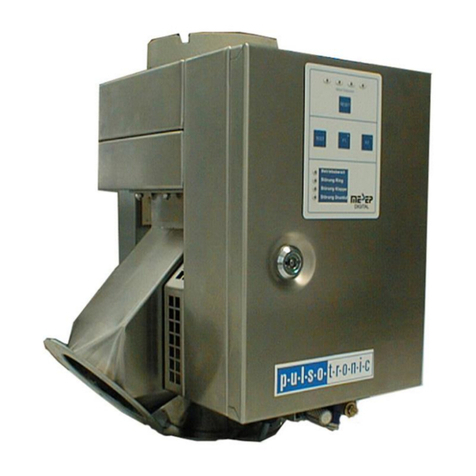
Pulsotronic Mesep Extractor 38...70 Series User manual

1
METAL SEPARATOR
Mesep Extractor
Manual (English)
Mesep Extractor, Version 0701

2
Table of Contents
1. General 3
1.1. Instructionson using themanual 3
2. Area of Utilisation and Qualifications 4
2.1. Intendeduse4
2.2. Improper use4
2.3. Owner/operator’s dutyof care5
3. General SafetyInformation 6
3.1. Explanation concerningutilised safetysymbols6
3.2. Fundamental safetymeasures6
4. Instructions references for the metal separator 8
4.1. Assemblyinstructions8
4.2. Operating instructions8
4.3. Metal separator’s interference protection9
5. Technical Data 10
6. Technical Description11
6.1. Ringdetector andevaluation electronics11
6.2. Cyclone and separatingunit 11
6.3. Sensitivityof thering detector 12
6.4. Product Effects– bothersome product properties 13
7. Transportation 15
7.1. SafetyInformationfor transit and assembly15
8. AssemblyInstructions16
8.1. Assembly16
8.2. Electric connections19
9. Commissioning21
10. Maintenance 23
10.1. General maintenance23
10.2. Cleaning23
10.3. Anti-wear plate (optional) 24
10.4. Regular inspections24
11. Faults and Causes of Errors 26
12. Spare Parts 27
13. Annex28

3
1. General
1.1. Instructions on using the manual
This manual isvalid for the Mesep Extractor 38..70
Manufacturer: Pulsotronic-Anlagentechnik GmbH
Neue Schichtstr. 7
09366 Niederdorf
Tel.: (+49) 372 96/ 9383 500
Fax: (+49) 372 96/ 9383 501
Issue date of documentation:August 2007, Version 0701
This manual contains all theinformationthat is of relevance for the operation.
Before commencingwithwork for the first time usingthe metal detector, this User Manual
should be read and understood byall the persons who are authorized to work on and with
the metal separator. Special stressshould beplaced on the SafetyInformation.
The User Manual is acomponent of the metal separatorand must alwaysbe availablefor
the reference ofthe authorized circle ofpeople. Chapters ofthis manual should never be
removed from the manual at anytime.Replace amissingmanual or missingpages,
especiallythe „SafetyInformation“ chapter immediatelyiflost.
Note:
Pulsotronic does not grant an implied guarantee for the customaryqualityand suitability
for a specificutilisation purpose.
This documentation contains copyrightprotected information. It maynot becopied,
reproduced,translated or collected on data carriers, in whole or inpart, without obtaining
prior permission of Pulsotronic.
This documentation is not subjectto the updatingservices ofPulsotronic.Modifications in
this documentation aswell as all rightsarereserved.

4
2. Area of Utilisation and Qualifications
2.1. Intended use
The Mesep Extractor38..70 is integrated in the vacuum feed line just in frontofthe
material intake. Please ensure that the metal separatoris notpermitted towarm up more
than 50° C. TheMesep Extractor 38..70 eliminates thedetected metal particles atvarious
or varyingflowspeeds, without havingtobe adjusted for thispurpose.
Note:
The Mesep Extractor 38..70 removes metal contaminants out ofpourable, drymaterial
column, which are drawnthroughthe conveyor system and into the bymeans ofvacuum,
via aflap. The Messep Extractor 38..70 was developed to protect plastic injection
moulding machines, extruders or peripherals against metalcontamination ofall kinds.
Asmall quantityofthegood material is alsodischarged duringtheseparating
process,althoughthe reliable removal ofmetal is in the foreground and aslight loss
ofmaterial is technicallyunavoidable.
It is necessaryto observe a fewmarginal and usageconditions in order that the device will
function reliably.This manual will dealwith these points. Thus,readingthis manual is
absolutelymandatoryto ensure atrouble-freeoperation.
The maximum responsesensitivityto metals is subjecttotechnical andphysical limits
(see chapter onTechnical Data). The Mesep Extractor38..70 is not suitable forremoving
metal from materials that fall freelyor inside conveyor lines that arepressurized.
The Mesep Extractor 38..70 can be used to minimizedamagesdue to metal
contamination. Regular inspections of the devices is absolutelymandatoryas components
are involved, which could malfunction due to external influences orwear, in spite ofthe
latest technology.
2.2. Improper use
The Mesep Extractor 38.70 metal separatoris not intended foranyother type ofuse
than those indicated in 2. Area ofUtilisation and Qualifications;anythingelse is
considered animproper use!
Please note that the followingis forbidden:
• Removal or modification ofthe safetydevices
• Usingthe metalseparator for an unapproved use
• Convertingthemetal separatorwithout Pulsotronic’s permission in orderto useitfor
another purpose.Bearinmind that you maybeconsidered themanufacturerofthe
metal separatoraftersuch aconversion, along with all the consequences thatare
involved!

5
2.3. Owner/operator’sdutyof care
The Mesep Extractor38..70 Metal Separator has been designed and constructed
accordingto harmonized standards.Thus, it complies with the latest technologyand
ensures the highest possible degreeofsafety.This safetycan onlybe achieved in
operational practice ifallthe measuresfor this havebeen undertaken.Planningthese
measures and controllingtheir implementation belongsto the owner/operator’s dutyof
care.
Theowner/operator must especiallysafeguardthe followingin particular:
• that the metal separatoris onlyused for the intended purpose,(see 2.1,
“Intended Use”);
• that the metal separatoris onlyoperated when it is in aperfectlyfunctioning
condition and that thesafetyequipmentin particular is examined at regular
intervals to ensure it is functioning properly
• that theOperating Manual is available at all timesand is ingood legible condition
• that onlyadequatelyqualified andauthorized staff mayoperate, service and repair
the metal separator
• that thepersonnelmust be trained on all matters ofoccupational safetyand
environmental protectionbefore starting to workwith it for thefirst time and must
be familiar with the Operating Manual and especiallythe Safetyreferences
contained therein
• that none of the safetyand warninginformation that hasbeen attached tothe
machine is removed andthat it remains legible

6
3. General SafetyInformation
3.1. Explanation concerning utilised safetysymbols
The followingsafetysymbols are used in the OperatingManual concerned here.These
symbols are mainlyintended to drawthe reader’s attention to the textappearingbeside
the safetyreference.
Danger!
This symbol indicatesthat there are dangers for lifeand limb.
Danger!
This symbol indicatesthat there are dangers for lifeand limbdue
to electrical voltage.
3.2. Fundamental safetymeasures
• Do not reachinto the openings onthe metal separator.
Mechanical forcesarecreated after switching on the
pneumaticallyoperatedpoints, which could cause injuries.
• Always disconnect thedevice from thecompressed air and
voltage supplybefore performinganymaintenance work. Please
ensure that no onecanre-connect thecompressed air or voltage
supplybefore the workiscompleted.
• Never put the metalseparator intooperation without the safetyequipment requiredon
the factoryside. These include the safetygrates over the movingpartsin particular.
• Immediatelydiscontinue the operation if the safetyequipment is not functioning
properlyor isdamaged.
• If technical malfunctions occur duringoperation due towear or fatigue, rectifythese
immediately.
• Set out asufficient number of regular maintenance intervals.
Alwaysobservethe safetyinformation which islocated on the unit itself. It can help to
avoid dangers. Do not remove this information under anycircumstances.
Do not put themetal separator intooperation if you:
• have not been briefedcompletelybythe owner/operator, or
• have not readthisOperating Manual in full, or

7
• have not completelyunderstoodthisOperating Manual.
Operating errors canresult in serious personal or propertydamages.
Danger!
Avoid touching the electronic circuit board.
Disconnect the unit from the supplyvoltage and the compressed air supply
before connecting the electronics to other peripherals. Youwill avoid
unintended electrical short circuits as aresult of this. It is necessaryto
ensure that static charges dissipate before anypossible work commences.

8
4. Instructions references for the metal separator
Trouble-free and safeoperation ofthe Mesep Extractor 38..70 Metal Separator is only
possible, ifthe followingpoints areobserved.
4.1. Assemblyinstructions
• Fastening must be performed in such awaythat none of thescrews or other fastening
materials can becomeloose unintentionally.
• Thedevice maynot be dismantled for assembly. Theassemblymust be carried out as
a complete unit.
• No weldingcurrent maybe allowed to flowthrough thehousingonthemetal separator
under anycircumstances! This would permanentlydestroythemetal separator!
IMPORTANTINFORMATION
The devices are not 100% airtight due to production-related reasons.Therefore, avery
slight loss ofair canbeexpected (approx.17mbar at 16m/sec. air velocity). Thus, the
suction-type conveyor system should havesufficient capacityreserves tocompensate for
this loss, so that the conveyingofmaterial is not affected and sufficientmaterial can be
conveyed to the machines.
Thelosingofcompressed air cannot beheard acoustically(no hissing noises). The
escapingair involved is minimal. All the devices arechecked to ensure theyare
sufficientlyleakproof before leaving the factory.An impairmentin the system has occurred
in some cases ifseveral devices were assembledsimultaneously.Thus, it is necessaryto
clarifythisprior to the installation ofmore thanfivedevices at one time,toprevent any
difficulties. Connection Instructions
• Ensure the mains voltage is theproper one.
• Installation andconnections mayonlybe performed bytrained staff.
• Observe the installation requirements for erecting and operating electrical plant (VDE
0100).
• Never carryout anywork when the metal separator is switched on!
• Carryout all protective measures for persons andmachineryin accordancewith the
circumstancesand regulations.
• Takethecapacitiesof the output contacts into consideration.
• Themetal separator must bewell grounded (avoid star-shapedearthcircuits, shortest
linkto main earth).
4.2. Operating instructions
The metal separator should remain switched on at all times.Thatway,the electronic
circuits have the longest service life.

9
4.3. Metal separator’sinterferenceprotection
Themetal separator’s power input is protected against parasitic inductionbythe factory.
Even higher operationalsafetyand additional protection against functional faults is
achieved through the followingmeasures:
• Use ofline filters, ifthemains voltageis affected byswitchingon other large
consumers (compensation systems, weldingdevices, HF furnaces,electromagnetic
valves, etc.)
Protectivecircuitryforinductiveloads (solenoids, gates, electromagnets) as aresult ofRC
elements.Highvoltagepeakscan result fromshuttingoff inductiveloads. These high
voltage impulsesareshort-circuitedbythe RCelements.

10
5. Technical Data
Item designation Mesep Extractor 38,45,50 (with 50 mm ring)
Mesep Extractor 55,60,65, 70(with 70 mm ring)
Operating voltage 230 V / 50 Hz or 115V /60Hz
Power consumption < 40Watt
Admissible operating temperature 0°C - 50 °C
Admissible product temperature Max. 60°C (with compressed air cooling max. 100° C)
Weight About 32 kg
Adjustable sensitivity(Max.) Mesep Extractor 38.0.50 0.6 Fe in centre ofring FE-
St37
Mesep Extractor 55..70 1.0 Fein centre ofring
FE-St37
Material throughput Type-dependent 600..3300 l/h, depending on
complete conveyorsystemand conveyed material
Sensitivitysetting Using potentiometer
Operating pressure 4-6 bar filtered, free ofwater and oil
Partstouching media Paper-based laminateandstainless steel
Relay contacts Metal detection (floating changeover contact 250V/5A)
Paintwork - housing RAL 5005
Measurements 450 mm* 450 mm* 300 mm

11
6. Technical Description
This chapter provides information on the configuration and wayin which your metal
separator operates.
TheMesep Extractor 38..70 Metal Separator consists of threemain functional units:
o Ringdetector / Chapter 6.1.
o Evaluation electronics / Chapter 6.1.
o Cyclone and separating unit / Chapter 6.2
6.1. Ring detector and evaluation electronics
The toroid’smetal detector operates usingan analogevaluation principal,which is briefly
explained below.
Ahighfrequencyelectromagnetic alternatingfield is produced in aringsensor bymeans
ofan oscillator.If ametal piece or electricallyconductible materials fall throughthe ring
sensor,eddycurrents are produced inside it. These removethe energyfromthe
electromagnetic field.This energyloss causesdampening oftheoscillator,which in turn
reduces the signal amplitude. The sizeofthe dampeningis ameasure for the sizeofthe
metal piece and hasadirect relationship with the magnetic and electric properties ofthe
metalparticle:
Large metal particles draw more energyfrom the field than small metal particles.
Magnetic metals (e.g.steel) drawmore energyfrom the field than non-magnetic metals
(e.g. aluminium).
This measuringprinciple is suitable forall types ofmetal and makes it possible to detect
metalparticiples within product or in non-metallic packaging.
Theexamined productsare not affected or changed in anywaybythis kind of measuring.
The threshold value, thesizefrom which metal isdetected, is setusingapotentiometer.
Once this value is exceeded, the device tripsanelectrical impulse. Aflap is addressed
with this impulse in metal separators bymeans of the evaluation electronics and the metal
particle isthendischarged into the flowof rejects.
6.2. Cyclone and separating unit
The conveyor system sucks the material through the metal separator. There, it passes the
metal sensorfirst, and then flowsthroughacyclone and subsequentlyleaves the device
via a separatingfilter.
Ifmetal is detected,this separating filteropens, in order todiscardthe metal foreign
matter. Aslight quantityofthe good material is also discharged in the process.
Compressed air is blowninto the cyclone throughthe ringat the same time; this removes

12
anysuch metal pieces that might havecontinuedto remain behind the ring. This blowout
effect also cleans the entire cyclone, the separatingfilter and the ringdetector at the same
time.
The separating filter independentlyfoldsbackinto theoriginal position and the conveying
continues.
The conveyed material enters the upperpart ofthe cyclone tangentially.The flowspeed
forcesthematerial into aspiral motion, which is directedin a downward direction.
As aresult ofthe combined effectwith the blown in compressed air, thematerial spiral
breaksdowninsidethe cyclone and the drops out (approxone handful ofmaterial). And
preciselythis causestheindependence of various flowspeeds within the system.
Automatic adapting tothe material speed.
The electronic metal detection within the sensor occurs with practically notime delay.On
the otherhand,thereis adelayin the separatingmechanism, which requiresacertain
time (even ifit brief) toflip from position 1toposition 2.
The result is thatmetalparticles that aretravellingquicklypenetratequite farinto the
cyclone after theyare detected,before the separatingfilter has responded fully.Aslow
flowcausestheexact opposite tooccur.
As everythingis separated out ofthe cyclone, it makes no difference whether the material
is right at the top ofthecyclone or alreadyinside the separatingfilter or somewhere in
between; it will be separated regardless.
6.3. Sensitivityof the ring detector
In the event that the ringdetector reacts to theproduct effects (see Chapter Product
Effects 6.4), it is necessaryto reduce thesensitivity.
Thesensitivityis set onthe ringdetector using a potentiometer.
The dooron the housingis opened forthis purpose. The ring detectoris located at the top
left. Apotentiometer, which is secured byaretainingscrewto prevent unintentional
repositioning, islocated there. Loosen the little slottedretainingscrew.
You can nowchange thesensitivityas follows:
Turning to the left
up tothepotentiometer limit stopcausesthe sensitivityto be reduced.
Turning to the right
up tothepotentiometer limit stopcausesthe sensitivityto be increased.
Once you reach thelimit stop, please donot tryto use force to turn the
potentiometeranyfurther. The potentiometer will break off and will be permanently
damaged, and the completedevice will malfunction.

13
The potentiometer has avisible scale between1and 10. The setvalue should be
recorded and controlled at regular intervals. That is the onlywayto determine whether or
not someone has alteredthesetting. At delivery, the potentiometer is set to Level 8.
NOTE: For detection accuracy,it is irrelevant, whether metal parts are covered by
material or not.
Non-magnetic metals affect the magnet field of thering spool less intensely than magnetic
ones. Thus, you should expect touse areducedresponsiveness for thesemetals.
SensitivityIronStainless steel
Mesep Extractor 38, 45, 50 (with 50 mmring) 0.6 mm 2.0 mm
Mesep Extractor 55, 60, 65, 70 (with 70 mmring) 1.0 mm 2.5 mm
6.4. Product Effects –bothersome product properties
This chapter explains:
• what is understoodbythe term ’product effect’;
• whythe metal separator reacts to aproduct effect.
This knowledgewill help you to use the best possible settingfor the metal separator in
order toavoid anyspurious releases.
What isunderstoodbythe term ‘product effect’?
The metal separator reacts to magnetism andelectric conductivity.Because ofthis,
electricallyconductivesubstances,as is the case with metal, will affectthe measuring
field. This results in atest signal for the electronics, similar to what occurs when metal is
reported. This is referredto as anegativeinfluence on the magnetic field due to product
effects.
The result ofthe product effect is ametal report by the metal separator,althoughin reality,
the product is metal-free.
Please keepin mind, for example, howsalt changes theconductivityofwater.
The electricresistance ofdistilled water is infinitelyhigh, provided the water is pure
distilled water. Distilled water does not containany salts or minerals.
Dissolved salt changesthe electric resistanceto suchan extent thatthesolution is
electricallyconductive. Similarly,some plasticshaveconductiveproperties dueto the
admixingof materials.
Rawmaterials aremore or lesselectricallyconductive. Componentssuch as:
• Salt
• Sugar
• Minerals
• Moisture
• Carbons (plastic granulate died black)
cause thematerials to be more or less conductive. The magnetic fieldis continuous
affected asaresult. Althoughthere are no metalparticles in the examined material, the
metalseparator maystill report metal. The results are unnecessaryrejects.
The producteffect takeson acharacteristic value for everymaterial. The achievable
sensitivity in practice is dependent on howwell apotentiallyexistingproduct effectcan be
compensated bythemetal separator.
The Mesep Extractor 38..70 ofthis model has noproduct effectfade-out(compensation)
possibilities. Frequently,however,reducingthe sensitivityis all that is required to avoid

14
this bothersome effect. The achievable sensitivityhowever in metal detection systems with
integratedproduct effect compensation is considerablyhigher.
(Please ask our head office for product group M-Pulse or Digital+ Extractor).
Suppressing product effectsin the Mesep Extractor 38..70:
Aproduct effectcan onlybe suppressed to acertain extent in the Mesep Extractor 38..70
byreducing theresponsiveness (see Chapter 6.3.).
Note: The intensityof the product effectis proportionalto the material throughput.
Asaresult of this,reducing thematerial throughput with critical materials canalso
bring about areduction inthebothersome effects.

15
7. Transportation
7.1. SafetyInformation for transit andassembly
Danger!To avoid machine damages or life-threatening injuries
during transit and the installation of the metal separator, please
observe the following points absolutely:
• Transit and assemblyworkmayonlybe carried out byqualified persons under
observation of thesafetyinstructions.
• Takethefollowingweights into considerationwhen selectingsuitable load-bearing
equipment:
àMetal separator, depending onsizeand model, to32 kgapprox.
• Protruding, sharp edges can result in injuries dueto cuts.
• Suspended loads canfall down resulting in mortal danger; never walkor stand
underneathsuspendedloads!
• Partsthat arelooselylying on top of eachother can slip and fall down.
• Also read the chapter entitled "General SafetyInformation".

16
8. AssemblyInstructions
8.1. Assembly
The sturdyhousingon the Mesep Extractor 38..70 metal separatorhasfourfastening
brackets, which makewall assemblysimple and fast. It is also conceivable that the unit
could be usedon amobile rack.
The setup location should be chosen in such awaythat there is sufficient space for
performingservice workand so that it ispossible to opentheupper inspection flap andthe
housingdoor.
The metal separatormust be assemblyhorizontallyto ensure it functionsin atrouble-free
manner. Theother two axes must be arrangedvertically.
Theunit will not operate in a horizontal position.
In principle, the Mesep Extractor 38..70 and theconveyor system mustbe switched off
when the followingsystem is connected.
1. Opening of the existing suction-type conveyor line
2. The material feed (incoming line)is connected to the left inlet socket onthe
Mesep Extractor 38..70bymeans ofaplastic hose or metal tube. It is
necessarytoensurethis connection is leakproof, to avoid anyloss ofpressure.

17
3. The material feed (incoming line)is connected to the left inlet socket onthe
Mesep Extractor 38..70bymeans ofaplastic hose or metal tube. It is
necessarytoensurethis connection is leakproof, to avoid anyloss ofpressure.
Inlet socket
Dischargesocket

18
4. The reject material chuteon theMesep Extractor 38..70 situatedon the bottom
ofthe housingis connected to acollection container or asimilar system by
means of ahoseor tube.
5. Mount the metal separator in such awaythat it will suffer as little as possible
shaking when in operation. Slight vibrations donot affect the separator. A metal
alarm canbetriggered thoughthrough ahardknock.

19
8.2. Electricconnections
Explanationof individual connections:
11/12: Optional compressed air monitoring (not standardly configured)
An optional sensorcanbe connectedhere,whichmonitors thelevel of the
compressed air.
16/17: Test key/ Metal simulation
Tests can also be triggered via an external floatingcontact, which is
connected inparallel.
18/19: Output: 24 VDC/100mA
Permanent signal, for asignal lampsuitable asanequipment-on indicator
24/25/26: Onlyoptionallyequipped with changeover contact 250V/5A
Breakcontact on25 and26
Make contact on24 and25
1 + Red
2 R Black
3 A White
4 - Blue
5 Solenoid valve
6 Flap
7 Optional: solenoidvalve
8 Voltage and compressedair monitoring
Ring-Pulsor
16 17 18 19
Poti. A Poti. B
27 28 L1N
S1
F1
24 2526
11 12

20
This isused for monitoring thevoltageor thecompressedair
Changeover(N.O./N.C.) contacts 250V/5A
27/28: Closer contact 250V +/- 5A
Shut when metal is ejected
L1/N: Mains feed (230 VAC / 50 Hzor 115VAC / 60 Hz)
A: For settingtheflap holding timein “Eject metal” position of
4 sec. – Left limit stop
sec. – Right limit stop
Exits 27/28 are also connected forthe time the flap is open in “Eject metal“
position.
B: Settingthe blow-off time ofthe cyclone with compressed air
(preset at thefactory)
F1: Mains fuse: 230 VAC – 0.25A time-lag fuse
115 VAC – 0.5 time-lag fuse
S1 Mains changeover switch for selling operating voltage
Table of contents
Other Pulsotronic Water Filtration System manuals
Popular Water Filtration System manuals by other brands

GE
GE Whatman Mini-UniPrep G2 Product information sheet

Culligan
Culligan US-600A Installation and operating instructions

Linn
Linn Aqua-Handy operating instructions

Premier
Premier RO-TFM-4SV/W50 Installation, operation and maintenance manual

elysator
elysator PUROTAP compenso 2 operating instructions

WaterLogic
WaterLogic WL380 Troubleshooting

amiad
amiad SAF-3000 Installation, operation and maintenance instructions

H2WaterForLife
H2WaterForLife H2 USB Sport PRO II quick start guide

Kongskilde
Kongskilde RVS 5000 Operator's manual

Hayward
Hayward Super Star Clear C2000 owner's guide

Scheiber
Scheiber 38.14701.00 quick start guide

3M Purification
3M Purification AP101 instructions