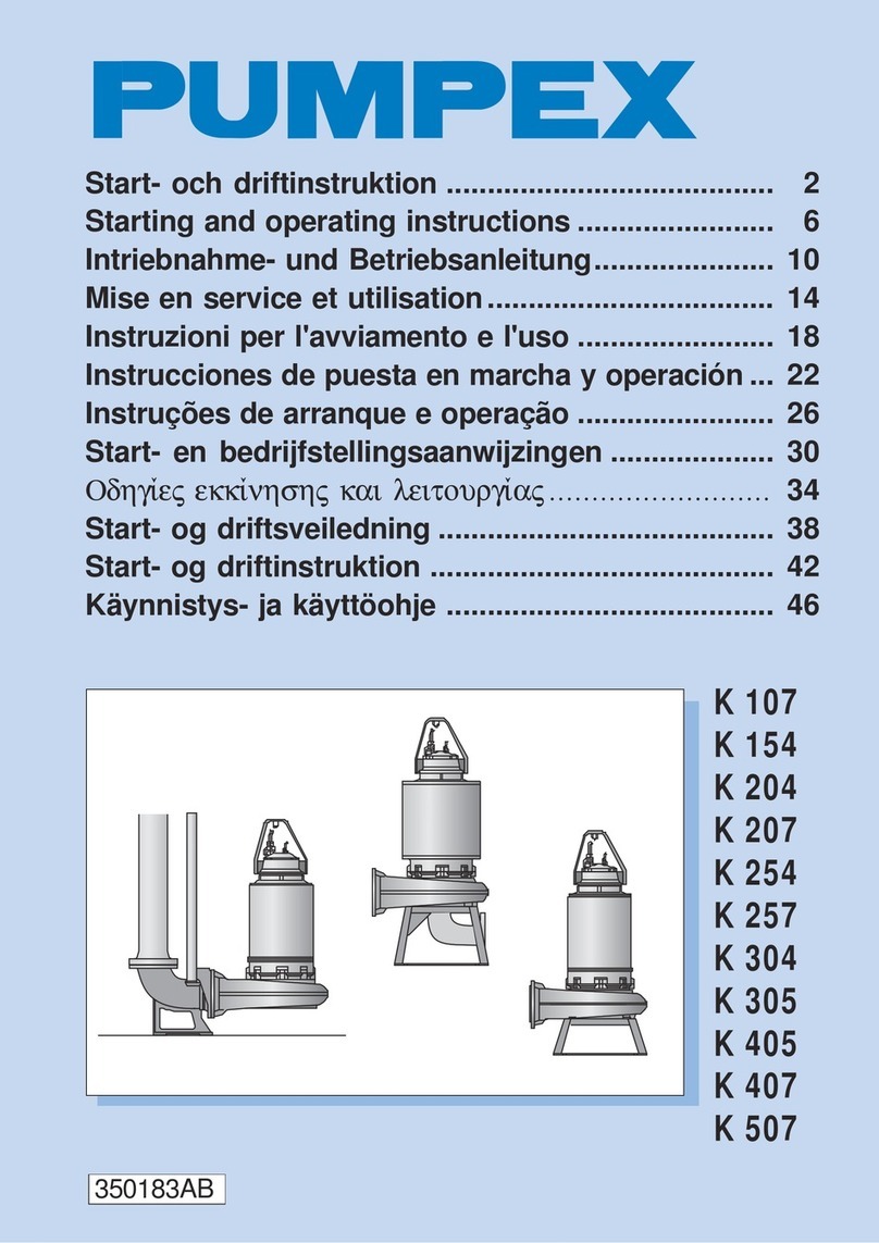
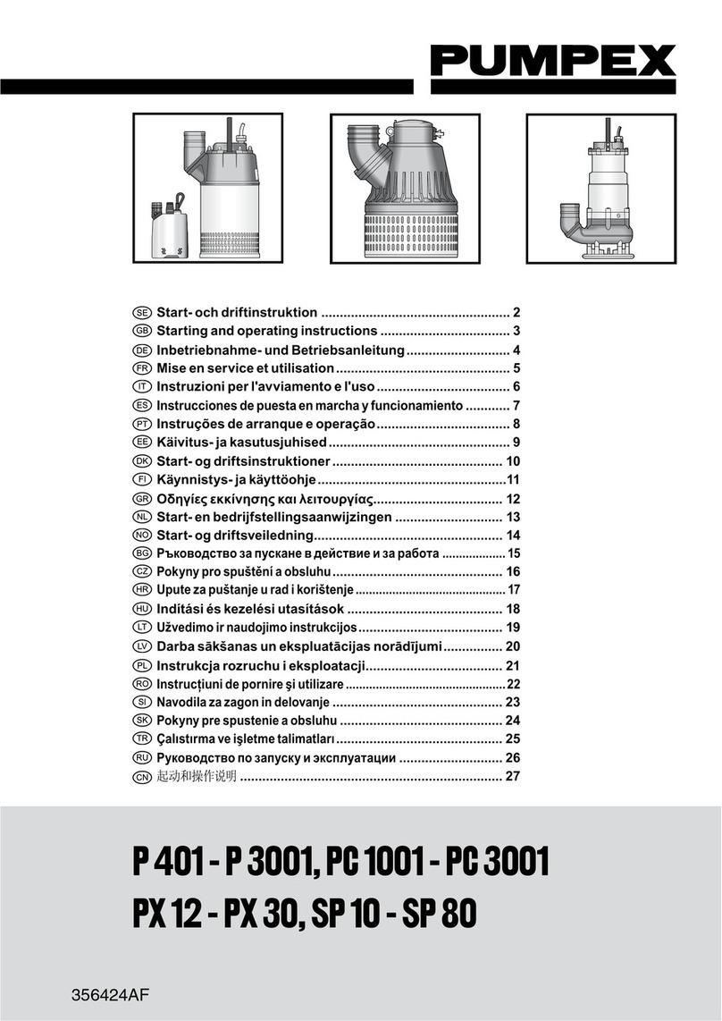
Pumpex K 152 Operating instructions

K 152, 202, 203, 252, 302
SERVICE INSTRUCTION
1 (15)
K152/202/203/252/302.58.0101.Eng/Digital

2 (15)
SERVICE INSTRUCTION
K 152, 202, 203, 252, 302
K152/202/203/252/302.58.0101.Eng/Digital
This Service Instruction applies to the following Electric
Submersible Wastewater Pumps: K 152, K 202, K 203. K 252,
K 302.
Type F Wet Pit Installation
Installedonaguiderailsystemwithaquick-releasebaseelbow,
the base elbow is bolted to the floor of the sump. The volute is
equipped with an adapter to be connected to the discharge
elbow.
Two twin guide rails are mounted to the discharge elbow to
steer the pump into right position when hoisted up and down.
The motor has an internal cooling system. The motors are
equipped with a maintenance-free internal, closed loop cooling
system which dissipates the heat to the liquid that is being
pumped.
Type T, Dry Pit Installation
Installed in a normally dry well, but still fully submersible. The
pump is supported by an adjustable fabricated steel stand,
mounted at the factory. The height of the stand is sufficient for
the standard suction elbow to be used on a flat floor.
The pump volute is drilled or threaded on the connection-flange
and equipped with studs on the suction flange. The motors are
equipped with a maintenance-free internal, closed loop cooling
system which dissipates the heat to the liquid that is being
pumped.
Type P, Wet Pit Portable or fixed installation
A version of pump which is suitable for temporary or permanent
installations.Thepumpisequippedwith a fabricated steel stand
and either a threaded (BSP, NPT) or plain hose connection.
The motors are equipped with a maintenance-free internal,
closedloopcoolingsystemwhichdissipatestheheattotheliquid
that is being pumped.
Installedbelow liquid level with dis-
chargeelbow
Installedbelowliquid level, either
stationary or for portable
Dry installation with cooled motor.
Suctionbend provided with cleaning
cover.

3 (15)
K152/202/203/252/302.58.0101.Eng/Digital
SERVICE INSTRUCTION
K 152, 202, 203, 252, 302
Pump design
The design of the pump features high reliability and easy main-
tenance.Themajorpartsofthepumparefewinnumbersanddo
not require special tools during disassembly and assembly.
The electric motor unit consist of Stator Unit (Stator and Stator
Housing), Rotor Unit (Rotor, Shaft and Bearings) Impeller, Oil
Housing,MechanicalShaftSealUnitandJunctionBox(Junction
Box Cover, Terminal Board and Cable Entries).
The motors are always equipped with a maintenance-free
internal, closed loop cooling system which dissipates the heat to
the liquid that is being pumped.
An exchange system is used for the Stator Unit and Mechanical
Shaft Seal Unit.
Box 5207 S - 12116 JOHANNESHOV SWEDEN
5
67
8
9
1
2
3
4
K80
No 99999999 P.2 2.0 kW3Ph50 Hz
U400 V Yn1385 rpm Class FIP68
I5,4A 98kg
20 m
1 Type of pump
2 Serial number
3 Working voltage
4 Rated current
5 Rated output
6 Engine speed
7 Frequency
8 Winding class
9 Weight
A Type of pump
B Serial number
C Working voltage
D Rated current
E Rated output
F Cos ϕ
G Frequency
H Head
I Speed
Technical data
The technical data are stamped on the data plate, which is
located under the pump handle.

4 (15)
SERVICE INSTRUCTION
K 152, 202, 203, 252, 302
K152/202/203/252/302.58.0101.Eng/Digital
Disassembly
Remove the pump from the pit and rinse it with water.
Warning!
Always check that the pump is disconnected from the electric
power supply and cannot be energized, prior to any work being
carried out.
The motor unit is assembled to the volute by two (2) latch bolts.
Loosen the latch bolts with a wrench (supplied with the pump)
and turn the latches free from the flange of the motor unit. The
motor unit can now be separated from the volute.

5 (15)
K152/202/203/252/302.58.0101.Eng/Digital
SERVICE INSTRUCTION
K 152, 202, 203, 252, 302
Exchangeofoil
Exchange of oil should be carried out if the oil is discoloured by
water or when a complete overhaul is done.
Place the motor unit on the floor or a low work bench. Loosen
theoil stick carefully to relieve over-pressurein the oil chamber.
Tightenoil stick again and loosen theoil plur, on the oil housing.
Regulate the oil flow by loosening the oil stick to allow air into
the oil chamber. Tilt the motor unit to drain all the oil from the oil
housing.
Replace the 0-rings for oil plug and oil stick and tighten the oil
plug. Fill new oil through the hole for the oil stick.
Oil type: Enerpar M002, or similar.
Oil quantity:
11-15 kW motor - 14.5 litres
23-40 kW motor - 18.5 litres
Don´t forget to tighten oil stick.
Removal of Impeller
The impeller is fitted on a cylindrical shaft end. To simplify the
loosening of the impeller bolt, place a piece of wood (pipe or
similar) inside the impeller to keep it from rotating. Loosen the
impeller bolt with a socket wrench (socket 22 mm).
The impeller has a relatively light fit on the shaft and is using a
flat key. The impeller can be removed by using two (2) pry bars
orlarge screwdrivers.

6 (15)
SERVICE INSTRUCTION
K 152, 202, 203, 252, 302
K152/202/203/252/302.58.0101.Eng/Digital
RemovaI of Mechanical ShaftSealUnit
Remove the three (3) screws holding the seal unit to the oil
housing bottom. The seal unit flange is provided with two (2)
threadedholes.Cleantheholeswithasmallscrewdriver(ortap
M 6).
Remove seal unit by using two M 6 screws, approximately 40 mm
in length, fitted into the threaded holes. By turning the screws
evenly the seal unit will back off from the oil housing bottom.
A defective seal unit should always be replaced. The defective
seal unit should be sent to the nearest service point in ex-
change for a rebuilt unit.
Removal of Stator Unit
Place the motor unit in an upright position. Remove the screws
holdingthestatorhousingandoilhousingtogether.Removethe
two (2) plastic caps and screw two screws M 12 into the threa-
dedholes.
Tighten the screws to separate stator housing and oil housing.
The stator unit can now be lifted away from the oil housing and
shaft-/rotor unit. If stator unit doesn’t separate, tap oil housing
gently with a soft hammer.

7 (15)
K152/202/203/252/302.58.0101.Eng/Digital
SERVICE INSTRUCTION
K 152, 202, 203, 252, 302
Removal of Shaft/Rotor Unit and Bearings
The shaft/rotor unit and oil housing is held together by six (6)
screws in a bearing cover above the lower ball bearings. Remove
the screws and press out the shaft/rotor unit.
Bearings which have been in contact with water or otherwise
damagedshall be replaced.
Place the shaft/rotor unit in a wise with soft jaws. Remove the
circlip and bearing washer from the shaft.
Screw the impeller bolt onto the shaft in order not to damage the
threadswhenusing a bearing puller. Mount the puller over the ball
bearings and pull off the bearings. Turn the rotor over in the wise
and pull off the upper ball bearing with a puller.

8 (15)
SERVICE INSTRUCTION
K 152, 202, 203, 252, 302
K152/202/203/252/302.58.0101.Eng/Digital
Exchange of Stator Unit
If the motor overload protector has tripped repeated times, the
stator should be checked. Remove the junction box cover.
Remove the motor cable leads from the terminal board.
Record the colours of the cable leads and corresponding
terminal board letters (or numbers).
Check the stator insulation by using a 500 V megger. The
megger reading should exceed I megohm between the winding
phases as well as between the windings and ground (stator
housing). If the insulation resistance is below 1 megohm the
stator unit should be dried in an oven, the temperature pre-
ferably not to exceed 90°C.
Check the circuit of the three (3) built-in thermal contacts for
continuity, using an ohm meter or bridge. If the circuit is open
the defective contact should be identified by checking each
individual thermal contact. The faulty thermal contact can be
bypassed in accordance with the wiring diagram on page 9.
If stator insulation reading after drying is still low, the stator unit
should be replaced. Remove terminal boards (and terminal
board plate). The defective stator unit (stator and stator housing)
should be sent to the nearest service point in exchange for a
rebuilt unit.

9 (15)
K152/202/203/252/302.58.0101.Eng/Digital
SERVICE INSTRUCTION
K 152, 202, 203, 252, 302
Disassembly of Cable Entry
If water has penetrated through the cable entry into the junction
box, the cable entry bushings should be replaced. Remove strain
relief clamp on cable entry prior to unscrewing cable entry body.
Pull out cable, rubber bushing and washers.
Assembly
Prior to assembly, clean all parts carefully especially 0-ring
groves and mating surfaces. Grease or oil 0-rings to eliminate
damage during assembly.Putsomegrease or oil on screwthreads
tosimplifydisassembly during future overhaul.
Assembly of Cable Entry
Measure inner diameter of cable entry rubber bushing to see that
it corresponds to cable diameter. Place rubber bushing and
washers (one (1) on each side of the bushing) on the cable.
Pull cable through the junction box cover, far enough to let the
rubber bushing seat on a non-deformed portion of the cable.
Tighten the cable entry body. Fit the strain relief clamp in such a
way that it prevents the cable entry from loosening.

10 (15)
SERVICE INSTRUCTION
K 152, 202, 203, 252, 302
K152/202/203/252/302.58.0101.Eng/Digital
Assembly of Bearings
Check that the shaft is straight and key slot not damaged. Clean
the shaft from burrs and foreign materials. Slide the bearing
cover on to the shaft in such a way that the cover hub is facing
the rotor.
Pack lower bearings with grease (type SKF Alfalub LGHT 3/1 or
similar) and slide the bearings on to the shaft with the wider
sides of the inner rings facing each other. See sketch.
Placeupper bearing on the shaft and press allthree (3) bearings
into positions, i.e. against the shaft shoulders.
Mount bearing washer and circlip on the shaft below lower
bearing.
If a press is not availabIe, heat bearings to 100-120 °C in an oil
bath prior to assembly.
Note: Do not overfill bearings and bearing covers with grease.
Bearing manufacturers recommend to fill covers and bearings
2/3full.

11 (15)
K152/202/203/252/302.58.0101.Eng/Digital
SERVICE INSTRUCTION
K 152, 202, 203, 252, 302
Assembly of Shaft/Rotor unit and Oil Housing
The shaft/rotor unit with bearings, is now complete and can be
assembled to the oil housing. Press the lower bearing into the
oil housing by hand. Lock the shaft/rotor unit into position by
tightening the six (6) screws for the bearing cover. Turn shaft/
rotor unit by hand to check that it turns freely.
Checkthat the clearance between bearing cover and oilhousing
is about 1 mm.
Assembly of Mechanical Shaft Seal Unit
Place oil housing and shaft/rotor unit on its side for assembly of
the mechanical shaft seal unit. Add some oil to the shaft and
apply grease on the 0-rings of the shaft seal unit (there are two
(2) 0-rings fitted on the seal housing and one (1) inside the shaft
sleeve).
Slide the seal unit on the shaft and press gently into position. Do
not use hammer. Tighten the three (3) screws firmly.
Fill oil as described in
"Exchange of oil".
NOTE!
Never run the motor without having the impeller mounted, if
theseal ismounted. ThiscancausedamagetoO-ringsinseal.
Assembly of Stator Unit
Theupper bearing seat of the statorunit includes an 0- ring. Add
some oil or grease on the 0-ring prior to assembling the stator
unit and shaft/rotor unit/oil housing.

12 (15)
SERVICE INSTRUCTION
K 152, 202, 203, 252, 302
K152/202/203/252/302.58.0101.Eng/Digital
Fit the terminal board plate (and terminal
boards) and tighten the three (3) screws.
Clean the 0-ring groove of the junction box cover and oil the 0-
ring. Connect the motor cable leads to the terminal boards.
Pressdownthe junction box cover and tighten the screws firmly.
Becareful not to pinch wires, and always usespring washers for
the screws.
Place the shaft/rotor unit/oil housing assembly in an upright
position and remove the old gasket. Clean the mating surfaces
between oil housing and stator housing with a knife or scraper.
Cover up the oil channels to avoid foreign objects from falling
down into the oil chamber.
Applyglue,e.g.Permatex,on bothsidesofthegasketandmountit
on the oil housing. Check that the oil channels are open.
Old Marking New Marking Old Marking New Marking
1Green Black 1 4 Red Red 4
2Black Black 2 5 Yellow Red 5
3 Blue Black 3 6 Brown Red 6
Connect the stator leads to the terminal
boards in accordance with the wiring diagram

13 (15)
K152/202/203/252/302.58.0101.Eng/Digital
SERVICE INSTRUCTION
K 152, 202, 203, 252, 302
Liftthe stator unit in a hoist and placeit over the shaft/rotor unit/oil
housingassembly.
Lower the stator unit into position. Be careful not to damage
windings and check that the oil circulation channels are facing
each others.
Tighten the eight (8) screws holding the stator unit to the shaft/
rotor unit/oil housing assembly and mount plastic caps in the two
(2) threaded holes.
Assembly of Impeller
Place the flat key in the shaft key slot. The impeller can now be
pressed on the shaft by hand. Lock the impeller with a piece of
wood (pipe or similar).
Mount impeller bolt with washer and tighten firmly. Recommended
torque is 9 kpm (88 Nm),

14 (15)
SERVICE INSTRUCTION
K 152, 202, 203, 252, 302
K152/202/203/252/302.58.0101.Eng/Digital
Assembly of Volute
Turn the volute latches away from the centre of the volute and
assemble the volute to the motor unit. The volute flange should
meet firmly with the mating surface of the motor unit. Turn
latches into locking position and tighten the bolts evenly.
Recommended torque is 28-30 kpm (275-295
Note!
For Dry Pit Installation an 0-ring is used between volute and oil
housing.
Adjustment of Volute Wear Ring
Lay the pump on its side and check the clearance between
impeller and volute. The clearance shall be max. 0,7 mm.
Should the clearance be larger, loosen the screws holding the
adjustable volute wear ring and tap the ring gently with a soft
hammer until clearance is correct. Tighten the screws.
Note!
Older pump versions do not have adjustable wear rings. The
clearance is adjusted by using shims between impeller hub and
shaftshoulder.
Note! This applies only if using channel impeller. If using
vortex impeller do not adjust the wear ring!

15 (15)
K152/202/203/252/302.58.0101.Eng/Digital
SERVICE INSTRUCTION
K 152, 202, 203, 252, 302
Testing
Connect motor cable to power supply and start the pump. The
starting arrow shown on the junction box cover indicates direc-
tion of rotation,
Note!
Each time the pump is removed, check lifting handle and that
correspondingscrews are firmly tightened.

This manual suits for next models
4
Table of contents
Other Pumpex Water Pump manuals

Pumpex
Pumpex KV 30 How to use

Pumpex
Pumpex K 80 How to use

Pumpex
Pumpex KG 30 User manual

Pumpex
Pumpex P 401 How to use

Pumpex
Pumpex K 82 Original operating manual

Pumpex
Pumpex K 107 How to use

Pumpex
Pumpex P 601 Original operating manual
Pumpex
Pumpex K 101 Original operating manual
Pumpex
Pumpex K 60 How to use
Popular Water Pump manuals by other brands

Graco
Graco Series A Instructions-parts list

Grundfos
Grundfos CRK Series Installation and operating instructions

Grundfos
Grundfos CRK 2 Installation and operating instructions

SMC Networks
SMC Networks PB1313A Operation manual

YATO
YATO YT-85330 Original instructions

SFA
SFA SANIFOS 110 Installation and operating manual