manuals.online logo
Brands
  1. Home
  2. •
  3. Brands
  4. •
  5. Pumpex
  6. •
  7. Water Pump
  8. •
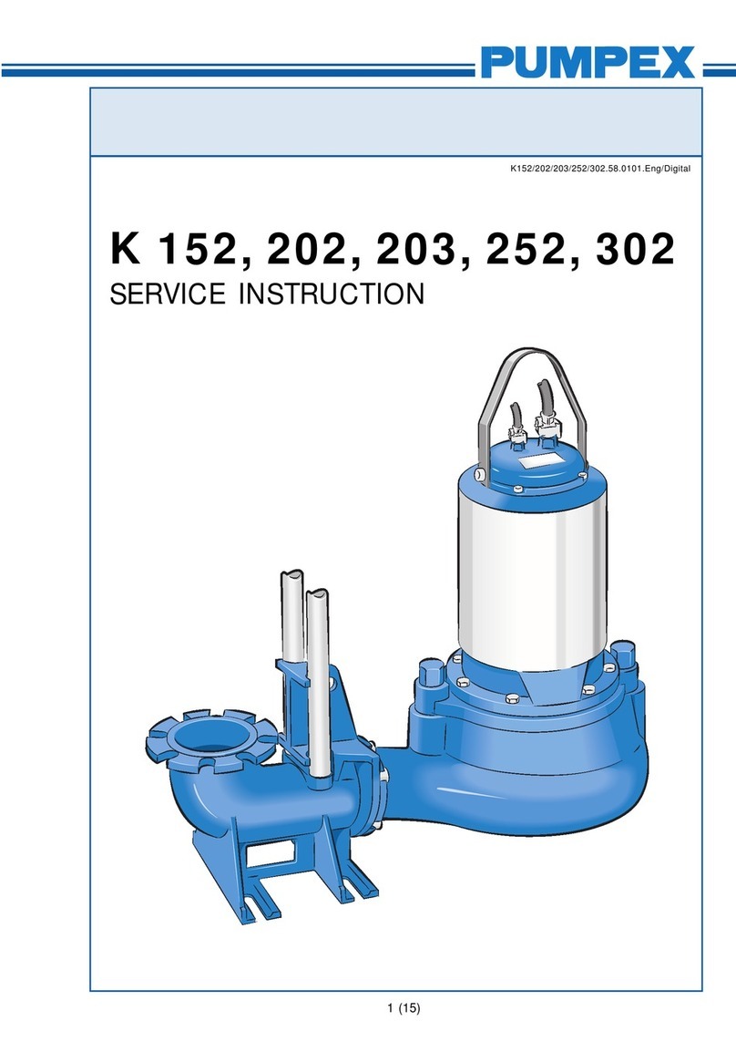
  9. Pumpex K 82 Original operating manual

Pumpex K 82 Original operating manual

K 82, 85, 101, 102,
104, 151, 155
SERVICE INSTRUCTION
K82/85/101/102/104/151/155.58.0211.Eng/Digital
1 (13)
2 (13)
SERVICEINSTRUCTION
K 82, 85, 101, 102, 104, 151, 155
K82/85/101/102/104/151/155.58.0211.Eng/Digital
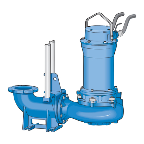
This Service Instruction applies to the following Electric Sub-
mersible Waste Water Pumps: K 82, K 85 K 101, K 102, K 104,
K 151, K 155.
Pump designations:
KP-F i s a stationary Waste Water Pump equipped with a
channel type impeller. The pump is designed to operate com-
pletely or partially submerged in the liquid. It connects auto-
maticallytoaDischargeConnectionfixedtothesumpfloor.The
pump can easily be hoisted up along guide bars for inspection
andservice.
KL-V is a stationary Waste Water Pump equipped with a
vorteximpeller. Operation and installation arrangement is equi-
valent to KP-V.
KP-T is a stationary Waste Water Pump equipped with a
channel type impeller. The pump is designed for dry pit in-
stallation. The watertight design of the driving unit prevents
damage in case of flooding. The inlet of the volute is drilled and
tapped in accordance with metric flange standard.
KE is a portable Waste Water Pump equipped with a channel
type impeller. The pump is designed to operate completely or
partially submerged. The volute is equipped with a hose con-
nection and a base stand.
3 (13)
SERVICEINSTRUCTION
K 82, 85, 101, 102, 104, 151, 155
K82/85/101/102/104/151/155.58.0211.Eng/Digital
Data plate information
Pump design
The design of the pump features high reliability and easy main-
tenance. The major parts of the pump are few in numbers and
do not require special tools during disassembly and assembly.
The electric driving unit consist of Stator Unit (Stator and Stator
Housing), Rotor Unit (Rotor, Shaft and Bearings), Impeller, Oil
Housing, Mechanical Shaft Seal Unit and Junction Box
(Junction Box Cover, Terminal Board and Cable Entries).
An exchange system is used for the Stator Unit and Mechanical
Shaft Seal Unit.
Box 5207 S - 12116 JOHANNESHOV SWEDEN
5
67
8
9
1
2
3
4
K 80
No 99999999 P.2 2.0 kW 3 Ph 50 Hz
U 400 V Y n 1385 rpm Class F IP68
I 5,4 A 98 kg
20 m
1 Type of pump
2 Serial number
3 Working voltage
4 Rated current
5 Rated output
6 Engine speed
7 Frequency
8 Winding class
9 Weight
A Type of pump
B Serial number
C Working voltage
D Rated current
E Rated output
F Cos ϕ
G Frequency
H Head
I Speed
4 (13)
SERVICEINSTRUCTION
K 82, 85, 101, 102, 104, 151, 155
K82/85/101/102/104/151/155.58.0211.Eng/Digital
Disassembling
Thedrivingunitisassembled to the volute by two (2) latch bolts.
Loosen the latch bolts with a wrench (supplied with the pump)
and turn the latches free from the flange of the driving unit. The
driving unit can now be separated from the volute.
Exchange of Oil
Exchange of oil should be carried out if the oil is discoloured by
water or when a complete overhaul is done. Place the driving
unit work bench or similar.
Loosen the oil stick carefully and relieve oil housing from over
pressure. Place the driving unit horizontally with the oil stick
pointing down. Loosen the air plug on the opposite side in order
to drain the oil housing quicker. After draining the oil, place the
driving unit in a vertical position and fill new oil, type Enerpar
M002, or similar.
Oil quality:
K82-104 2,8litres
K102-155 4,8litres
Check that gaskets for oil stick and air plug are in good con-
dition. Tighten oil stick and air plug.
5 (13)
SERVICEINSTRUCTION
K 82, 85, 101, 102, 104, 151, 155
K82/85/101/102/104/151/155.58.0211.Eng/Digital
Removal of Impeller
The impeller is fitted on a cylindrical shaft end. To simplify the
loosening of the impeller nut, place a piece of wood (pipe or
similar) inside the impeller to keep it from rotating. Loosen the
impeller nut with a socket wrench (sockets 19 and 24 mm res-
pectively).
The impeller has a relatively light fit on the shaft and is using a
flat key. The impeller can be removed by using two (2) large
screwdrivers as pry bars.
Removal of Mechanical Shaft Seal Unit
Remove the three (3) screws holding the seal unit to the oil
housing bottom. The seal unit flange is provided with threaded
holes. Clean the holes with a small screw driver (or tap M 6).
Remove seal unit by using two M 6 screws, approximately 40
mminlength,fittedintothe threaded holes. By turning the screws
evenly the seal unit will back off from the oil housing bottom.
A defective seal unit should always be replaced. The defective
sealunit should be sent to the nearest service point in exchange
for a rebuilt unit.
6 (13)
SERVICEINSTRUCTION
K 82, 85, 101, 102, 104, 151, 155
K82/85/101/102/104/151/155.58.0211.Eng/Digital
Removal of Stator Unit
Place thedrivingunit in an up-right position on a bench. Remove
the screws holding the stator housing and oil housing together.
The stator unit can now be lifted away from the oil housing and
shaft/rotor unit. If stator unit doesn’t separate, tap oil housing
gently with a soft hammer.
Removal of Shaft/Rotor Unit and Bearings
The shaft/rotor unit and oil housing is held together by three (3)
stop screws. Remove the screws and press out the shaft/rotor
unit.
Bearings, which have been in contact with water or otherwise
damagedshallbe replaced.
Place the shaft/rotor unit in a wise with soft jaws. Before removing
the lower bearing, clean and add some oil on the shaft. Remove
the bearings by using a standard bearing puller.
7 (13)
SERVICEINSTRUCTION
K 82, 85, 101, 102, 104, 151, 155
K82/85/101/102/104/151/155.58.0211.Eng/Digital
Exchange of Stator Unit
If the motor overload protector has tripped repeated times, the
stator should be checked. Remove the junction box cover. Re-
movethemotor cable leads from the terminal board. Record the
colours of the cable leads and corresponding terminal board
letters(or numbers).
Check the stator insulation by using a 500 V megger. The
meggerreading should exceed 1 megohm betweenthe winding
phases as well as between the windings and ground (stator
housing). If the insulation resistance is below 1 megohm the
statorunitshouldbedriedinanoventhetemperaturepreferably
not to exceed 90° C.
Check the circuit of the three (3) built-in thermal contacts for
continuity,usingan ohmmeter or bridge. If the circuit is open the
defective contact should be identified by checking each indi-
vidual thermal contact. The faulty thermal contact can be by-
passed in accordance with the wiring diagram below.
Contact no 1 defective All three contacts working
Contact no 2 defective Contact no 3 defective
8 (13)
SERVICEINSTRUCTION
K 82, 85, 101, 102, 104, 151, 155
K82/85/101/102/104/151/155.58.0211.Eng/Digital
If stator insulation reading after drying is still low, the stator unit
should be replaced. Remove terminal boards (and terminal board
plate).
The defective stator unit (stator and stator housing) should be
sent to the nearest service point in exchange for a rebuilt unit.
Disassembly of Cable Entry
Ifwater has penetrated through the cable entry intothejunction
box, the cable entry bushings should be replaced. Remove
strain relief clamp on cable entry prior to unscrewing cable
entry body. Pull out cable, rubber bushing and washers.
Assembly
Prior to assembly, clean all parts carefully especially 0-ring
groves and mating surfaces. Grease or oil 0-rings to eliminate
damage during assembly. Put some grease or oil on screw
threads to simplify disassembly during future overhaul.
Assembly of Cable Entry
Measure inner diameter of cable entry rubber bushing to see
thatitcorrespondstocablediameter.Placerubberbushingand
washers (one (1) on each side of the bushing) on the cable.
Pull cable through the junction box cover, far enough to let the
rubber bushing seat on a nondeformed portion of the cable.
Tightenthecableentrybody.Fitthestrainreliefclampinsucha
way that it prevents the cable entry from loosening.
9 (13)
SERVICEINSTRUCTION
K 82, 85, 101, 102, 104, 151, 155
K82/85/101/102/104/151/155.58.0211.Eng/Digital
Assembly of Bearings
Check that the shaft is straight and key slot not damaged.
Cleanthe shaft from burrs and foreign materials. Slide thelower
bearing cover on to the shaft in such a way that the V-groove in
the cover is facing the rotor.
Pack bearing with grease (type SKF Alfalub LGMT 3/1 or
similar) and slide the bearing on to the shaft with the filling slot
facing the shaft end.
Place upper bearing on the shaft and press both bearings into
positions, i.e. against the shaft shoulders.If a press is not
available, heat bearings to 100-120°C in an oil bath prior to
assambly.
Note! Do not overfill bearings and bearing covers with grease.
Bearing manufacturers recommend to fill covers and bearings
2/3full.
Note! IMPORTANT!
WhenassemblingthelowerballbearingonK85pleaseobserve
thefollowing:
The divided inner ring must
always
be punched together with
the use of a mandrel and plastic hammer after the ball bearing
has cooled down, if it has been heated.
Thereafter mount the spacer and required number of shims
between the inner ring and the circlip on the shaft. Do not allow
any gap as this can reduce expected life time of the pump.
10 (13)
SERVICEINSTRUCTION
K 82, 85, 101, 102, 104, 151, 155
K82/85/101/102/104/151/155.58.0211.Eng/Digital
Assembly of Shaft/Rotor unit and Oil Housing
The shaft/rotor unit with bearings, is now complete and can be
assembled to the oil housing. Press the lower bearing into the oil
housing by hand. Lock the shaft/rotor unit into position by tigh-
tening the three (3) screws against the bearing cover. Turn shaft/
rotor unit by hand to check that it turns freely.
Assembly of Mechanical Shaft Seal Unit
Place oil housing and shaft/rotor unit on its side for assembly of
the mechanical shaft seal unit. Acid some oil to the shaft and
apply grease on the 0-rings of the shaft seal unit (there are two
(2) 0-rings fitted on the seal housing and one (1) inside the shaft
sleeve)
Slide the seal unit on the shaft and press gently into position.
Do not use hammer. Tighten the three (3) screws firmly. Fill oil
as described above in "Exchange of oil".
Assembly of Stator Unit
Theupperbearingseatof the Stator unit includes an 0-ring. Add
some oil or grease on the 0-ring prior to assembling the stator
unit and shaft/rotor unit/oil housing.
Clean the O-ring groove of the junction box cover and oil the O-
ring. Connect the motor cable to the terminal boards.
11 (13)
SERVICEINSTRUCTION
K 82, 85, 101, 102, 104, 151, 155
K82/85/101/102/104/151/155.58.0211.Eng/Digital
Pressdownthejunctionboxcoverandtightenthescrewsfirmly.
Becarefulnottopinch wires, and always use spring washers for
thescrews. Place the shaft/rotor unie/oil housing assambly in an
upright position.Clen O-ring and mating surfaces. Add oil or
grease on the O-ring.
Lift the stator unit in a hoist and place it over the shaft/rotor unit/
oil housing assembly. Lower the stator unit into position.
Becareful not todamage windings. Tightenthefour (4) holdingthe
stator unit shaft/rotor unit/oil assembly.
Fit the terminal board plate (and terminal
boards) and tighten the three (3) screws.
Old Marking New Marking Old Marking New Marking
1 Green Black 1 4 Red Red 4
2 Black Black 2 5 Yellow Red 5
3 Blue Black 3 6 Brown Red 6
Connect the stator leads to the terminal
boards in accordance with the wiring diagram
12 (13)
SERVICEINSTRUCTION
K 82, 85, 101, 102, 104, 151, 155
K82/85/101/102/104/151/155.58.0211.Eng/Digital
Assembly of Impeller
Place the flat key in the shaft key slot. The impeller can now be
pressed on the shaft by hand. Lock the impeller with a tube or
similar and fasten the impeller with the impeller nut.
Assembly of Volute
Turn the volute latches away from the centre of the volute and
assemble the volute to the driving unit. The volute flange should
meet firmly with the mating surface of the driving unit.
Turn latches into locking position and tighten the bolts evenly.
Note !
For Dry Pit installation an 0-ring is used between volute and
oil housing.
Adjustment of Volute Wear Ring
Lay the pump on its side and check the clearance between
impeller and volute. The clearance shall be max. 0,7 mm.
Should the clearance be larger, loosen the screws holding the
adjustable volute wear ring and tap the ring gently with a soft
hammer until clearance is correct. Tighten the screws.
Note !
Pump models K82, K101 and older versions of K102, K151 and
K155donot have wear rings. The clearance is adjusted by using
shims between impeller hub and shaft shoulder.
13 (13)
SERVICEINSTRUCTION
K 82, 85, 101, 102, 104, 151, 155
K82/85/101/102/104/151/155.58.0211.Eng/Digital
Testing
Connect motor cable to power supply and start the pump. The
starting arrow shown on the junction box cover indicates direc-
tion of rotation.
Note! Each time the pump is removed, check lifting handle and
thatcorresponding screws are firmly tightened.

This manual suits for next models

6

Other Pumpex Water Pump manuals

Pumpex K 60 How to use

Pumpex

Pumpex K 60 How to use

Pumpex KG 30 User manual

Pumpex

Pumpex KG 30 User manual

Pumpex P 401 How to use

Pumpex

Pumpex P 401 How to use

Pumpex KV 30 How to use

Pumpex

Pumpex KV 30 How to use

Pumpex K 152 Operating instructions

Pumpex

Pumpex K 152 Operating instructions
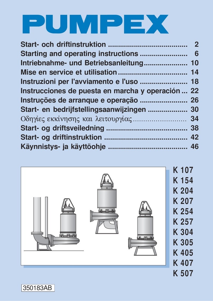
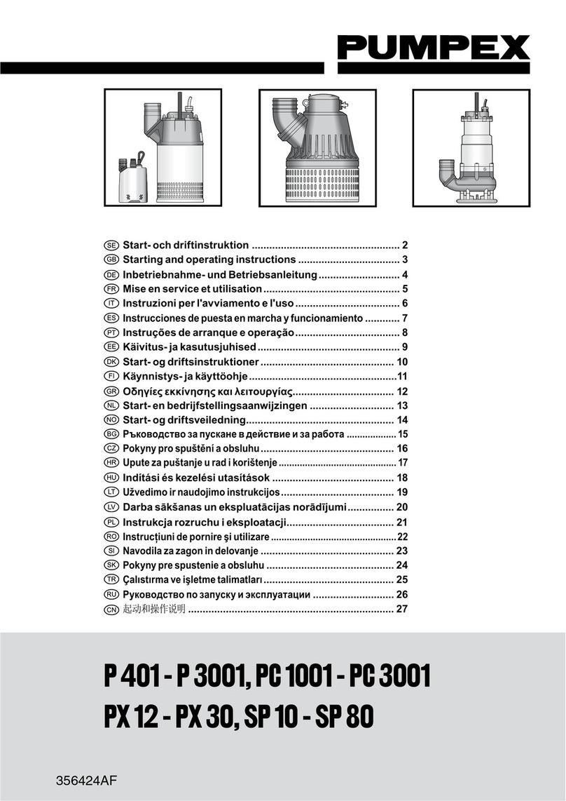
Pumpex K 80 How to use

Pumpex

Pumpex K 80 How to use

Pumpex K 107 How to use

Pumpex

Pumpex K 107 How to use

Pumpex P 601 Original operating manual

Pumpex

Pumpex P 601 Original operating manual

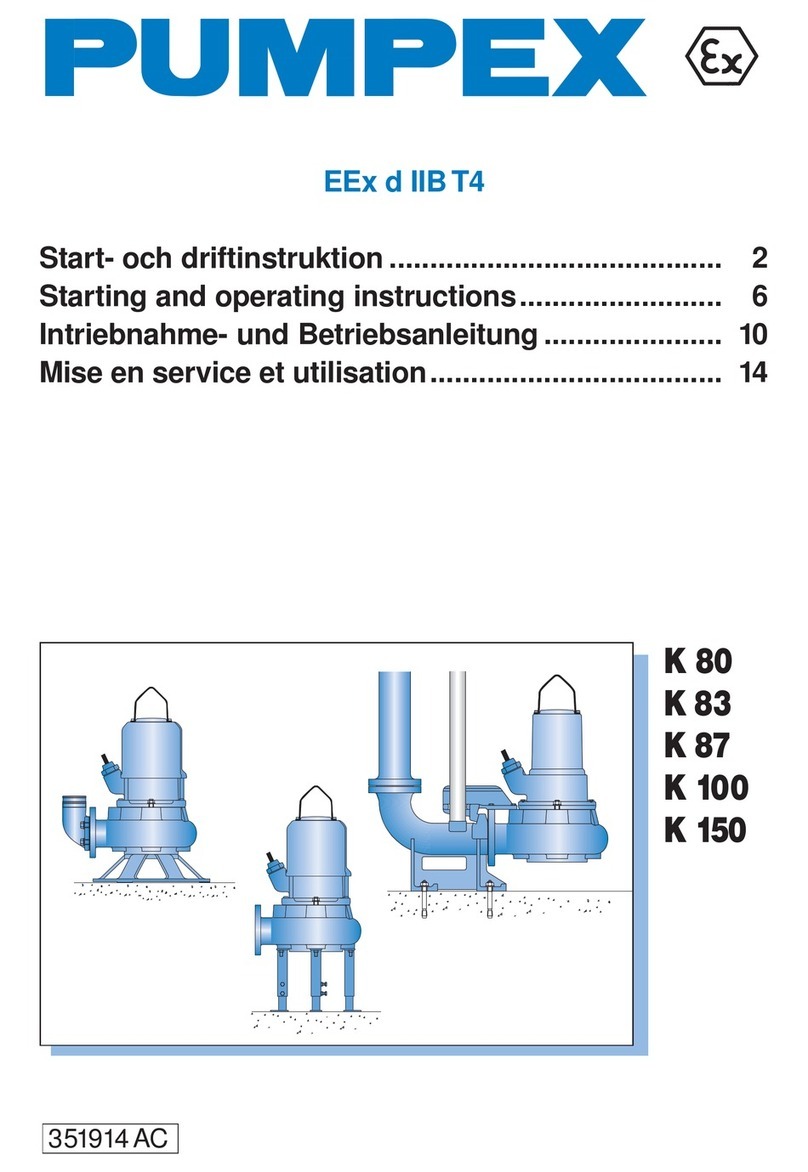
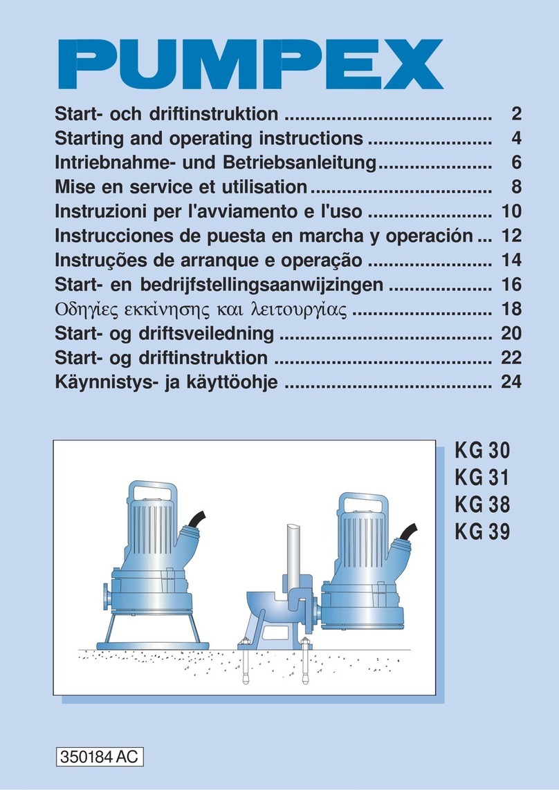
Pumpex K 101 Original operating manual
Pumpex

Pumpex K 101 Original operating manual

Popular Water Pump manuals by other brands

Reliable Equipment REL-GB-10 Operator's guide

Reliable Equipment

Reliable Equipment REL-GB-10 Operator's guide

Pentair MYERS MCI033 Installation and operation manual

Pentair

Pentair MYERS MCI033 Installation and operation manual

Xylem FLOJET M50 Installation, operation and maintenance manual

Xylem

Xylem FLOJET M50 Installation, operation and maintenance manual

Wilden P820 Engineering, operation & maintenance

Wilden

Wilden P820 Engineering, operation & maintenance

Pentair Fairbanks Nijhuis 2 Series Installation, operation and repair manual

Pentair

Pentair Fairbanks Nijhuis 2 Series Installation, operation and repair manual

Sicce XStream SDC instruction manual

Sicce

Sicce XStream SDC instruction manual

Gardner Denver WELCH CRVpro Series Operation manual

Gardner Denver

Gardner Denver WELCH CRVpro Series Operation manual

Master Pumps MPC750COMPACT Original instructions

Master Pumps

Master Pumps MPC750COMPACT Original instructions

Pfeiffer Vacuum HENA 202 operating instructions

Pfeiffer Vacuum

Pfeiffer Vacuum HENA 202 operating instructions

Barmesa Pumps BCS Series Installation, operation & maintenance manual

Barmesa Pumps

Barmesa Pumps BCS Series Installation, operation & maintenance manual

Sears Craftsman 390.269451 owner's manual

Sears

Sears Craftsman 390.269451 owner's manual

Graco Husky 2200 Operation

Graco

Graco Husky 2200 Operation

KSB UQD 112 operating instructions

KSB

KSB UQD 112 operating instructions

Wilo MultiVert-MVI 1 6 Series Installation and operating instructions

Wilo

Wilo MultiVert-MVI 1 6 Series Installation and operating instructions

Balcrank Lynx Series Operation, installation, maintenance and repair guide

Balcrank

Balcrank Lynx Series Operation, installation, maintenance and repair guide

ION SEF100M21 Operation manual

ION

ION SEF100M21 Operation manual

Ingersoll-Rand 650949-X Operator's manual

Ingersoll-Rand

Ingersoll-Rand 650949-X Operator's manual

GORMAN-RUPP PUMPS SF4C Installation, operation, and maintenance manual with parts list

GORMAN-RUPP PUMPS

GORMAN-RUPP PUMPS SF4C Installation, operation, and maintenance manual with parts list

manuals.online logo
manuals.online logoBrands
  • About & Mission
  • Contact us
  • Privacy Policy
  • Terms and Conditions

Copyright 2025 Manuals.Online. All Rights Reserved.