Purkeys TAPS User manual

INSTALLATION GUIDE
300-22 Doc 2.00
Trailer Auxiliary Power
System (TAPS)™


1
P: 479.419.4800 | F: 479.419.4801 | www.purkeys.net
CONTENTS
General Information ..........................................................................................2
System Diagram for Dual Pole Application....................................................3
System Diagram for Straight Truck Application............................................4
Dual Pole Conguration....................................................................................5
Straight Truck Conguration............................................................................5
Recommended Practices for Installation of TAPS Under the Trailer .........6
Mounting the TAPS Enclosure.........................................................................7
120 VAC Harness Installation...........................................................................8
Input Cable Routing for Dual Pole Application ...........................................12
Input Cable Routing for Straight Truck Application ...................................14
LED Indication and Operation.......................................................................16
Limited Commercial Warranty Policy...........................................................17

2
e Trailer Auxiliary Power System (TAPS)™ is designed to provide auxiliary
AC power at 120 volts in a trailer so that AC devices can be powered while
on the trailer. In this application, the AC power allows a device such as an
electric pallet jack to be charged while the truck is driving between stops. It
keeps the pallet jack at a high state of charge so it stays functional during the
hours of operation.
is trailer-based system receives DC power from the tractor via the dual
pole power cord. If mounted on a straight truck, it receives DC power from
the tractor batteries. TAPS converts DC power to 120 volt AC power and is
managed by a smart inverter that will not turn on until it sees a DC input of
13.2 volts.
Once the inverter turns on, it will stay on until the voltage drops below 12.4
volts for 30 seconds, or until the voltage drops below 10.5 volts. Once the
inverter turns o, it will not turn back on until the voltage again reaches at
least 13.2 volts.
GENERAL INFORMATION

3
P: 479.419.4800 | F: 479.419.4801 | www.purkeys.net
TAPS INSTALLATION GUIDE
SYSTEM DIAGRAM FOR
DUAL POLE APPLICATION
20' Dual pole
negative cable
Dual pole
positive cable
1500 Watt pure
sine inverter
Liquid tight 110 VAC harness
Reinforced nylon
receptacle box
110 VAC receptacle
with LED indication
Dual pole nosebox
x
INTERPRET THIS DRAWING IN ACCORDANCE WITH ASME
1.
Y14.100-2004
SEE SEPARATE PARTS LIST FOR PARTS
2.
REMOVE ALL BURRS
3.
BREAK SHARP CORNERS
4.
WEIGHT: -
5.
MATERIAL:
6.
MATERIAL FINISH:
7.
MATERIAL COLOR:
8.
TOLERANCES UNLESS OTHERWISE SPECIFIED:
IF ENGLISH AND METRIC SPECIFIED - ENGLISH [METRIC]
PROPRIETARY AND CONFIDENTIAL
THE INFORMATION CONTAINED IN THIS DRAWING IS THE SOLE
PROPERTY OF PURKEYS. ANY REPRODUCTION IN PART OR AS A WHOLE
WITHOUT THE WRITTEN PERMISSION OF PURKEYS IS PROHIBITED.
ENGLISH
.X
.030
.XX
.010
.XXX
.005
METRIC
.X
.25
.XX
.13
.XXX
.013
LOWELL, ARKANSAS 72745
DRAFT
3RD ANGLE
Peer Review Checklist:
Decal(s) (Buy Sticker)
•
Decal(s) included
•
No overlap
•
Correct tolerancing
•
Label(s) (Make Sticker)
•
Label(s)iIncluded
•
No overlap
•
Correct tolerancing
•
Serial # (if needed)
•
Appropriate location
•
Correct tolerancing
•
Correct sticker type
•
Work Order Barcode
•
Appropriate location
•
Correct tolerancing
•
Correct sticker type
•
Overall dimensions
•
Critical dimensions
•
Wire lengths
•
Appropriate tolerances on each sheet
•
Correct units are selected
•
Tolerances are appropriate
•
Weight
•
Weight includes everything in drawing
•
Units are shown
•
Important features
•
Complete title block (Based on PDM data card)
•
Description is accurate
•
Part number is correct
•
Project name is correct
•
Drawing number is correct
•
Revision is correct
•
Drawn By
shows correct name and date
•
Appropriate notes are included
•
First page shows entire part
•
BOM page(s) are complete and reflect
•
manufacturing process
Last page shows complete revision history
•
TECHNICAL DRAWING
Technical Drawing Checklists
- 2018/12/11
10111 - TAPS PURE SINE
PROJECT
PART #
CAGE:
DRAWN BY
REVIEWED BY
ENG APPR.
Q.A. APPR.
DATE
NAME
DESCRIPTION:
SIZE
B
DWG. NO.
REV
SCALE: 1:12
4/9/2019
SHEET 3 OF 6
PD009868
PART DESCRIPTION FILLS
FROM DATA CARD
A A
B B
C C
D D
E E
F F
10
10
9
9
8
8
7
7
6
6
5
5
4
4
3
3
2
2
1
1
Q.A. Approval Checklist:
Overall dimensions
•
Wire lengths
•
Complete title block
•
Description is accurate
•
Part number is correct
•
Project name is correct
•
Drawing number is correct
•
Revision is correct
•
Drawn By
,
Reviewed By
, and
Eng. Appr
show
•
correct names and dates
Tolerance units is selected on each sheet
•
First page shows entire part
•
BOM complete
•
Last page shows complete revision history
•
Watermark has been removed
•
Engineering Approval Checklist:
Correct Decal(s) and Label(s)
•
Correct graphic
•
All labels needed are shown
•
Serial # (if needed)
•
Appropriate location
•
Correct tolerancing
•
Correct sticker type
•
Work Order Barcode
•
Appropriate location
•
Correct tolerancing
•
Correct sticker type
•
Overall dimensions
•
Critical dimensions
•
Wire lengths
•
Weight
•
Weight includes everything in drawing
•
Units are shown
•
Important engineering/manufacturing/customer
•
features
Appropriate notes are included
•
First page shows entire part
•
Last page shows complete revision history
•
Reviewed By
shows correct name and date
•
BOM pages reflect correct manufacturing steps
•
NOTES:
### Be sure to press F7 to complete a spell check before you submit for Peer Review. ###
Components:
• Dual pole nosebox
• Dual pole positive (+)
• Dual pole negative (-)
• Inverter
• Liquid tight conduit with 110
VAC harness
• 110 V receptacle with power
indication
AC connections at the 4-terminal junction strip
15.20"
16.00"
22.50"
R.17"
.25"
2.00"
4.44"
x
INTERPRET THIS DRAWING IN ACCORDANCE WITH ASME
1.
Y14.100-2004
SEE SEPARATE PARTS LIST FOR PARTS
2.
REMOVE ALL BURRS
3.
BREAK SHARP CORNERS
4.
WEIGHT: -
5.
MATERIAL:
6.
MATERIAL FINISH:
7.
MATERIAL COLOR:
8.
TOLERANCES UNLESS OTHERWISE SPECIFIED:
IF ENGLISH AND METRIC SPECIFIED - ENGLISH [METRIC]
PROPRIETARY AND CONFIDENTIAL
THE INFORMATION CONTAINED IN THIS DRAWING IS THE SOLE
PROPERTY OF PURKEYS. ANY REPRODUCTION IN PART OR AS A WHOLE
WITHOUT THE WRITTEN PERMISSION OF PURKEYS IS PROHIBITED.
ENGLISH
.X
.030
.XX
.010
.XXX
.005
METRIC
.X
.25
.XX
.13
.XXX
.013
LOWELL, ARKANSAS 72745
DRAFT
3RD ANGLE
Peer Review Checklist:
Decal(s) (Buy Sticker)
•
Decal(s) included
•
No overlap
•
Correct tolerancing
•
Label(s) (Make Sticker)
•
Label(s)iIncluded
•
No overlap
•
Correct tolerancing
•
Serial # (if needed)
•
Appropriate location
•
Correct tolerancing
•
Correct sticker type
•
Work Order Barcode
•
Appropriate location
•
Correct tolerancing
•
Correct sticker type
•
Overall dimensions
•
Critical dimensions
•
Wire lengths
•
Appropriate tolerances on each sheet
•
Correct units are selected
•
Tolerances are appropriate
•
Weight
•
Weight includes everything in drawing
•
Units are shown
•
Important features
•
Complete title block (Based on PDM data card)
•
Description is accurate
•
Part number is correct
•
Project name is correct
•
Drawing number is correct
•
Revision is correct
•
Drawn By
shows correct name and date
•
Appropriate notes are included
•
First page shows entire part
•
BOM page(s) are complete and reflect
•
manufacturing process
Last page shows complete revision history
•
TECHNICAL DRAWING
Technical Drawing Checklists
- 2018/12/11
10111 - TAPS PURE SINE
PROJECT
PART #
CAGE:
DRAWN BY
REVIEWED BY
ENG APPR.
Q.A. APPR.
DATE
NAME
DESCRIPTION:
SIZE
B
DWG. NO.
REV
SCALE: 1:8
4/9/2019
SHEET 2 OF 6
PD009868
PART DESCRIPTION FILLS
FROM DATA CARD
A A
B B
C C
D D
E E
F F
10
10
9
9
8
8
7
7
6
6
5
5
4
4
3
3
2
2
1
1
Q.A. Approval Checklist:
Overall dimensions
•
Wire lengths
•
Complete title block
•
Description is accurate
•
Part number is correct
•
Project name is correct
•
Drawing number is correct
•
Revision is correct
•
Drawn By
,
Reviewed By
, and
Eng. Appr
show
•
correct names and dates
Tolerance units is selected on each sheet
•
First page shows entire part
•
BOM complete
•
Last page shows complete revision history
•
Watermark has been removed
•
Engineering Approval Checklist:
Correct Decal(s) and Label(s)
•
Correct graphic
•
All labels needed are shown
•
Serial # (if needed)
•
Appropriate location
•
Correct tolerancing
•
Correct sticker type
•
Work Order Barcode
•
Appropriate location
•
Correct tolerancing
•
Correct sticker type
•
Overall dimensions
•
Critical dimensions
•
Wire lengths
•
Weight
•
Weight includes everything in drawing
•
Units are shown
•
Important engineering/manufacturing/customer
•
features
Appropriate notes are included
•
First page shows entire part
•
Last page shows complete revision history
•
Reviewed By
shows correct name and date
•
BOM pages reflect correct manufacturing steps
•
NOTES:
### Be sure to press F7 to complete a spell check before you submit for Peer Review. ###

4
SYSTEM DIAGRAM FOR
STRAIGHT TRUCK APPLICATION
Components:
• 150 amp fuse cube and
bracket
• Dual pole positive (+)
• Dual pole negative (-)
• Inverter
• Liquid tight conduit with 110
VAC harness
• 110 V receptacle with power
indication
AC connections at the 4-terminal junction strip
'XDOSROH
QHJDWLYHFDEOH
'XDOSROH
SRVLWLYHFDEOH
:DWWSXUH
VLQHLQYHUWHU
/LTXLGWLJKW9$&KDUQHVV
5HLQIRUFHGQ\ORQ
UHFHSWDFOHER[
9$&UHFHSWDFOH
ZLWK/('LQGLFDWLRQ
'XDOSROHQRVHER[
[
,17(535(77+,6'5$:,1*,1$&&25'$1&(:,7+$60(
<
6((6(3$5$7(3$576/,67)253$576
5(029($//%8556
%5($.6+$53&251(56
:(,*+7
0$7(5,$/
0$7(5,$/),1,6+
0$7(5,$/&2/25
72/(5$1&(681/(6627+(5:,6(63(&,),('
,)(1*/,6+$1'0(75,&63(&,),('(1*/,6+>0(75,&@
35235,(7$5<$1'&21),'(17,$/
7+(,1)250$7,21&217$,1(',17+,6'5$:,1*,67+(62/(
3523(57<2)385.(<6$1<5(352'8&7,21,13$5725$6$:+2/(
:,7+2877+(:5,77(13(50,66,212)385.(<6,6352+,%,7('
(1*/,6+
;
;;
;;;
0(75,&
;
;;
;;;
/2:(//$5.$16$6
5'$1*/(
WĞĞƌZĞǀŝĞǁŚĞĐŬůŝƐƚ
ĞĐĂů;ƐͿ;ƵLJ^ƚŝĐŬĞƌͿ
ͻ
ĞĐĂů;ƐͿŝŶĐůƵĚĞĚ
ͻ
EŽŽǀĞƌůĂƉ
ͻ
ŽƌƌĞĐƚƚŽůĞƌĂŶĐŝŶŐ
ͻ
>ĂďĞů;ƐͿ;DĂŬĞ^ƚŝĐŬĞƌͿ
ͻ
>ĂďĞů;ƐͿŝ/ŶĐůƵĚĞĚ
ͻ
EŽŽǀĞƌůĂƉ
ͻ
ŽƌƌĞĐƚƚŽůĞƌĂŶĐŝŶŐ
ͻ
^ĞƌŝĂůη;ŝĨŶĞĞĚĞĚͿ
ͻ
ƉƉƌŽƉƌŝĂƚĞůŽĐĂƚŝŽŶ
ͻ
ŽƌƌĞĐƚƚŽůĞƌĂŶĐŝŶŐ
ͻ
ŽƌƌĞĐƚƐƚŝĐŬĞƌƚLJƉĞ
ͻ
tŽƌŬKƌĚĞƌĂƌĐŽĚĞ
ͻ
ƉƉƌŽƉƌŝĂƚĞůŽĐĂƚŝŽŶ
ͻ
ŽƌƌĞĐƚƚŽůĞƌĂŶĐŝŶŐ
ͻ
ŽƌƌĞĐƚƐƚŝĐŬĞƌƚLJƉĞ
ͻ
KǀĞƌĂůůĚŝŵĞŶƐŝŽŶƐ
ͻ
ƌŝƚŝĐĂůĚŝŵĞŶƐŝŽŶƐ
ͻ
tŝƌĞůĞŶŐƚŚƐ
ͻ
ƉƉƌŽƉƌŝĂƚĞƚŽůĞƌĂŶĐĞƐŽŶĞĂĐŚƐŚĞĞƚ
ͻ
ŽƌƌĞĐƚƵŶŝƚƐĂƌĞƐĞůĞĐƚĞĚ
ͻ
dŽůĞƌĂŶĐĞƐĂƌĞĂƉƉƌŽƉƌŝĂƚĞ
ͻ
tĞŝŐŚƚ
ͻ
tĞŝŐŚƚŝŶĐůƵĚĞƐĞǀĞƌLJƚŚŝŶŐŝŶĚƌĂǁŝŶŐ
ͻ
hŶŝƚƐĂƌĞƐŚŽǁŶ
ͻ
/ŵƉŽƌƚĂŶƚĨĞĂƚƵƌĞƐ
ͻ
ŽŵƉůĞƚĞƚŝƚůĞďůŽĐŬ;ĂƐĞĚŽŶWDĚĂƚĂĐĂƌĚͿ
ͻ
ĞƐĐƌŝƉƚŝŽŶŝƐĂĐĐƵƌĂƚĞ
ͻ
WĂƌƚŶƵŵďĞƌŝƐĐŽƌƌĞĐƚ
ͻ
WƌŽũĞĐƚŶĂŵĞŝƐĐŽƌƌĞĐƚ
ͻ
ƌĂǁŝŶŐŶƵŵďĞƌŝƐĐŽƌƌĞĐƚ
ͻ
ZĞǀŝƐŝŽŶŝƐĐŽƌƌĞĐƚ
ͻ
ƌĂǁŶLJ
ƐŚŽǁƐĐŽƌƌĞĐƚŶĂŵĞĂŶĚĚĂƚĞ
ͻ
ƉƉƌŽƉƌŝĂƚĞŶŽƚĞƐĂƌĞŝŶĐůƵĚĞĚ
ͻ
&ŝƌƐƚƉĂŐĞƐŚŽǁƐĞŶƚŝƌĞƉĂƌƚ
ͻ
KDƉĂŐĞ;ƐͿĂƌĞĐŽŵƉůĞƚĞĂŶĚƌĞĨůĞĐƚ
ͻ
ŵĂŶƵĨĂĐƚƵƌŝŶŐƉƌŽĐĞƐƐ
>ĂƐƚƉĂŐĞƐŚŽǁƐĐŽŵƉůĞƚĞƌĞǀŝƐŝŽŶŚŝƐƚŽƌLJ
ͻ
7(&+1,&$/'5$:,1*
dĞĐŚŶŝĐĂůƌĂǁŝŶŐŚĞĐŬůŝƐƚƐ
ͲϮϬϭϴϭϮϭϭ
7$36385(6,1(
352-(&7
3$57
&$*(
'5$:1%<
5(9,(:('%<
(1*$335
4$$335
'$7(
1$0(
'(6&5,37,21
6,=(
%
':*12
5(9
6&$/(
6+((72)
3'
3$57'(6&5,37,21),//6
)520'$7$&$5'
$ $
% %
& &
' '
( (
) )
YƉƉƌŽǀĂůŚĞĐŬůŝƐƚ
KǀĞƌĂůůĚŝŵĞŶƐŝŽŶƐ
ͻ
tŝƌĞůĞŶŐƚŚƐ
ͻ
ŽŵƉůĞƚĞƚŝƚůĞďůŽĐŬ
ͻ
ĞƐĐƌŝƉƚŝŽŶŝƐĂĐĐƵƌĂƚĞ
ͻ
WĂƌƚŶƵŵďĞƌŝƐĐŽƌƌĞĐƚ
ͻ
WƌŽũĞĐƚŶĂŵĞŝƐĐŽƌƌĞĐƚ
ͻ
ƌĂǁŝŶŐŶƵŵďĞƌŝƐĐŽƌƌĞĐƚ
ͻ
ZĞǀŝƐŝŽŶŝƐĐŽƌƌĞĐƚ
ͻ
ƌĂǁŶLJ
ZĞǀŝĞǁĞĚLJ
ĂŶĚ
ŶŐƉƉƌ
ƐŚŽǁ
ͻ
ĐŽƌƌĞĐƚŶĂŵĞƐĂŶĚĚĂƚĞƐ
dŽůĞƌĂŶĐĞƵŶŝƚƐŝƐƐĞůĞĐƚĞĚŽŶĞĂĐŚƐŚĞĞƚ
ͻ
&ŝƌƐƚƉĂŐĞƐŚŽǁƐĞŶƚŝƌĞƉĂƌƚ
ͻ
KDĐŽŵƉůĞƚĞ
ͻ
>ĂƐƚƉĂŐĞƐŚŽǁƐĐŽŵƉůĞƚĞƌĞǀŝƐŝŽŶŚŝƐƚŽƌLJ
ͻ
tĂƚĞƌŵĂƌŬŚĂƐďĞĞŶƌĞŵŽǀĞĚ
ͻ
ŶŐŝŶĞĞƌŝŶŐƉƉƌŽǀĂůŚĞĐŬůŝƐƚ
ŽƌƌĞĐƚĞĐĂů;ƐͿĂŶĚ>ĂďĞů;ƐͿ
ͻ
ŽƌƌĞĐƚŐƌĂƉŚŝĐ
ͻ
ůůůĂďĞůƐŶĞĞĚĞĚĂƌĞƐŚŽǁŶ
ͻ
^ĞƌŝĂůη;ŝĨŶĞĞĚĞĚͿ
ͻ
ƉƉƌŽƉƌŝĂƚĞůŽĐĂƚŝŽŶ
ͻ
ŽƌƌĞĐƚƚŽůĞƌĂŶĐŝŶŐ
ͻ
ŽƌƌĞĐƚƐƚŝĐŬĞƌƚLJƉĞ
ͻ
tŽƌŬKƌĚĞƌĂƌĐŽĚĞ
ͻ
ƉƉƌŽƉƌŝĂƚĞůŽĐĂƚŝŽŶ
ͻ
ŽƌƌĞĐƚƚŽůĞƌĂŶĐŝŶŐ
ͻ
ŽƌƌĞĐƚƐƚŝĐŬĞƌƚLJƉĞ
ͻ
KǀĞƌĂůůĚŝŵĞŶƐŝŽŶƐ
ͻ
ƌŝƚŝĐĂůĚŝŵĞŶƐŝŽŶƐ
ͻ
tŝƌĞůĞŶŐƚŚƐ
ͻ
tĞŝŐŚƚ
ͻ
tĞŝŐŚƚŝŶĐůƵĚĞƐĞǀĞƌLJƚŚŝŶŐŝŶĚƌĂǁŝŶŐ
ͻ
hŶŝƚƐĂƌĞƐŚŽǁŶ
ͻ
/ŵƉŽƌƚĂŶƚĞŶŐŝŶĞĞƌŝŶŐŵĂŶƵĨĂĐƚƵƌŝŶŐĐƵƐƚŽŵĞƌ
ͻ
ĨĞĂƚƵƌĞƐ
ƉƉƌŽƉƌŝĂƚĞŶŽƚĞƐĂƌĞŝŶĐůƵĚĞĚ
ͻ
&ŝƌƐƚƉĂŐĞƐŚŽǁƐĞŶƚŝƌĞƉĂƌƚ
ͻ
>ĂƐƚƉĂŐĞƐŚŽǁƐĐŽŵƉůĞƚĞƌĞǀŝƐŝŽŶŚŝƐƚŽƌLJ
ͻ
ZĞǀŝĞǁĞĚLJ
ƐŚŽǁƐĐŽƌƌĞĐƚŶĂŵĞĂŶĚĚĂƚĞ
ͻ
KDƉĂŐĞƐƌĞĨůĞĐƚĐŽƌƌĞĐƚŵĂŶƵĨĂĐƚƵƌŝŶŐƐƚĞƉƐ
ͻ
127(6
ηηηĞƐƵƌĞƚŽƉƌĞƐƐ&ϳƚŽĐŽŵƉůĞƚĞĂƐƉĞůůĐŚĞĐŬďĞĨŽƌĞLJŽƵƐƵďŵŝƚĨŽƌWĞĞƌZĞǀŝĞǁηηη
Fuse
150 amp
Fuse Cube
and
Bracket
15.20"
16.00"
22.50"
R.17"
.25"
2.00"
4.44"
x
INTERPRET THIS DRAWING IN ACCORDANCE WITH ASME
1.
Y14.100-2004
SEE SEPARATE PARTS LIST FOR PARTS
2.
REMOVE ALL BURRS
3.
BREAK SHARP CORNERS
4.
WEIGHT: -
5.
MATERIAL:
6.
MATERIAL FINISH:
7.
MATERIAL COLOR:
8.
TOLERANCES UNLESS OTHERWISE SPECIFIED:
IF ENGLISH AND METRIC SPECIFIED - ENGLISH [METRIC]
PROPRIETARY AND CONFIDENTIAL
THE INFORMATION CONTAINED IN THIS DRAWING IS THE SOLE
PROPERTY OF PURKEYS. ANY REPRODUCTION IN PART OR AS A WHOLE
WITHOUT THE WRITTEN PERMISSION OF PURKEYS IS PROHIBITED.
ENGLISH
.X
.030
.XX
.010
.XXX
.005
METRIC
.X
.25
.XX
.13
.XXX
.013
LOWELL, ARKANSAS 72745
DRAFT
3RD ANGLE
Peer Review Checklist:
Decal(s) (Buy Sticker)
•
Decal(s) included
•
No overlap
•
Correct tolerancing
•
Label(s) (Make Sticker)
•
Label(s)iIncluded
•
No overlap
•
Correct tolerancing
•
Serial # (if needed)
•
Appropriate location
•
Correct tolerancing
•
Correct sticker type
•
Work Order Barcode
•
Appropriate location
•
Correct tolerancing
•
Correct sticker type
•
Overall dimensions
•
Critical dimensions
•
Wire lengths
•
Appropriate tolerances on each sheet
•
Correct units are selected
•
Tolerances are appropriate
•
Weight
•
Weight includes everything in drawing
•
Units are shown
•
Important features
•
Complete title block (Based on PDM data card)
•
Description is accurate
•
Part number is correct
•
Project name is correct
•
Drawing number is correct
•
Revision is correct
•
Drawn By
shows correct name and date
•
Appropriate notes are included
•
First page shows entire part
•
BOM page(s) are complete and reflect
•
manufacturing process
Last page shows complete revision history
•
TECHNICAL DRAWING
Technical Drawing Checklists
- 2018/12/11
10111 - TAPS PURE SINE
PROJECT
PART #
CAGE:
DRAWN BY
REVIEWED BY
ENG APPR.
Q.A. APPR.
DATE
NAME
DESCRIPTION:
SIZE
B
DWG. NO.
REV
SCALE: 1:8
4/9/2019
SHEET 2 OF 6
PD009868
PART DESCRIPTION FILLS
FROM DATA CARD
A A
B B
C C
D D
E E
F F
10
10
9
9
8
8
7
7
6
6
5
5
4
4
3
3
2
2
1
1
Q.A. Approval Checklist:
Overall dimensions
•
Wire lengths
•
Complete title block
•
Description is accurate
•
Part number is correct
•
Project name is correct
•
Drawing number is correct
•
Revision is correct
•
Drawn By
,
Reviewed By
, and
Eng. Appr
show
•
correct names and dates
Tolerance units is selected on each sheet
•
First page shows entire part
•
BOM complete
•
Last page shows complete revision history
•
Watermark has been removed
•
Engineering Approval Checklist:
Correct Decal(s) and Label(s)
•
Correct graphic
•
All labels needed are shown
•
Serial # (if needed)
•
Appropriate location
•
Correct tolerancing
•
Correct sticker type
•
Work Order Barcode
•
Appropriate location
•
Correct tolerancing
•
Correct sticker type
•
Overall dimensions
•
Critical dimensions
•
Wire lengths
•
Weight
•
Weight includes everything in drawing
•
Units are shown
•
Important engineering/manufacturing/customer
•
features
Appropriate notes are included
•
First page shows entire part
•
Last page shows complete revision history
•
Reviewed By
shows correct name and date
•
BOM pages reflect correct manufacturing steps
•
NOTES:
### Be sure to press F7 to complete a spell check before you submit for Peer Review. ###

5
P: 479.419.4800 | F: 479.419.4801 | www.purkeys.net
TAPS INSTALLATION GUIDE
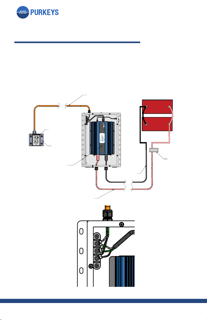
DUAL POLE CONFIGURATION
STRAIGHT TRUCK CONFIGURATION
'XDOSROH
QHJDWLYHFDEOH
'XDOSROH
SRVLWLYHFDEOH
:DWWSXUH
VLQHLQYHUWHU
/LTXLGWLJKW9$&KDUQHVV
5HLQIRUFHGQ\ORQ
UHFHSWDFOHER[
9$&UHFHSWDFOH
ZLWK/('LQGLFDWLRQ
'XDOSROHQRVHER[
[
,17(535(77+,6'5$:,1*,1$&&25'$1&(:,7+$60(
<
6((6(3$5$7(3$576/,67)253$576
5(029($//%8556
%5($.6+$53&251(56
:(,*+7
0$7(5,$/
0$7(5,$/),1,6+
0$7(5,$/&2/25
72/(5$1&(681/(6627+(5:,6(63(&,),('
,)(1*/,6+$1'0(75,&63(&,),('(1*/,6+>0(75,&@
35235,(7$5<$1'&21),'(17,$/
7+(,1)250$7,21&217$,1(',17+,6'5$:,1*,67+(62/(
3523(57<2)385.(<6$1<5(352'8&7,21,13$5725$6$:+2/(
:,7+2877+(:5,77(13(50,66,212)385.(<6,6352+,%,7('
(1*/,6+
;
;;
;;;
0(75,&
;
;;
;;;
/2:(//$5.$16$6
5'$1*/(
WĞĞƌZĞǀŝĞǁŚĞĐŬůŝƐƚ
ĞĐĂů;ƐͿ;ƵLJ^ƚŝĐŬĞƌͿ
ͻ
ĞĐĂů;ƐͿŝŶĐůƵĚĞĚ
ͻ
EŽŽǀĞƌůĂƉ
ͻ
ŽƌƌĞĐƚƚŽůĞƌĂŶĐŝŶŐ
ͻ
>ĂďĞů;ƐͿ;DĂŬĞ^ƚŝĐŬĞƌͿ
ͻ
>ĂďĞů;ƐͿŝ/ŶĐůƵĚĞĚ
ͻ
EŽŽǀĞƌůĂƉ
ͻ
ŽƌƌĞĐƚƚŽůĞƌĂŶĐŝŶŐ
ͻ
^ĞƌŝĂůη;ŝĨŶĞĞĚĞĚͿ
ͻ
ƉƉƌŽƉƌŝĂƚĞůŽĐĂƚŝŽŶ
ͻ
ŽƌƌĞĐƚƚŽůĞƌĂŶĐŝŶŐ
ͻ
ŽƌƌĞĐƚƐƚŝĐŬĞƌƚLJƉĞ
ͻ
tŽƌŬKƌĚĞƌĂƌĐŽĚĞ
ͻ
ƉƉƌŽƉƌŝĂƚĞůŽĐĂƚŝŽŶ
ͻ
ŽƌƌĞĐƚƚŽůĞƌĂŶĐŝŶŐ
ͻ
ŽƌƌĞĐƚƐƚŝĐŬĞƌƚLJƉĞ
ͻ
KǀĞƌĂůůĚŝŵĞŶƐŝŽŶƐ
ͻ
ƌŝƚŝĐĂůĚŝŵĞŶƐŝŽŶƐ
ͻ
tŝƌĞůĞŶŐƚŚƐ
ͻ
ƉƉƌŽƉƌŝĂƚĞƚŽůĞƌĂŶĐĞƐŽŶĞĂĐŚƐŚĞĞƚ
ͻ
ŽƌƌĞĐƚƵŶŝƚƐĂƌĞƐĞůĞĐƚĞĚ
ͻ
dŽůĞƌĂŶĐĞƐĂƌĞĂƉƉƌŽƉƌŝĂƚĞ
ͻ
tĞŝŐŚƚ
ͻ
tĞŝŐŚƚŝŶĐůƵĚĞƐĞǀĞƌLJƚŚŝŶŐŝŶĚƌĂǁŝŶŐ
ͻ
hŶŝƚƐĂƌĞƐŚŽǁŶ
ͻ
/ŵƉŽƌƚĂŶƚĨĞĂƚƵƌĞƐ
ͻ
ŽŵƉůĞƚĞƚŝƚůĞďůŽĐŬ;ĂƐĞĚŽŶWDĚĂƚĂĐĂƌĚͿ
ͻ
ĞƐĐƌŝƉƚŝŽŶŝƐĂĐĐƵƌĂƚĞ
ͻ
WĂƌƚŶƵŵďĞƌŝƐĐŽƌƌĞĐƚ
ͻ
WƌŽũĞĐƚŶĂŵĞŝƐĐŽƌƌĞĐƚ
ͻ
ƌĂǁŝŶŐŶƵŵďĞƌŝƐĐŽƌƌĞĐƚ
ͻ
ZĞǀŝƐŝŽŶŝƐĐŽƌƌĞĐƚ
ͻ
ƌĂǁŶLJ
ƐŚŽǁƐĐŽƌƌĞĐƚŶĂŵĞĂŶĚĚĂƚĞ
ͻ
ƉƉƌŽƉƌŝĂƚĞŶŽƚĞƐĂƌĞŝŶĐůƵĚĞĚ
ͻ
&ŝƌƐƚƉĂŐĞƐŚŽǁƐĞŶƚŝƌĞƉĂƌƚ
ͻ
KDƉĂŐĞ;ƐͿĂƌĞĐŽŵƉůĞƚĞĂŶĚƌĞĨůĞĐƚ
ͻ
ŵĂŶƵĨĂĐƚƵƌŝŶŐƉƌŽĐĞƐƐ
>ĂƐƚƉĂŐĞƐŚŽǁƐĐŽŵƉůĞƚĞƌĞǀŝƐŝŽŶŚŝƐƚŽƌLJ
ͻ
7(&+1,&$/'5$:,1*
dĞĐŚŶŝĐĂůƌĂǁŝŶŐŚĞĐŬůŝƐƚƐ
ͲϮϬϭϴϭϮϭϭ
7$36385(6,1(
352-(&7
3$57
&$*(
'5$:1%<
5(9,(:('%<
(1*$335
4$$335
'$7(
1$0(
'(6&5,37,21
6,=(
%
':*12
5(9
6&$/(
6+((72)
3'
3$57'(6&5,37,21),//6
)520'$7$&$5'
$ $
% %
& &
' '
( (
) )
YƉƉƌŽǀĂůŚĞĐŬůŝƐƚ
KǀĞƌĂůůĚŝŵĞŶƐŝŽŶƐ
ͻ
tŝƌĞůĞŶŐƚŚƐ
ͻ
ŽŵƉůĞƚĞƚŝƚůĞďůŽĐŬ
ͻ
ĞƐĐƌŝƉƚŝŽŶŝƐĂĐĐƵƌĂƚĞ
ͻ
WĂƌƚŶƵŵďĞƌŝƐĐŽƌƌĞĐƚ
ͻ
WƌŽũĞĐƚŶĂŵĞŝƐĐŽƌƌĞĐƚ
ͻ
ƌĂǁŝŶŐŶƵŵďĞƌŝƐĐŽƌƌĞĐƚ
ͻ
ZĞǀŝƐŝŽŶŝƐĐŽƌƌĞĐƚ
ͻ
ƌĂǁŶLJ
ZĞǀŝĞǁĞĚLJ
ĂŶĚ
ŶŐƉƉƌ
ƐŚŽǁ
ͻ
ĐŽƌƌĞĐƚŶĂŵĞƐĂŶĚĚĂƚĞƐ
dŽůĞƌĂŶĐĞƵŶŝƚƐŝƐƐĞůĞĐƚĞĚŽŶĞĂĐŚƐŚĞĞƚ
ͻ
&ŝƌƐƚƉĂŐĞƐŚŽǁƐĞŶƚŝƌĞƉĂƌƚ
ͻ
KDĐŽŵƉůĞƚĞ
ͻ
>ĂƐƚƉĂŐĞƐŚŽǁƐĐŽŵƉůĞƚĞƌĞǀŝƐŝŽŶŚŝƐƚŽƌLJ
ͻ
tĂƚĞƌŵĂƌŬŚĂƐďĞĞŶƌĞŵŽǀĞĚ
ͻ
ŶŐŝŶĞĞƌŝŶŐƉƉƌŽǀĂůŚĞĐŬůŝƐƚ
ŽƌƌĞĐƚĞĐĂů;ƐͿĂŶĚ>ĂďĞů;ƐͿ
ͻ
ŽƌƌĞĐƚŐƌĂƉŚŝĐ
ͻ
ůůůĂďĞůƐŶĞĞĚĞĚĂƌĞƐŚŽǁŶ
ͻ
^ĞƌŝĂůη;ŝĨŶĞĞĚĞĚͿ
ͻ
ƉƉƌŽƉƌŝĂƚĞůŽĐĂƚŝŽŶ
ͻ
ŽƌƌĞĐƚƚŽůĞƌĂŶĐŝŶŐ
ͻ
ŽƌƌĞĐƚƐƚŝĐŬĞƌƚLJƉĞ
ͻ
tŽƌŬKƌĚĞƌĂƌĐŽĚĞ
ͻ
ƉƉƌŽƉƌŝĂƚĞůŽĐĂƚŝŽŶ
ͻ
ŽƌƌĞĐƚƚŽůĞƌĂŶĐŝŶŐ
ͻ
ŽƌƌĞĐƚƐƚŝĐŬĞƌƚLJƉĞ
ͻ
KǀĞƌĂůůĚŝŵĞŶƐŝŽŶƐ
ͻ
ƌŝƚŝĐĂůĚŝŵĞŶƐŝŽŶƐ
ͻ
tŝƌĞůĞŶŐƚŚƐ
ͻ
tĞŝŐŚƚ
ͻ
tĞŝŐŚƚŝŶĐůƵĚĞƐĞǀĞƌLJƚŚŝŶŐŝŶĚƌĂǁŝŶŐ
ͻ
hŶŝƚƐĂƌĞƐŚŽǁŶ
ͻ
/ŵƉŽƌƚĂŶƚĞŶŐŝŶĞĞƌŝŶŐŵĂŶƵĨĂĐƚƵƌŝŶŐĐƵƐƚŽŵĞƌ
ͻ
ĨĞĂƚƵƌĞƐ
ƉƉƌŽƉƌŝĂƚĞŶŽƚĞƐĂƌĞŝŶĐůƵĚĞĚ
ͻ
&ŝƌƐƚƉĂŐĞƐŚŽǁƐĞŶƚŝƌĞƉĂƌƚ
ͻ
>ĂƐƚƉĂŐĞƐŚŽǁƐĐŽŵƉůĞƚĞƌĞǀŝƐŝŽŶŚŝƐƚŽƌLJ
ͻ
ZĞǀŝĞǁĞĚLJ
ƐŚŽǁƐĐŽƌƌĞĐƚŶĂŵĞĂŶĚĚĂƚĞ
ͻ
KDƉĂŐĞƐƌĞĨůĞĐƚĐŽƌƌĞĐƚŵĂŶƵĨĂĐƚƵƌŝŶŐƐƚĞƉƐ
ͻ
127(6
ηηηĞƐƵƌĞƚŽƉƌĞƐƐ&ϳƚŽĐŽŵƉůĞƚĞĂƐƉĞůůĐŚĞĐŬďĞĨŽƌĞLJŽƵƐƵďŵŝƚĨŽƌWĞĞƌZĞǀŝĞǁηηη
Fuse
150 amp
Fuse Cube
and
Bracket
x
INTERPRET THIS DRAWING IN ACCORDANCE WITH ASME
1.
Y14.100-2004
SEE SEPARATE PARTS LIST FOR PARTS
2.
REMOVE ALL BURRS
3.
BREAK SHARP CORNERS
4.
WEIGHT: -
5.
MATERIAL:
6.
MATERIAL FINISH:
7.
MATERIAL COLOR:
8.
TOLERANCES UNLESS OTHERWISE SPECIFIED:
IF ENGLISH AND METRIC SPECIFIED - ENGLISH [METRIC]
PROPRIETARY AND CONFIDENTIAL
THE INFORMATION CONTAINED IN THIS DRAWING IS THE SOLE
PROPERTY OF PURKEYS. ANY REPRODUCTION IN PART OR AS A WHOLE
WITHOUT THE WRITTEN PERMISSION OF PURKEYS IS PROHIBITED.
ENGLISH
.X
.030
.XX
.010
.XXX
.005
METRIC
.X
.25
.XX
.13
.XXX
.013
LOWELL, ARKANSAS 72745
DRAFT
3RD ANGLE
Peer Review Checklist:
Decal(s) (Buy Sticker)
•
Decal(s) included
•
No overlap
•
Correct tolerancing
•
Label(s) (Make Sticker)
•
Label(s)iIncluded
•
No overlap
•
Correct tolerancing
•
Serial # (if needed)
•
Appropriate location
•
Correct tolerancing
•
Correct sticker type
•
Work Order Barcode
•
Appropriate location
•
Correct tolerancing
•
Correct sticker type
•
Overall dimensions
•
Critical dimensions
•
Wire lengths
•
Appropriate tolerances on each sheet
•
Correct units are selected
•
Tolerances are appropriate
•
Weight
•
Weight includes everything in drawing
•
Units are shown
•
Important features
•
Complete title block (Based on PDM data card)
•
Description is accurate
•
Part number is correct
•
Project name is correct
•
Drawing number is correct
•
Revision is correct
•
Drawn By
shows correct name and date
•
Appropriate notes are included
•
First page shows entire part
•
BOM page(s) are complete and reflect
•
manufacturing process
Last page shows complete revision history
•
TECHNICAL DRAWING
Technical Drawing Checklists
- 2018/12/11
10111 - TAPS PURE SINE
PROJECT
PART #
CAGE:
DRAWN BY
REVIEWED BY
ENG APPR.
Q.A. APPR.
DATE
NAME
DESCRIPTION:
SIZE
B
DWG. NO.
REV
SCALE: 1:8
4/9/2019
SHEET 1 OF 6
PD009868
PART DESCRIPTION FILLS
FROM DATA CARD
A A
B B
C C
D D
E E
F F
10
10
9
9
8
8
7
7
6
6
5
5
4
4
3
3
2
2
1
1
Q.A. Approval Checklist:
Overall dimensions
•
Wire lengths
•
Complete title block
•
Description is accurate
•
Part number is correct
•
Project name is correct
•
Drawing number is correct
•
Revision is correct
•
Drawn By
,
Reviewed By
, and
Eng. Appr
show
•
correct names and dates
Tolerance units is selected on each sheet
•
First page shows entire part
•
BOM complete
•
Last page shows complete revision history
•
Watermark has been removed
•
Engineering Approval Checklist:
Correct Decal(s) and Label(s)
•
Correct graphic
•
All labels needed are shown
•
Serial # (if needed)
•
Appropriate location
•
Correct tolerancing
•
Correct sticker type
•
Work Order Barcode
•
Appropriate location
•
Correct tolerancing
•
Correct sticker type
•
Overall dimensions
•
Critical dimensions
•
Wire lengths
•
Weight
•
Weight includes everything in drawing
•
Units are shown
•
Important engineering/manufacturing/customer
•
features
Appropriate notes are included
•
First page shows entire part
•
Last page shows complete revision history
•
Reviewed By
shows correct name and date
•
BOM pages reflect correct manufacturing steps
•
NOTES:
### Be sure to press F7 to complete a spell check before you submit for Peer Review. ###
'XDOSROH
QHJDWLYHFDEOH
'XDOSROH
SRVLWLYHFDEOH
:DWWSXUH
VLQHLQYHUWHU
/LTXLGWLJKW9$&KDUQHVV
5HLQIRUFHGQ\ORQ
UHFHSWDFOHER[
9$&UHFHSWDFOH
ZLWK/('LQGLFDWLRQ
'XDOSROHQRVHER[
[
,17(535(77+,6'5$:,1*,1$&&25'$1&(:,7+$60(
<
6((6(3$5$7(3$576/,67)253$576
5(029($//%8556
%5($.6+$53&251(56
:(,*+7
0$7(5,$/
0$7(5,$/),1,6+
0$7(5,$/&2/25
72/(5$1&(681/(6627+(5:,6(63(&,),('
,)(1*/,6+$1'0(75,&63(&,),('(1*/,6+>0(75,&@
35235,(7$5<$1'&21),'(17,$/
7+(,1)250$7,21&217$,1(',17+,6'5$:,1*,67+(62/(
3523(57<2)385.(<6$1<5(352'8&7,21,13$5725$6$:+2/(
:,7+2877+(:5,77(13(50,66,212)385.(<6,6352+,%,7('
(1*/,6+
;
;;
;;;
0(75,&
;
;;
;;;
/2:(//$5.$16$6
5'$1*/(
WĞĞƌZĞǀŝĞǁŚĞĐŬůŝƐƚ
ĞĐĂů;ƐͿ;ƵLJ^ƚŝĐŬĞƌͿ
ͻ
ĞĐĂů;ƐͿŝŶĐůƵĚĞĚ
ͻ
EŽŽǀĞƌůĂƉ
ͻ
ŽƌƌĞĐƚƚŽůĞƌĂŶĐŝŶŐ
ͻ
>ĂďĞů;ƐͿ;DĂŬĞ^ƚŝĐŬĞƌͿ
ͻ
>ĂďĞů;ƐͿŝ/ŶĐůƵĚĞĚ
ͻ
EŽŽǀĞƌůĂƉ
ͻ
ŽƌƌĞĐƚƚŽůĞƌĂŶĐŝŶŐ
ͻ
^ĞƌŝĂůη;ŝĨŶĞĞĚĞĚͿ
ͻ
ƉƉƌŽƉƌŝĂƚĞůŽĐĂƚŝŽŶ
ͻ
ŽƌƌĞĐƚƚŽůĞƌĂŶĐŝŶŐ
ͻ
ŽƌƌĞĐƚƐƚŝĐŬĞƌƚLJƉĞ
ͻ
tŽƌŬKƌĚĞƌĂƌĐŽĚĞ
ͻ
ƉƉƌŽƉƌŝĂƚĞůŽĐĂƚŝŽŶ
ͻ
ŽƌƌĞĐƚƚŽůĞƌĂŶĐŝŶŐ
ͻ
ŽƌƌĞĐƚƐƚŝĐŬĞƌƚLJƉĞ
ͻ
KǀĞƌĂůůĚŝŵĞŶƐŝŽŶƐ
ͻ
ƌŝƚŝĐĂůĚŝŵĞŶƐŝŽŶƐ
ͻ
tŝƌĞůĞŶŐƚŚƐ
ͻ
ƉƉƌŽƉƌŝĂƚĞƚŽůĞƌĂŶĐĞƐŽŶĞĂĐŚƐŚĞĞƚ
ͻ
ŽƌƌĞĐƚƵŶŝƚƐĂƌĞƐĞůĞĐƚĞĚ
ͻ
dŽůĞƌĂŶĐĞƐĂƌĞĂƉƉƌŽƉƌŝĂƚĞ
ͻ
tĞŝŐŚƚ
ͻ
tĞŝŐŚƚŝŶĐůƵĚĞƐĞǀĞƌLJƚŚŝŶŐŝŶĚƌĂǁŝŶŐ
ͻ
hŶŝƚƐĂƌĞƐŚŽǁŶ
ͻ
/ŵƉŽƌƚĂŶƚĨĞĂƚƵƌĞƐ
ͻ
ŽŵƉůĞƚĞƚŝƚůĞďůŽĐŬ;ĂƐĞĚŽŶWDĚĂƚĂĐĂƌĚͿ
ͻ
ĞƐĐƌŝƉƚŝŽŶŝƐĂĐĐƵƌĂƚĞ
ͻ
WĂƌƚŶƵŵďĞƌŝƐĐŽƌƌĞĐƚ
ͻ
WƌŽũĞĐƚŶĂŵĞŝƐĐŽƌƌĞĐƚ
ͻ
ƌĂǁŝŶŐŶƵŵďĞƌŝƐĐŽƌƌĞĐƚ
ͻ
ZĞǀŝƐŝŽŶŝƐĐŽƌƌĞĐƚ
ͻ
ƌĂǁŶLJ
ƐŚŽǁƐĐŽƌƌĞĐƚŶĂŵĞĂŶĚĚĂƚĞ
ͻ
ƉƉƌŽƉƌŝĂƚĞŶŽƚĞƐĂƌĞŝŶĐůƵĚĞĚ
ͻ
&ŝƌƐƚƉĂŐĞƐŚŽǁƐĞŶƚŝƌĞƉĂƌƚ
ͻ
KDƉĂŐĞ;ƐͿĂƌĞĐŽŵƉůĞƚĞĂŶĚƌĞĨůĞĐƚ
ͻ
ŵĂŶƵĨĂĐƚƵƌŝŶŐƉƌŽĐĞƐƐ
>ĂƐƚƉĂŐĞƐŚŽǁƐĐŽŵƉůĞƚĞƌĞǀŝƐŝŽŶŚŝƐƚŽƌLJ
ͻ
7(&+1,&$/'5$:,1*
dĞĐŚŶŝĐĂůƌĂǁŝŶŐŚĞĐŬůŝƐƚƐ
ͲϮϬϭϴϭϮϭϭ
7$36385(6,1(
352-(&7
3$57
&$*(
'5$:1%<
5(9,(:('%<
(1*$335
4$$335
'$7(
1$0(
'(6&5,37,21
6,=(
%
':*12
5(9
6&$/(
6+((72)
3'
3$57'(6&5,37,21),//6
)520'$7$&$5'
$ $
% %
& &
' '
( (
) )
YƉƉƌŽǀĂůŚĞĐŬůŝƐƚ
KǀĞƌĂůůĚŝŵĞŶƐŝŽŶƐ
ͻ
tŝƌĞůĞŶŐƚŚƐ
ͻ
ŽŵƉůĞƚĞƚŝƚůĞďůŽĐŬ
ͻ
ĞƐĐƌŝƉƚŝŽŶŝƐĂĐĐƵƌĂƚĞ
ͻ
WĂƌƚŶƵŵďĞƌŝƐĐŽƌƌĞĐƚ
ͻ
WƌŽũĞĐƚŶĂŵĞŝƐĐŽƌƌĞĐƚ
ͻ
ƌĂǁŝŶŐŶƵŵďĞƌŝƐĐŽƌƌĞĐƚ
ͻ
ZĞǀŝƐŝŽŶŝƐĐŽƌƌĞĐƚ
ͻ
ƌĂǁŶLJ
ZĞǀŝĞǁĞĚLJ
ĂŶĚ
ŶŐƉƉƌ
ƐŚŽǁ
ͻ
ĐŽƌƌĞĐƚŶĂŵĞƐĂŶĚĚĂƚĞƐ
dŽůĞƌĂŶĐĞƵŶŝƚƐŝƐƐĞůĞĐƚĞĚŽŶĞĂĐŚƐŚĞĞƚ
ͻ
&ŝƌƐƚƉĂŐĞƐŚŽǁƐĞŶƚŝƌĞƉĂƌƚ
ͻ
KDĐŽŵƉůĞƚĞ
ͻ
>ĂƐƚƉĂŐĞƐŚŽǁƐĐŽŵƉůĞƚĞƌĞǀŝƐŝŽŶŚŝƐƚŽƌLJ
ͻ
tĂƚĞƌŵĂƌŬŚĂƐďĞĞŶƌĞŵŽǀĞĚ
ͻ
ŶŐŝŶĞĞƌŝŶŐƉƉƌŽǀĂůŚĞĐŬůŝƐƚ
ŽƌƌĞĐƚĞĐĂů;ƐͿĂŶĚ>ĂďĞů;ƐͿ
ͻ
ŽƌƌĞĐƚŐƌĂƉŚŝĐ
ͻ
ůůůĂďĞůƐŶĞĞĚĞĚĂƌĞƐŚŽǁŶ
ͻ
^ĞƌŝĂůη;ŝĨŶĞĞĚĞĚͿ
ͻ
ƉƉƌŽƉƌŝĂƚĞůŽĐĂƚŝŽŶ
ͻ
ŽƌƌĞĐƚƚŽůĞƌĂŶĐŝŶŐ
ͻ
ŽƌƌĞĐƚƐƚŝĐŬĞƌƚLJƉĞ
ͻ
tŽƌŬKƌĚĞƌĂƌĐŽĚĞ
ͻ
ƉƉƌŽƉƌŝĂƚĞůŽĐĂƚŝŽŶ
ͻ
ŽƌƌĞĐƚƚŽůĞƌĂŶĐŝŶŐ
ͻ
ŽƌƌĞĐƚƐƚŝĐŬĞƌƚLJƉĞ
ͻ
KǀĞƌĂůůĚŝŵĞŶƐŝŽŶƐ
ͻ
ƌŝƚŝĐĂůĚŝŵĞŶƐŝŽŶƐ
ͻ
tŝƌĞůĞŶŐƚŚƐ
ͻ
tĞŝŐŚƚ
ͻ
tĞŝŐŚƚŝŶĐůƵĚĞƐĞǀĞƌLJƚŚŝŶŐŝŶĚƌĂǁŝŶŐ
ͻ
hŶŝƚƐĂƌĞƐŚŽǁŶ
ͻ
/ŵƉŽƌƚĂŶƚĞŶŐŝŶĞĞƌŝŶŐŵĂŶƵĨĂĐƚƵƌŝŶŐĐƵƐƚŽŵĞƌ
ͻ
ĨĞĂƚƵƌĞƐ
ƉƉƌŽƉƌŝĂƚĞŶŽƚĞƐĂƌĞŝŶĐůƵĚĞĚ
ͻ
&ŝƌƐƚƉĂŐĞƐŚŽǁƐĞŶƚŝƌĞƉĂƌƚ
ͻ
>ĂƐƚƉĂŐĞƐŚŽǁƐĐŽŵƉůĞƚĞƌĞǀŝƐŝŽŶŚŝƐƚŽƌLJ
ͻ
ZĞǀŝĞǁĞĚLJ
ƐŚŽǁƐĐŽƌƌĞĐƚŶĂŵĞĂŶĚĚĂƚĞ
ͻ
KDƉĂŐĞƐƌĞĨůĞĐƚĐŽƌƌĞĐƚŵĂŶƵĨĂĐƚƵƌŝŶŐƐƚĞƉƐ
ͻ
127(6
ηηηĞƐƵƌĞƚŽƉƌĞƐƐ&ϳƚŽĐŽŵƉůĞƚĞĂƐƉĞůůĐŚĞĐŬďĞĨŽƌĞLJŽƵƐƵďŵŝƚĨŽƌWĞĞƌZĞǀŝĞǁηηη
Fuse
150 amp
Fuse Cube
and
Bracket

6
1. Do NOT use self-tapping hardware
2. Hardware must be 5/16”-18 SS screws (we highly recommend using
provided hardware).
3. Lock nut hardware MUST be used. e material must be stainless steel
(we highly recommend using provided hardware).
4. e TAPS has been designed to be fastened to a trailer’s load-bearing
beams.
5. At LEAST 4 points of contact (6 are preferred) must be fastened between
the TAPS enclosure and support (i.e., trailer beams, mounting plate,
etc.).
6. Fastening hardware must be tightened to proper torque specication (22
Ft/Lbs. with lube, 29 Ft/Lbs. dry).
7. We encourage, but do not require, the use of a medium-strength Loctite
thread locker during installation. We do NOT recommend high-strength
thread locker (Loctite Red) as the enclosure may need to be removed.
8. Mount the TAPS enclosure as close to the power source as possible for
best performance.
9. Route 2/0 red and black cables in a manner that mitigates chang (avoid
sharp/rough surfaces).
10.Route the AC output harness (orange liquid-tight) in a manner that
will not allow it to be struck, bent, or damaged by standard operating
proceedures.
RECOMMENDED PRACTICES FOR
INSTALLATION OF TAPS UNDER THE TRAILER
Read all practices before beginning install to avoid
voiding warranty.

7
P: 479.419.4800 | F: 479.419.4801 | www.purkeys.net
TAPS INSTALLATION GUIDE
MOUNTING THE TAPS ENCLOSURE
Step 1: Mount the TAPS enclosure
in a suitable location, either inside
or outside of the trailer, using the
universal mounting brackets.
TAPS enclosure mounting complete.
15.20"
16.00"
22.50"
R.17"
.25"
2.00"
4.44"
x
INTERPRET THIS DRAWING IN ACCORDANCE WITH ASME
1.
Y14.100-2004
SEE SEPARATE PARTS LIST FOR PARTS
2.
REMOVE ALL BURRS
3.
BREAK SHARP CORNERS
4.
WEIGHT: -
5.
MATERIAL:
6.
MATERIAL FINISH:
7.
MATERIAL COLOR:
8.
TOLERANCES UNLESS OTHERWISE SPECIFIED:
IF ENGLISH AND METRIC SPECIFIED - ENGLISH [METRIC]
PROPRIETARY AND CONFIDENTIAL
THE INFORMATION CONTAINED IN THIS DRAWING IS THE SOLE
PROPERTY OF PURKEYS. ANY REPRODUCTION IN PART OR AS A WHOLE
WITHOUT THE WRITTEN PERMISSION OF PURKEYS IS PROHIBITED.
ENGLISH
.X
.030
.XX
.010
.XXX
.005
METRIC
.X
.25
.XX
.13
.XXX
.013
LOWELL, ARKANSAS 72745
DRAFT
3RD ANGLE
Peer Review Checklist:
Decal(s) (Buy Sticker)
•
Decal(s) included
•
No overlap
•
Correct tolerancing
•
Label(s) (Make Sticker)
•
Label(s)iIncluded
•
No overlap
•
Correct tolerancing
•
Serial # (if needed)
•
Appropriate location
•
Correct tolerancing
•
Correct sticker type
•
Work Order Barcode
•
Appropriate location
•
Correct tolerancing
•
Correct sticker type
•
Overall dimensions
•
Critical dimensions
•
Wire lengths
•
Appropriate tolerances on each sheet
•
Correct units are selected
•
Tolerances are appropriate
•
Weight
•
Weight includes everything in drawing
•
Units are shown
•
Important features
•
Complete title block (Based on PDM data card)
•
Description is accurate
•
Part number is correct
•
Project name is correct
•
Drawing number is correct
•
Revision is correct
•
Drawn By
shows correct name and date
•
Appropriate notes are included
•
First page shows entire part
•
BOM page(s) are complete and reflect
•
manufacturing process
Last page shows complete revision history
•
TECHNICAL DRAWING
Technical Drawing Checklists
- 2018/12/11
10111 - TAPS PURE SINE
PROJECT
PART #
CAGE:
DRAWN BY
REVIEWED BY
ENG APPR.
Q.A. APPR.
DATE
NAME
DESCRIPTION:
SIZE
B
DWG. NO.
REV
SCALE: 1:8
4/9/2019
SHEET 2 OF 6
PD009868
PART DESCRIPTION FILLS
FROM DATA CARD
A A
B B
C C
D D
E E
F F
10
10
9
9
8
8
7
7
6
6
5
5
4
4
3
3
2
2
1
1
Q.A. Approval Checklist:
Overall dimensions
•
Wire lengths
•
Complete title block
•
Description is accurate
•
Part number is correct
•
Project name is correct
•
Drawing number is correct
•
Revision is correct
•
Drawn By
,
Reviewed By
, and
Eng. Appr
show
•
correct names and dates
Tolerance units is selected on each sheet
•
First page shows entire part
•
BOM complete
•
Last page shows complete revision history
•
Watermark has been removed
•
Engineering Approval Checklist:
Correct Decal(s) and Label(s)
•
Correct graphic
•
All labels needed are shown
•
Serial # (if needed)
•
Appropriate location
•
Correct tolerancing
•
Correct sticker type
•
Work Order Barcode
•
Appropriate location
•
Correct tolerancing
•
Correct sticker type
•
Overall dimensions
•
Critical dimensions
•
Wire lengths
•
Weight
•
Weight includes everything in drawing
•
Units are shown
•
Important engineering/manufacturing/customer
•
features
Appropriate notes are included
•
First page shows entire part
•
Last page shows complete revision history
•
Reviewed By
shows correct name and date
•
BOM pages reflect correct manufacturing steps
•
NOTES:
### Be sure to press F7 to complete a spell check before you submit for Peer Review. ###

8
120 VAC HARNESS INSTALLATION
Step 1: Route the end of the 120
VAC harness that contains the
three wires with the #10 eyelets
through the hole at the top of
the TAPS enclosure. Secure the
harness to the enclosure using the
supplied liquid-tight tting.
Step 2: Attach the white wire from
the harness to the white wire on
the stud, the green wire to the
green wire, and the black wire to
the black wire.
Important! To reduce the risk of electrical shock, make sure the inverter
does not have power before making the following connections.
Step 3: Once the connections are
complete, close the lid, then install
all 8 lid screws (included). Torque
to 5 lb-in. DO NOT exceed 7 lb-in
or screws can be damaged.
15.20"
16.00"
22.50"
R.17"
.25"
2.00"
4.44"
x
INTERPRET THIS DRAWING IN ACCORDANCE WITH ASME
1.
Y14.100-2004
SEE SEPARATE PARTS LIST FOR PARTS
2.
REMOVE ALL BURRS
3.
BREAK SHARP CORNERS
4.
WEIGHT: -
5.
MATERIAL:
6.
MATERIAL FINISH:
7.
MATERIAL COLOR:
8.
TOLERANCES UNLESS OTHERWISE SPECIFIED:
IF ENGLISH AND METRIC SPECIFIED - ENGLISH [METRIC]
PROPRIETARY AND CONFIDENTIAL
THE INFORMATION CONTAINED IN THIS DRAWING IS THE SOLE
PROPERTY OF PURKEYS. ANY REPRODUCTION IN PART OR AS A WHOLE
WITHOUT THE WRITTEN PERMISSION OF PURKEYS IS PROHIBITED.
ENGLISH
.X
.030
.XX
.010
.XXX
.005
METRIC
.X
.25
.XX
.13
.XXX
.013
LOWELL, ARKANSAS 72745
DRAFT
3RD ANGLE
Peer Review Checklist:
Decal(s) (Buy Sticker)
•
Decal(s) included
•
No overlap
•
Correct tolerancing
•
Label(s) (Make Sticker)
•
Label(s)iIncluded
•
No overlap
•
Correct tolerancing
•
Serial # (if needed)
•
Appropriate location
•
Correct tolerancing
•
Correct sticker type
•
Work Order Barcode
•
Appropriate location
•
Correct tolerancing
•
Correct sticker type
•
Overall dimensions
•
Critical dimensions
•
Wire lengths
•
Appropriate tolerances on each sheet
•
Correct units are selected
•
Tolerances are appropriate
•
Weight
•
Weight includes everything in drawing
•
Units are shown
•
Important features
•
Complete title block (Based on PDM data card)
•
Description is accurate
•
Part number is correct
•
Project name is correct
•
Drawing number is correct
•
Revision is correct
•
Drawn By
shows correct name and date
•
Appropriate notes are included
•
First page shows entire part
•
BOM page(s) are complete and reflect
•
manufacturing process
Last page shows complete revision history
•
TECHNICAL DRAWING
Technical Drawing Checklists
- 2018/12/11
10111 - TAPS PURE SINE
PROJECT
PART #
CAGE:
DRAWN BY
REVIEWED BY
ENG APPR.
Q.A. APPR.
DATE
NAME
DESCRIPTION:
SIZE
B
DWG. NO.
REV
SCALE: 1:8
4/9/2019
SHEET 2 OF 6
PD009868
PART DESCRIPTION FILLS
FROM DATA CARD
A A
B B
C C
D D
E E
F F
10
10
9
9
8
8
7
7
6
6
5
5
4
4
3
3
2
2
1
1
Q.A. Approval Checklist:
Overall dimensions
•
Wire lengths
•
Complete title block
•
Description is accurate
•
Part number is correct
•
Project name is correct
•
Drawing number is correct
•
Revision is correct
•
Drawn By
,
Reviewed By
, and
Eng. Appr
show
•
correct names and dates
Tolerance units is selected on each sheet
•
First page shows entire part
•
BOM complete
•
Last page shows complete revision history
•
Watermark has been removed
•
Engineering Approval Checklist:
Correct Decal(s) and Label(s)
•
Correct graphic
•
All labels needed are shown
•
Serial # (if needed)
•
Appropriate location
•
Correct tolerancing
•
Correct sticker type
•
Work Order Barcode
•
Appropriate location
•
Correct tolerancing
•
Correct sticker type
•
Overall dimensions
•
Critical dimensions
•
Wire lengths
•
Weight
•
Weight includes everything in drawing
•
Units are shown
•
Important engineering/manufacturing/customer
•
features
Appropriate notes are included
•
First page shows entire part
•
Last page shows complete revision history
•
Reviewed By
shows correct name and date
•
BOM pages reflect correct manufacturing steps
•
NOTES:
### Be sure to press F7 to complete a spell check before you submit for Peer Review. ###

9
P: 479.419.4800 | F: 479.419.4801 | www.purkeys.net
TAPS INSTALLATION GUIDE
Step 5: Mount the sealed AC
receptacle box in a suitable
location on the side wall at the
back of the trailer.
Note: It may be necessary to recess
a receptacle into the trailer wall.
A recessed outlet is available if
needed.
Step 4: Route the AC harness. (If the
TAPS is inside the trailer, route
the harness to the corner where
the side wall and the ceiling meet.
Route along this edge all the way
to the back of the trailer. Use the
supplied cable clamps to secure
the harness to the trailer wall.)
Note: To prevent the AC harness from sagging, place the cable clamps
approximately every 18 inches.

10
Step 6: Route the three AC wires into
the AC receptacle box and secure
the harness to the box using the
supplied liquid-tight connector.
Step 7: Ensure the AC wires will
reach the location on the AC
receptacle where they will be
secured and cut o the excess
wire.
Step 8: Strip ¼ inch of insulation o
the ends of all three AC wires and
crimp on the supplied #10 spade
terminals. Apply heat to shrink
the heat shrink on the spade
terminals.
Step 9: Connect the white wire to
the silver screw, the green wire
to the green screw, and the black
wire to the gold screw on the AC
receptacle.

11
P: 479.419.4800 | F: 479.419.4801 | www.purkeys.net
TAPS INSTALLATION GUIDE
Step 11: Install the AC receptacle
cover.
110 VAC harness installation complete.
Step 10: Place the supplied foam
gasket and plastic face plate over
the AC receptacle. Insert the AC
receptacle into the AC receptacle
box and tighten the mounting
screws.

12
INPUT CABLE ROUTING FOR DUAL POLE
APPLICATION (ROUTING INSIDE TRAILER)
Step 1: Route the 1/0 red and black
input cables down the trailer wall.
Secure the cables separately to
the trailer wall using the supplied
plastic clamps.
Important: Ensure that the positive and negative cables are routed so they
cannot touch. Due to normal vibrations, the cables could potentially rub
through the insulation and cause a short if they are touching.
Step 2: Route the 1/0 red and black
input cables through the trailer
wall and out to the dual pole
nosebox and mount the nosebox
on the front of the trailer.
Step 3: Once the cables are through
the trailer wall, crimp the supplied
3/8 inch cable lug onto the 1/0 red
positive cable. Apply heat to the
heat shrink to seal the connection.
Note: Cut the cables to length once a the dual pole nosebox has been
determined.

13
P: 479.419.4800 | F: 479.419.4801 | www.purkeys.net
TAPS INSTALLATION GUIDE
Step 4: Crimp the supplied ¼ inch
cable lug onto the 1/0 black
negative cable. Apply heat to the
heat shrink to seal the connection.
Step 5: Remove the cover on the side
of the nosebox.
Step 7: Replace the side cover.
Step 6: Install the 1/0 cables,
attaching the black cable to the
negative cable stud and the red
cable to the positive cable stud.
Input cable routing for dual pole application complete.

14
Step 2: Route the 1/0 red and black
input cables through the trailer
wall or oor toward the vehicle
battery box. It may be necessary
to use the supplied cable pass-
through plate as shown in this
picture. Using a 3 ½ inch hole
saw, cut a hole in the wall or oor
to mount the cable pass-through
plate.
Step 3: Once the cables are through
the trailer wall or oor, ensure
they will reach the positive and
negative posts on the vehicle
batteries. Plan for a little slack in
the cables and cut o any excess
cable.
INPUT CABLE ROUTING FOR
STRAIGHT TRUCK APPLICATION
(ROUTING INSIDE TRAILER)
Step 1: Route the 1/0 red and black
input cables down the trailer wall.
Secure the cables separately to
the trailer wall using the supplied
plastic clamps.
Important! Ensure that the positive and negative cables are routed so they
cannot touch. Due to normal vibrations, the cables could potentially rub
through the insulation and cause a short if they are touching.

15
P: 479.419.4800 | F: 479.419.4801 | www.purkeys.net
TAPS INSTALLATION GUIDE
Step 4: Crimp the supplied 3/8
inch cable lugs onto the 1/0 black
negative cable and the 1/0 red
positive cable. Apply heat shrink
to seal the connection.
Step 5: Attach the supplied fuse cube
and bracket assembly to the 1/0
red positive cable. Tighten the
fuse cube nut.
Step 6: Attach the fused 1/0 red
positive cable to the vehicle
positive battery post and the 1/0
black negative cable to the vehicle
negative battery post.
Note: e fuse cube nut is tapered to ensure that the nut is tightened all the
way so there is no air gap between the cable lug and the fuse cube nut.
Important: Make sure that the AC harness installation is complete before
making connections at the vehicle batteries.
Input cable routing for straight truck application complete.

16
LED INDICATION AND OPERATION
LED STATUS
AC Power LED
Green Solid TAPS unit is functioning.
Orange Solid TAPS unit is o.
Fault LED
Orange Solid Under voltage.
Orange Blink Over voltage.
Yellow Solid Over power.
Yellow Blink Over temperature.
System Fault
Contact Purkeys at
1-800-219-1269
for assistance.

17
P: 479.419.4800 | F: 479.419.4801 | www.purkeys.net
TAPS INSTALLATION GUIDE
LIMITED COMMERCIAL WARRANTY POLICY
Purkeys Fleet Electric, Inc. (hereaer “Purkeys”), warrants each product to be free of defects
in material or workmanship under normal use and service. is warranty is for the benet of
Original Equipment Manufacturers, Dealers, Warehouse Distributors, Fleets, or other End
Users (hereaer “Customers”) and covers products manufactured by Purkeys and sold new to
Customers either directly by Purkeys or by its authorized dealers, distributors, or agents. e
length of the Warranty Period is 36 months.
e warranty period commences on the in-service or install date and is not transferable.
Failure to provide the in-service or install date on the warranty claim form will cause the
warranty period to begin on the date the part was manufactured or date of sale recorded on the
original sales invoice, whichever is earlier.
A completed warranty claim form should accompany all parts submitted to Purkeys for
consideration for repair or replacement under warranty. e submitted claim form should
contain all of the information required. Lack of a properly or fully completed claim form will
result in delay or denial of warranty claim. Claims must be submitted no later than 30 days
aer part is removed.
is warranty does not apply if, in sole judgement of Purkeys, the product has been damaged
or subjected to accident, faulty repair, improper adjustment, improper installation or wiring,
neglect, misuse, or alteration or if the product failure is caused by defects in peripheral vehicle
components or components attached to the Product or failure of a part not manufactured by
Purkeys.
is warranty shall not apply if any Purkeys product is used for a purpose for which it is not
designed or is in any way altered without the specic prior written consent of Purkeys. ANY
Product alleged by a Customer to be defective must be inspected by Purkeys as a part of the
warranty claims process in order to conrm that the part has failed as a result of a defect in
material or workmanship.
Transportation for products and parts submitted to Purkeys for warranty consideration must
be prepaid by Customer. Repaired or replaced products and or components will be returned to
Customer pre-paid by Customer or “freight collect” to the address provided by Customer in the
warranty claim form. No charge will be made for labor or material in eecting such repairs.
e Warranty provided by Purkeys hereunder is specically limited to repair or replacement
of the Product as Purkeys deems most appropriate in its sole discretion. Purkeys neither
assumes nor authorizes any other person to assume on its behalf any other warranty or
liabilities in connection with Purkeys products. e Warranty does not apply to fuses or other
“consumable” or maintenance items which are or may be a part of any Purkeys product.
THIS WARRANTY DOES NOT APPLY TO LOSS OF VEHICLE OR EQUIPMENT, LOSS OF
TIME, INCONVENIENCE, OR OTHER INCIDENTAL OR CONSEQUENTIAL DAMAGES.
PURKEYS SPECIFICALLY DISCLAIMS AND SHALL NOT BE LIABLE FOR INCIDENTAL
OR CONSEQUENTIAL DAMAGES arising out of or from the use of Purkeys products by the
Customer.
THIS LIMITED WARRANTY IS IN LIEU OF ALL OTHER WARRANTIES, INCLUDING
COMMON LAW WARRANTIES OF FITNESS FOR A PARTICULAR PURPOSE,
MERCHANTABILITY, AND ANY OTHER EXPRESS OR IMPLIED WARRANTIES. ALL
OTHER SUCH WARRANTIES ARE SPECIFICALLY DISCLAIMED.
is Limited Commercial Warranty supersedes all previous Warranty Policies issued by
Purkeys and any of its suppliers.

This manual suits for next models
1
Table of contents
Other Purkeys Automobile Accessories manuals