Purpleline fullstop GEMINI Assembly instructions

FGT400-UM-04/2020
REGISTER NOW TO
ACTIVATE YOUR
www.purpleline.co.uk
01473 601200
YEAR
WARRANTY*
design...innovate...improve
*WARRANTY REGISTRATION MUST BE COMPLETED WITHIN 14 DAYS OF PURCHASE
DE
DE
UK TWIN AXLE WHEEL LOCK
Installation guide and user manual
Twin Axle Wheel Lock
PRODUCT CODE: FGT400
5

PARTS IDENTIFICATION & FITTING DIAGRAM
1
8
4
45
59
9
6 10
10
7
7
3
3
2
Fig. A
FGT400 User Manual Page 2 UK
Fig. B 1. Outer Tube
2. Inner Tube
3. Locking Portion (x2)
4. 1mm Spacer Ring (x50)
5. Locking Portion Hex
Screw (x2)
6. 3mm Hex Key
7. Key (x6)
8. 19mm Wheel Wrench
Adapter
9. M12 Standard Receiver Wheel
Bolt (x2)
10. M12 Long Receiver Wheel
Bolt (x2)
Fig. C

INSTALLATION
FGT400 User Manual Page 3 UK
1. Before the product can be used, two of your existing
wheel bolts must be removed and replaced with Receiver
Wheel Bolts (9,10). These replacement bolts have been
designed to t the majority of caravan and trailer wheels,
however, please check that your existing wheel bolts are of
the same specication. The supplied Receiver Bolts (9,10)
have M12 x 1.5mm thread pitch with a 60° conical seating.
If in any doubt consult the vehicle manufacturer or wheel
supplier BEFORE installation as it is possible to damage the
hub of the vehicle if the screw threads do not match.
To t the two necessary reciver bolts (9,10), two of
your existing wheel bolts will rst need removing.
When chosing which two to remove, opt for the
inner most wheel bolt on each wheel (see Fig.D
and Fig.E for guidance). Where the Gemini
Wheel lock can be tted to any two wheel bolt
locations, this positioning is the optimum for initial
installation.
Receiver Wheel Bolts (9,10) can be tted using the
Wheel Wrench Adapter (8) which enables you to
use a standard 19mm wheel wrench (see Fig.B).
The Receiver Bolts (9,10) should be tightened to
the correct torque setting for your wheels.
Note: We advise that you initially t the Standard
Receiver Bolts (9) before deciding whether the
longer bolts (10) are required. Section 3 of this
manual will advise on which wheel bolt length to
use with your wheel set up.
Do not over-tighten or use an impact
wrench on receiver wheel bolts. Check
your Owners Manual for details or
consult a qualied technician.
The FullStop®Gemini Wheel Lock is designed to secure twin axle caravans and trailers by locking onto both
axles via replacement wheel bolts. Fixed securely to both axles, the Gemini then prohibits normal wheel
rotation and consequent movement of the vehicle.
!
Fig. D
Fig. E
Fig. F

FGT400 User Manual Page 4 UK
INSTALLATION (CONT.)
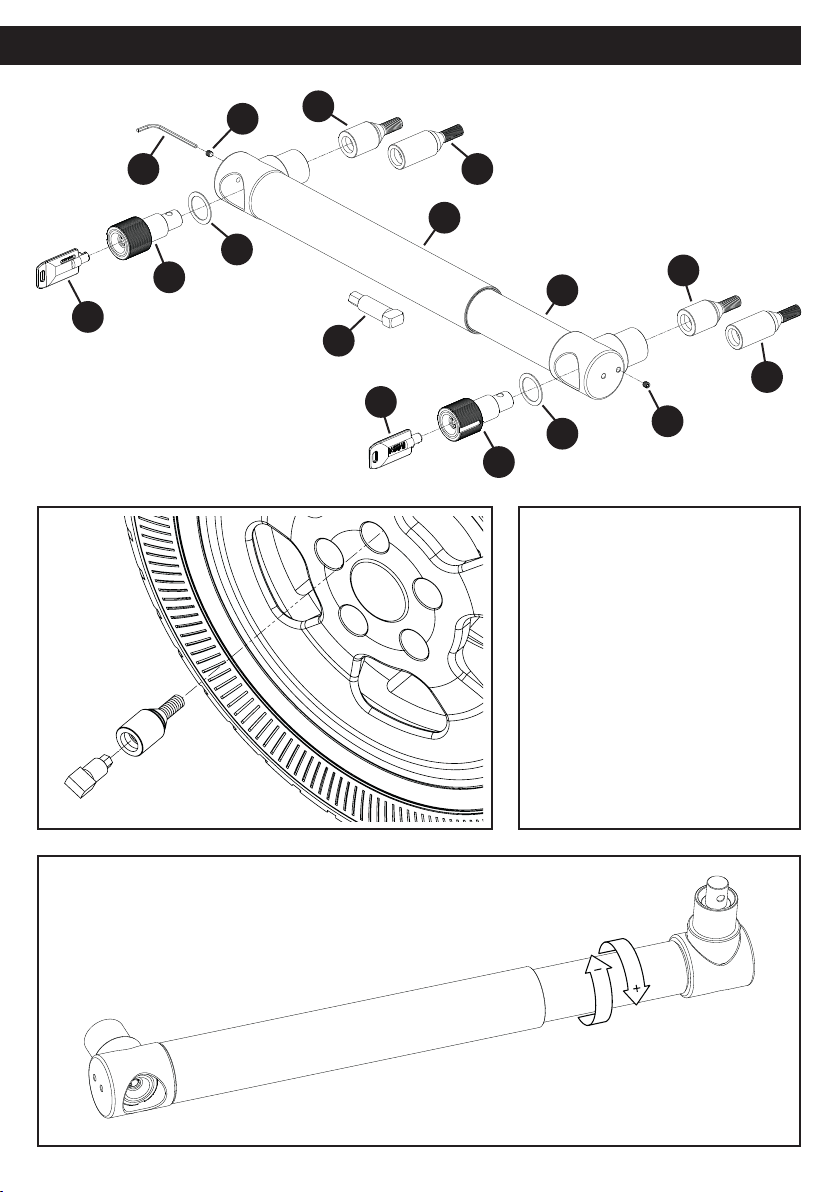
2. To prepare the Gemini for tting, the required length must rst be determined and adjusted accordingly.
To do this, both Locking Portions (3) will need installing for use as guides. Using Fig.A for reference, install
the Locking Portions (3) into apertures in the head of both the Outer (1) and Inner Tubes (2). Each Locking
Portion (3) can then be secured in place by tightening the Locking Portion Hex Screw (5) using the supplied
3mm Hex Key (6) (see Fig.A for reference).
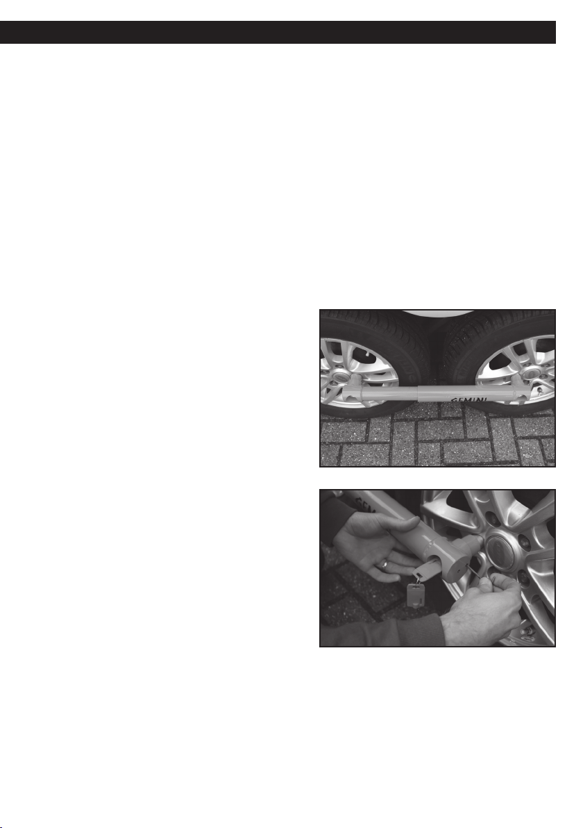
Next, hold the device up to the wheels, and line the Locking Portion (3) in the head of the Outer Tube (1) up
with the Receiver Bolt (9,10) in one of the wheels. From here, gauge whether the length of the Gemini needs
to be longer or shorter to allow the Locking Portion (3) in the head of the Inner Tube (2) to line up correctly
with the Receiver Bolt (9,10) in the second wheel (see Fig.F for guidance).
To adjust the length of the Gemini Wheel Lock to suit your vehicle, grip the Outer Tube (1) in one hand,
and proceed to rotate the Inner Tube (2) in the disired direction (see Fig.C). Use the arrow graphic on the
product for reference. Whilst adjusting the length of the Gemini, periodically oer the assembly up to the
Receiver Bolts (9,10) in order to correctly judge the required length. Each 360°rotation of the Inner Tube (2)
is approximately equal to 1.5mm of length adjustment.
NOTE: When shortening the length of the Gemini,
ensure that if resistance is met, you do not continue
to attempt shortening. This has likely occurred as
the minimum length has been met. If in this state the
assembly is too long, consider relocating the position
of your Receiver Wheel Bolts (9,10) to allow for a wider
installation length.
3. Before using the device it may be necessary to add
Spacer Rings (4) to ensure that, when tted, the ends of
the locking portion tubes are as tight as possible to the
face of the wheel when the Locking Portion (3) is locked
into a Receiver Bolt (9,10). To check this, rst t both
sets of keys (7) into their respective Locking Portions (3)
and rotate them through 90° clockwise to release the
locking ball bearings.
Oer up the assembly to the Receiver Bolts (9,10),
guiding the end of the Locking Portions (3) in as far as
they will go. Lock them together by rotating the keys (7)
anti-clockwise through 90°, then remove both keys (7).
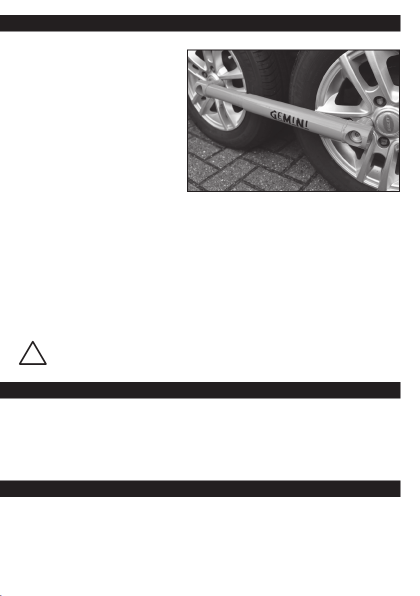
The aim at this stage is for the heads of both the Inner
(2) and Outer Tubes (1) to be as tight as possible to the
face of the wheels, when the Locking Portions (3) are
locked into the Receiver Bolts (9,10). Acheiving this will
mean that the Gemini will be most eective; protecting
and preventing acess to the Receiver Bolts (9,10) when
locked in place.
Fig. H
Fig. G
If there is a gap, or the asembly can be pulled away from the face of the wheel, making the Receiver Bolts
(9,10) visible, then Spacer Rings (4) must be used. Try to gauge the amount of gap and add the necessary
amount of 1mm thickness Spacer Rings (4) between each Tube (1,2) and respective Locking Portion (3) as
shown in Fig.A. Always add an equal sum of spacer rings (4) to each Tube (1,2) .To x these in place, use the
supplied 3mm Hex Key (6) and tighten the Locking Portion Hex Screws (5) into the most applicable of the
two avilable holes in each Tube (1,2) (see Fig.H). The Hex Screws (5) should be tightened to the bodies of the
Locking Portions (3) to correctly secure the spacer rings (4) in place.

FGT400 User Manual Page 4 UK
MAINTENANCE
PRODUCT REGISTRATION
Grease the lock face and ball bearings before rst use, with a light oil such as 3-IN-ONE or equivalent.
Thereafter spray any moving parts of the lock body with a light oil such as 3-IN-ONE or equivalent every
eight weeks.
Any light scus on the gloss surface of the body can often be bued out with a cloth.
INSTALLATION (CONT.)
Please store your keys in a safe place and remember to register your product.
Registration is quick and simple, go to www.purpleline.co.uk/product-registration
Please register within 14 days of purchase. Please retain your original purchase receipt.
NOTE: If at this stage you nd that the
Standard Receiver Bolts (9) do not
protrude far enough from the wheel to
achieve a ush t of the Gemini Lock with
the wheels, it may be that you require
the provided longer Receiver Bolts (10).
Revert back to section 1, and install the
Long Receiver Bolts (10) following the
same procedure.
4. The Gemini Twin Axle Wheel Lock is
now ready for use. Please check Receiver
Bolt (9,10) torque setting after the rst
100 miles (approx) and at regular intervals
thereafter.
During general use, the length of the Gemini Wheel Lock may need adjustment to suit various receiver
bolt locations. In these cases, adjust in the same manner as during set up (Fig.C). Once installed as per
this manual, elements such as the Spacer Rings (4) and Receiver Bolt (9,10) tting should not require
amendment, except for maintenance purposes.
NOTE: In use, some wheel rotation will occur before the Gemini Wheel Lock fully imobilises both axles, thus
preventing movement of the vehicle.
TIP: To reduce the amount of length adjustment required between each use, it is possible to add a second
Receiver Bolt (9,10) onto each wheel. When doing this, we advise locating the second Receiver Bolts (9,10)
in opposing positions to the original Reciver Bolts (9,10); this will allow for a wider range of tting positions.
As per section 1 of this manual, the lock body should still be tted to the closest two Receiver Bolts (9,10)
to prevent excess unwanted wheel rotation.
We do not recomend replacing any more than
two wheel bolts on any given wheel.
!
Fig. I

PRODUCT SPECIFICATION
FGT400
Weight (kg) Length (mm) Width (mm) Height (mm) Keys Supplied
6.5kg 550mm 60mm 100mm 4
© Copyright 2020. Purple Line Limited, Peninsula Business Centre, Wherstead, Suolk, IP9 2BB, UK
www.purpleline.co.uk
+44 1473 601200
Photographs for illustration purposes only. Actual product may dier slightly.
Purple Line Limited reserve the right to alter product specication without prior notice. design...innovate...improve
Disclaimer
If used properly, your FullStop® product will be an eective deterrent. However, nothing can stop
the eorts of the most determined thief, and to this end no liability is accepted for any loss and/or
damage caused by any illegal activity including theft or vandalism. Liability is also not accepted for
any loss and/or damage arising from misuse, unauthorised repair or alteration and failure to follow
the user guide directions. No form of consequential loss what so ever will be accepted.
This manual suits for next models
1
Table of contents
Other Purpleline Automobile Accessories manuals

Purpleline
Purpleline AEROplus APS10 User manual

Purpleline
Purpleline Saracen SHL400 User manual

Purpleline
Purpleline Nemesis Ultra FNU200 User manual

Purpleline
Purpleline FullStop Nemesis Ultra FNU200 Assembly instructions

Purpleline
Purpleline Ego QuicKEY SGO130 User manual

Purpleline
Purpleline Nemesis Ultra FNU100 User manual

Purpleline
Purpleline Quattro Titanium User manual

Purpleline
Purpleline fullstop NEMESIS FPC100 Assembly instructions