STEINBAUER 220819 User manual

The Emo t ionof M o t i o n
220819
-
STEINBAUER versteht sich als innovativer, markenunabhängiger Anbieter von elektronischen Kom
-
ponenten und Zusatzmodulen im weltweiten Fahrzeugmarkt. Erklärtes Ziel ist es Resultate zu liefern,
nicht nur Produkte.
Danke, dass Sie sich für den Kauf eines STEINBAUER Produktes entschieden haben.
STEINBAUER is an innovative manufacturer of electronic components and additional modules for the
worldwide vehicle market. Our aim is to supply you with results, not only products.
Thank you for choosing to buy from STEINBAUER.
FIRMENHAUPTSITZ:
HEADQUARTERS:
STEINBAUER
Performance Austria GmbH
Betriebsstraße 21
4224 Wartberg ob der Aist
T: +43 - 7236-21 8 21- 0
F: +43 - 7236-21 8 21- 40
E: info.at@steinbauer.cc
HAUPTSITZ USA:
HEAD OFFICE USA:
STEINBAUER
Performance LLC,
364 Crompton Street
Charlotte NC 28273
T: +1 (704) 587 - 0856
F: +1 (704) 587 - 0896
E: usa@steinbauer.cc
HAUPTSITZ UK:
HEAD OFFICE UK:
STEINBAUER
Tuning Technologies UK Ltd.
Llamedos, Hay Green Rd. South
TSC, Kings Lynn, Norfolk PE34 4PU, U.K.
T: +44 (0) 1553 - 82 99 90
F: +44 (0) 1553 - 88 64 06
E: sales@steinbauer.cc
www.steinbauer.cc
HINWEIS: Bei Einbau erlischt die freiwillige Herstellergarantie. NOTE: Usage of our products causes the expiry of the manufacturer´s warranty.
Wichtige Hinweise
Um auch langfristig die technischen Vorteile Ihrer neu erworbenen STEINBAUER Zusatzelektronik
nutzen zu können, bitten wir Sie folgende Hinweise zu berücksichtigen. Nehmen Sie die STEINBAUER
Zusatzelektronik nicht in Betrieb bevor Sie die Hinweise gelesen und verstanden haben.
Der Einbau bestätigt, dass der Käufer die Hinweise gelesen, verstanden und akzeptiert hat.
Wir empfehlen, den Einbau der STEINBAUER Zusatzelektronik von einer Fachwerkstatt vornehmen zu
lassen. Lesen Sie vor dem Einbau alle
Anweisungen genau durch.
Bauen Sie die STEINBAUER Elektronik NICHT ein, solange die Zün-
dung läuft oder der Zündschlüssel steckt! Es wird empfohlen, die
Batterie vor dem Einbau abzuklemmen; es ist erforderlich, dass sich
das Original Motorsteuergerät im absoluten Ruhezustand befindet.
Befestigen Sie den STEINBAUER Kabelsatz mit Kabelbindern, um
etwaige Beschädigungen und die damit verbundenen Funktions-
störungen zu verhindern.
Achten Sie besonders darauf, dass die STEINBAUER Zusatzelek-
tronik nicht an Metallteilen anliegt oder scheuert.
Die STEINBAUER Zusatzelektronik an einem geeigneten Ort ver-
stauen bzw. befestigen an dem keine originalen Teile beeinflusst
oder beschädigt werden.
Die STEINBAUER Zusatzelektronik so befestigen dass keine Schäden
am Fahrzeug hervorgerufen werden.
Falls Funktionsstörungen aufgrund nicht befestigter Kabel oder
eines nicht ordnungsgemäßen Einbaus der STEINBAUER Zu-
satzelektronik auftreten, erlischt die Herstellergarantie und
die Haftung für Folgeschäden der STEINBAUER Austria GmbH.
Bei sachgerechter Anwendung gewähren wir 3 Jahre Garantie ab
Auslieferung auf Ihre STEINBAUER Zusatzelektronik.
Sollten beim Einbau Unklarheiten auftreten, kontaktieren Sie
bitte STEINBAUER Austria oder Ihren nächsten Vertriebspartner.
Sie sind für den Einbau selber verantwortlich.
Als Hersteller der STEINBAUER Zusatzelektronik sind wir verpflich-
tet Sie darauf hinzuweisen, dass jegliche Veränderungen, die Sie am
für den öffentlichen Verkehr zugelassenen Fahrzeug vornehmen,
der Abnahme durch eine Prüfstelle und der Eintragung in die Fahr-
zeugpapiere bedarf.
Die gesetzlichen Bestimmungen sind allerdings von Land zu Land
unterschiedlich, daher bitten wir Sie sich bei den zuständigen Be-
hörden zu erkundigen.
Bitte beachten Sie unsere allgemeinen Geschäftsbedingungen.
Beim Einbau ist unbedingt darauf zu achten, scharfe Kanten zu
vermeinden, da dadurch der Kabelsatz besschädigt werden kann.
DO NOT install the STEINBAUER additional electronic with the
ignition turned on or the key in the ignition slot.
We recommend to disconnect the battery prior to installation; it is
important that the vehicle ECU has stopped completely.
To avoid any damages and therefore caused malfunctions,
x the STEINBAUER wiring loom with cable fasteners. Take care that
the STEINBAUER wiring loom does not touch or rub on metal parts.
In case of malfunctions caused by not xed cables or by inappro-
priate installation the STEINBAUER manufacturer’s guarantee and
liability for consequential damage of STEINBAUER Austria GmbH
expires. We grant a three years’ guarantee starting at dispatch, but
only in case of appropriate installation and usage.
If you have any questions when installing, please do not hesitate
to contact STEINBAUER Austria or your nearest sales partner.
As manufacturer of the STEINBAUER Additional electronic we are
obliged to inform you, that any changes made to a vehicle licensed
for public transport, must be notied to the appropriate inspection
authority and inserted to the car documents.
The legal restrictions are dierent in each country,
therefore please check with appropriate authority.
Please read our general terms.
During installation, care should be taken to ensure that product
cables are located away from sharp edges and excessive friction to
avoid possible damage to internal wiring.
Important information
To be able to take the benets of all technical advantages of your newly purchased STEINBAUER
Additional electronic, please consider the following advices. Do not use the STEINBAUER Additional
electronic before you have read and understood the “Important information”. The installation con-
rms that the buyer has read, understood and accepted the “Important information”. We recommend
that the installation of the STEINBAUER additional electronic is carried out by an authorized work-
shop that is familiar with the installation of our product. Please read all instructions
carefully before installation.

www.steinbauer.cc
NEHMEN SIE DIE STEINBAUER ZUSATZELEKTRONIK NICHT IN BETRIEB BEVOR SIE DIE WICHTIGEN HINWEISE
GELESEN UND VERSTANDEN HABEN.
DO NOT USE THE STEINBAUER POWER ENHANCEMENT BEFORE YOU HAVE READ AND UNDERSTOOD THE
„IMPORTANT INFORMATION“.
HINWEIS: Bei Einbau erlischt die freiwillige Herstellergarantie. NOTE: Usage of our products causes the expiry of the manufacturer´s warranty.
1Lösen Sie die Steckverbindungen am Motor. Anheben des Fahrzeugs kann erforderlich sein, um den Ladedrucksensor 1 zu erreichen.
Disconnect the marked connections on the engine. Lifting the vehicle may be necessary to gain access to Boost Pressure Sensor 1.
2Die Stecker des STEINBAUER Kabelsatz zwischenstecken und verriegeln.
Plug the connectors of the STEINBAUER wiring harness in between the original cables and the engine connectors and lock them.
3Rote Leitung an +12V und schwarze Leitung an Batterie Minus (-) schließen.
Connect the red wire to the Positive (+) battery terminal and the black wire to the Negative (-) battery terminal.
4STEINBAUER Leistungsoptimierung im Motorraum verstauen.
Stow the STEINBAUER Power Module in the engine bay.
Einbau / Installation
SIEHE„WICHTIGE HINWEISE“.
SEE “IMPORTANT INFORMATION”.
Funktionsweise
Die STEINBAUER Leistungsoptimierung verlängert je nach Bedarf die Haupteinspritzung nach einer von uns vorgegebenen Kennlinie. Dabei
wird die Originaleinspritzmenge am Fahrzeug aufgenommen, Drehzahl und Einspritzmengen berechnet und aus den Ergebnissen und den
gespeicherten Kennfeldern wird der Lastzustand berechnet. Je nach Lastzustand und gespeichertem Kennfeld wird die Mehrmenge berech-
net und die Originaleinspritzung entsprechend verändert.
How it works
The STEINBAUER Power enhancement modifies the injection system by fine tuning the duration of the injectors.
This is achieved by blue printing the original characteristics and intercepting the electronic signals from the ECU to the injection system. The
fuel injection and engine speed are recorded and recalculated to optimize performance.
Einbau / Installation
Batterie
Battery
Ladedrucksensor 2
Boost Pressure Sensor 2
Ladedrucksensor 1
Boost Pressure Sensor 1
Raildrucksensor
Rail Pressure Sensor
Bitte unbedingt beachten, dass der Kabelbaum sicher bei den
beweglichen Teilen (Riemen, etc..) vorbeiführt!
Make sure the harness passes safely by
the alternator pulley and the engine belt!
Turboregelventil
Turbo Control Valve
Nockenwellensensor
Camshaft Sensor
1
1
1
1
1
2
2
2
2
2
3
220819
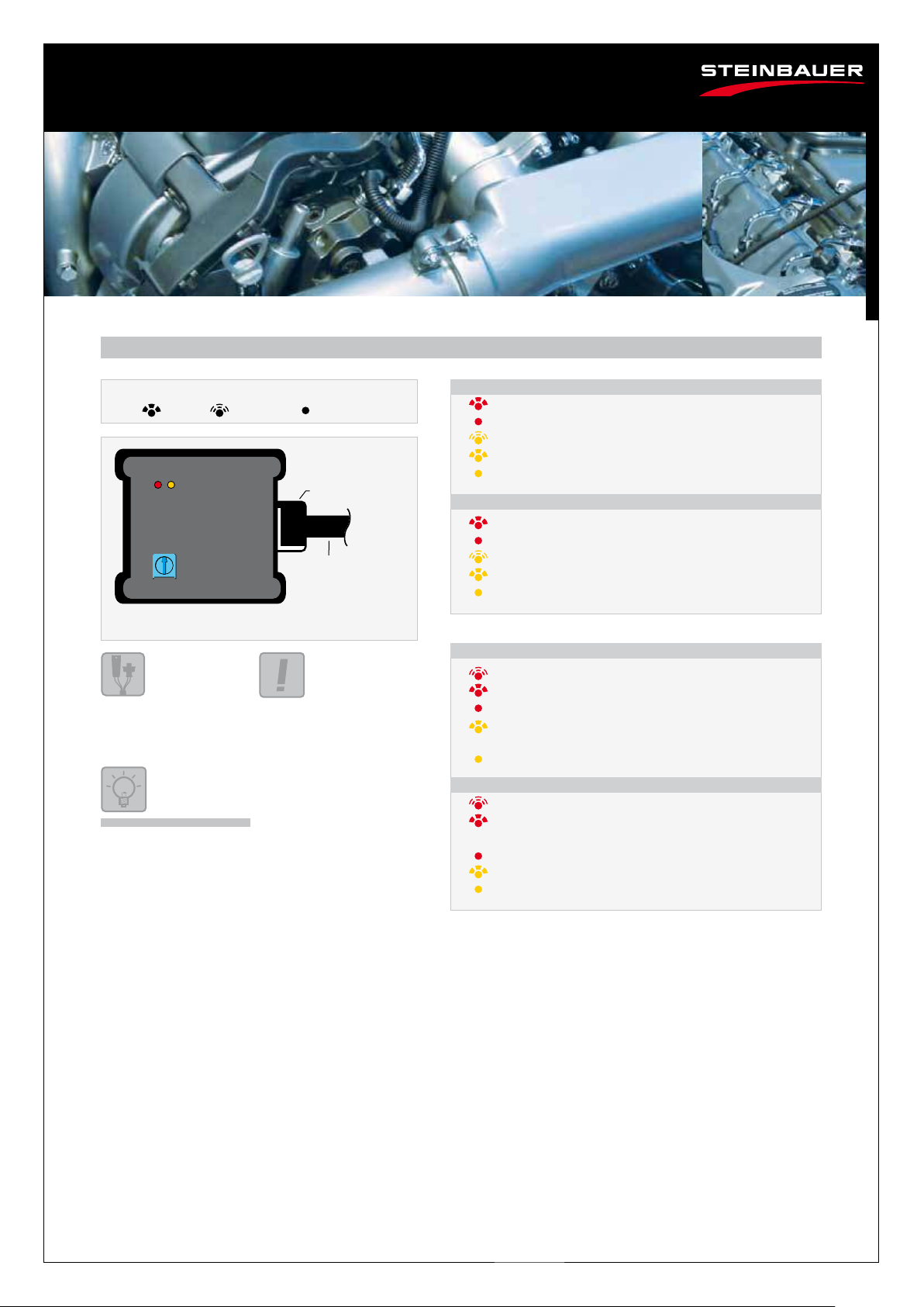
rt - Spannungsversorgung korrekt
rt - Spannungsversorgung falsch angeschlossen oder Elektronik defekt
ge - Referenzsignal richtig angeschlossen
ge - Referenzsignal falsch angeschlossen (> 5V)
ge Referenzsignal falsch angeschlossen (< 0,5V)
rt - die Blinkfrequenz erhöht sich mit der Motordrehzahl
rt - Kabelsatz kontrollieren, wenn richtig installiert
rt - Elektronik defekt
ge - Select-Leitung auf Masse bzw. Schalterstellung geschlossen =
Serienleistung
- Select-Leitung offen, Schalterstellung offen = Mehrleistung
rt - the ashing frequency raises according to engine speed
rt - check wiring loom; if it is installed correct,
the electronic is defect
rt - electronic is defect
ge - Switch in closed position (o) = original power
ge - Switch in open position (on) = power enhancement
rt - power supply is correct
rt - power supply is not correct or electronic is defect
ge - Reference signal is connected correct
ge - Reference signal is connected incorrect (> 5 V)
ge - Reference signal is connected incorrect (< 0,5 V)
Symbolerklärung / Explanation of symbols
LED: = an / on = blinkt / ashes = aus / o
HINWEIS: Bei Einbau erlischt die freiwillige Herstellergarantie. NOTE: Usage of our products causes the expiry of the manufacturer´s warranty.
STEINBAUER Zusatzelektronik ohne Deckel
Stecker
Kabelsatz
Potentiometer
LEDs
Symbol
ge = gelb / yellow rt= rot / red
Farbabkürzungen / Colour abbreviations
Mit passendem Werkzeug den
Deckel der STEINBAUER Zusatz-
elektronik öffnen.
Open the STEINBAUER Additional
electronic with the appropriate tool.
Einbauposition des Potentiometers
kann variieren.
The position of the
potentiometer may vary.
STEINBAUER Additional electronic without cover
Connector
Wiring loom
1) Zündung einschalten. (Motor nicht starten)
2) Motor starten.
1) Ignition on (do not start engine)
2) Start engine.
Funktionskontrolle / Control of function
(Abdeckung der Box abschrauben / remove the cover of the module)
ge
www.steinbauer.cc

Feinabstimmung der STEINBAUER Zusatzelektronik
Aufgrund von Serientoleranzen kann es dazu kommen, dass die voreingestellte Kennlinie der STEINBAUER Zusatzelektronik zu viel oder
zu wenig Mehrleistung bewirkt. Eine zu hoch eingestellte Kennlinie verursacht Motoraussetzer, unruhigen Motorleerlauf (Drehzahl-
schwankungen), „Ruckeln“, Abschalten oder Notlauf des Motors (stark verringerte Leistung) oder Aufleuchten der Fehlerkontrollleuchte.
Diese Beanstandungen können Sie durch Feinabstimmung der STEINBAUER Zusatzelektronik mittels Potentiometer beheben.
Die Potentiometer-Einstellung hat wenig Auswirkung auf die Mehrleistung, lediglich auf die Abgaswerte.
Fine adjustment of the STEINBAUER Additional electronic
Due to original tolerances of manufacturing the preset characteristic map of the STEINBAUER Additional electronic may oers too much
or too less power enhancement. An inated characteristic map causes engine misres, bumpy idle running (variations of revolution
speed), “bucking”, stop or emergency mode of engine (severe less power) or ashing of defect control lights. You can remedy these
defects by ne adjustment of the STEINBAUER Additional electronic with the Potentiometer. The adjustment of the Potentiometer does
not adversely eect the power enhancement.
Potentiometer
HINWEIS: Bei Einbau erlischt die freiwillige Herstellergarantie. NOTE: Usage of our products causes the expiry of the manufacturer´s warranty.
STEINBAUER Zusatzelektronik ohne Deckel
Stecker
Kabelsatz
Symbol
12 Uhr
tweleve o´clock
100 %
rechter Anschlag
totally right
130 %
linker Anschlag
totally left
50 %
Einbauposition des Potentio-
meters kann variieren.
The position of the
potentiometer may vary.
Mit passendem Werkzeug den Deckel
der STEINBAUER Zusatzelektronik öffnen.
Open the STEINBAUER Additional
electronic with the appropriate tool.
STEINBAUER Additional electronic without cover
Connector
Wiring loom
Normale Kennlinie
Erhöhung der Kennlinie
Reduzierung der Kennlinie
Das Potentiometer etwas nach links (gegen den Uhrzeigersinn)
drehen.
Probefahrt machen.
Den Vorgang wiederholen bis keine Beanstandungen mehr auftreten.
Das Potentiometer etwas nach rechts (im Uhrzeigersinn) drehen.
Probefahrt machen.
Den Vorgang wiederholen bis keine Beanstandungen mehr auftreten.
Turn the potentiometer to the right in small steps (clockwise).
Have a test-drive.
Repeat this procedure until all problems are solved.
Turn the potentiometer to the left in small steps (anti-clockwise).
Have a test-drive.
Repeat this procedure until all problems are solved.
Enhancement of the characteristic map
Reduction of the characteristic map
Mit dem Potentiometer kann die Feinabstimmung durchgeführt werden.
Die Grafik zeigt die Potentiometer Standardeinstellung ab Werk, normale
Kennlinie = 100%.
! Normale Kennlinie = Original Leistung +20% !
The ne adjustment can be done with the potentiometer.
The gure shows the standard adjustment of the potentiometer
made at production, normal characteristic map = 100%.
!Normal characteristic map = Original power enhancement +20%!
Normal characteristic map
Einstellen der Kennlinie / Adjustment of the characteristic map (Abdeckung der Box abschrauben / remove the cover of the module)
www.steinbauer.cc
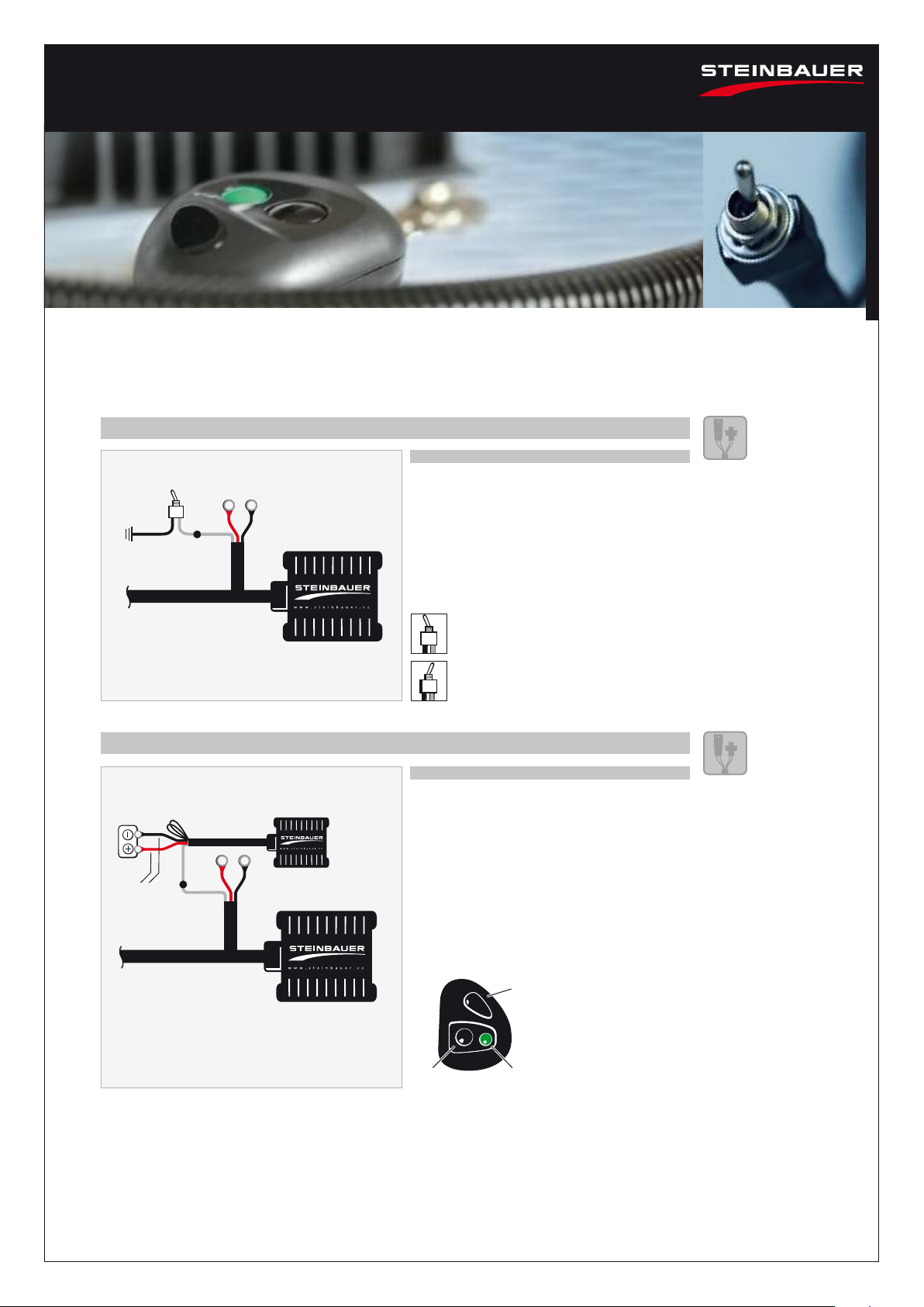
STEINBAUER Zusatzelektronik
STEINBAUER Additional electronic
STEINBAUER Kippschalter
STEINBAUER Switch
Mehrleistung
Power enhancement
Serienleistung
Original power
LED
Batterie
Battery
STEINBAUER
Funkfern-
bedienung
STEINBAUER
Remote Control
Leitungen für
Spannungsversorgung
Wires for power supply
STEINBAUER Funkhandsender
STEINBAUER Transmitter
Select-
Leitung
Switch wire
STEINBAUER Zusatzelektronik
STEINBAUER Additional electronic
Select-
Leitung
Switch
wire
Masse
Battery Negative (-)
terminal
(chassis ground)
Zubehör / Accessories
Zum Ein-/Ausschalten der STEINBAUER Zusatzelektronik.
To turn on/othe STEINBAUER Additonal electronic.
HINWEIS: Bei Einbau erlischt die freiwillige Herstellergarantie. NOTE: Usage of our products causes the expiry of the manufacturer´s warranty.
Kippschalter kann separat
bestellt werden.
Artikelnummer 200086.
You can order
the switch separately.
Part no. 200086.
Funkfernbedienung kann
separat bestellt werden.
Artikelnummer 200089.
You can order the
remote control separately.
Part no. 200089.
Mehrleistung: Schalterstellung oen
Power enhancement: Switch in open
position
Mehrleistung:
Schwarze Taste drücken
Power enhancement:
Press the black button
Serienleistung:
Grüne Taste drücken
Original power:
Press the green button
Serienleistung: Schalterstellung geschlossen
Original power: Switch in closed position
Die graue Leitung vom Kippschalter an die
Select-Leitung (graue Leitung der STEINBAUER
Zusatzelektronik) schließen. Die schwarze Leitung
an Batterie Minus (Masse) schließen.
Connect the grey wire of the switch to the Switch wire
(grey wire of the STEINBAUER Additional electronic).
Connect the black wire of the switch to the battery
Negative (-) terminal (chassis ground).
Rote Leitung an Batterie Plus, schwarze Leitung
an Batterie Minus (Masse) schließen.
Die graue Leitung der Funkfernbedienung an die
Select-Leitung (graue Leitung der STEINBAUER
Zusatzelektronik) schließen.
Connect the red wire to the battery Positive (+) ter-
minal, black wire to the battery Negative (-) terminal.
Connect the grey wire of the remote control to the
Switch wire (grey wire of the STEINBAUER Additonal
electronic).
Kippschalter / Switch
Funkfernbedienung / Remote Control
Einbau / Installation
Einbau / Installation
www.steinbauer.cc

AT 12/14 Copyright © 2014 STEINBAUER Performance Austria GmbH. Änderungen, bedingt durch ständige Innovation, vorbehalten. Design und Konzept © STEINBAUERMEDIA.com. Subject to change. All rights reserved. Design and Concept © STEINBAUERMEDIA.com
FIRMENHAUPTSITZ:
HEADQUARTERS:
STEINBAUER
Performance Austria GmbH
Betriebsstraße 21
4224 Wartberg ob der Aist
T: +43 - 7236-21 8 21- 0
F: +43 - 7236-21 8 21- 40
E: info.at@steinbauer.cc
Table of contents
Other STEINBAUER Automobile Accessories manuals

STEINBAUER
STEINBAUER 220595 User manual

STEINBAUER
STEINBAUER 220733 User manual

STEINBAUER
STEINBAUER 220629 User manual

STEINBAUER
STEINBAUER 220735 User manual

STEINBAUER
STEINBAUER 220181 User manual

STEINBAUER
STEINBAUER 230159 User manual

STEINBAUER
STEINBAUER 220175 User manual

STEINBAUER
STEINBAUER 220412 Operating manual
Popular Automobile Accessories manuals by other brands


Clifford
Clifford NightVision operating instructions

E&G Classics
E&G Classics Black Ice Mesh instruction manual

DV8 OFFROAD
DV8 OFFROAD WINCH POCKET FAIRLEAD Product installation manual

iOttie
iOttie iTap 2 Wireless manual

Renault
Renault 77 11 426 186 installation instructions

Veldo Teknoloji
Veldo Teknoloji DUCATO manual