Introduction
The Aeroplus® is designed to drive the ow of air more smoothly over the top of your caravan
- reducing drag, increasing towing stability and increasing fuel economy.
Please read this User Guide fully prior to use and retain for future reference.
12
H
G
F
E
D
C
B
A
J
K
L
M
N
P
Q
R
A
B
C
D
E
F
G
H
J
K
L
M
N
P
Q
11
10
9
8
7
6
5
4
3
2
1
13
14
15
16
17
18
19
20
21
22
23
24
1
2
3
4
5
6
7
8
9
10
11
12
13
14
15
16
17
18
19
20
AP bracket exploded
WEIGHT:
A0
SHEET 1 OF 1
SCALE:1:5
DWG NO.
TITLE:
REVISION
DO NOT SCALE DRAWING
MATERIAL:
DATE
SIGNATURE
NAME
DEBUR AND
BREAK SHARP
EDGES
FINISH:
UNLESS OTHERWISE SPECIFIED:
DIMENSIONS ARE IN MILLIMETERS
SURFACE FINISH:
TOLERANCES:
LINEAR:
ANGULAR:
Q.A
MFG
APPV'D
CHK'D
DRAWN
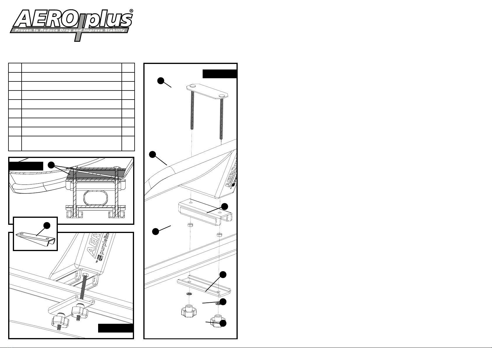
Ref. Part Description Qty
AAeroplus® Deector 1
B Upper Bracket Plate with integral bolts 2
CMiddle Bracket 2
DNylock Nuts 4
E Lower Bracket 2
F Spring Washers 4
GPlastic Knobs 4
H Angle Adjustment Spacers (not included
-available to purchase separately)
4
Diagram 1
Diagram 2
A
B
C
D
E
F
G
Diagram 3
H
H
Cross-Section of
Clamp Assembly
Assembly
The Aeroplus® brackets are designed to t onto most standard roof bars with a bar height up to
35mm. Note: If the optional Angle Adjustment Spacers (H) are utilised the overall height of the
clamp assembly is increased by approx. 20mm, so please ensure there is enough thread on the
Upper Bracket Bolts (B) to securely attach the deector.
Prior to Aeroplus® tment, attach a suitable roof bar to the rear of your vehicle. If your vehicle
is tted with longitudinal roof rails (present on some 4x4s, estate cars and MPVs), you should
attach the roof bar as far as possible towards the rear of the vehicle. (please see Diagram 4 for
guidance).
To t the Aeroplus®, start by tting the Upper Bracket Bolts (B) through the apertures on both
mounting points on the Aeroplus® (A), t the Middle Brackets (C) and secure with the Nylock nuts
(D) .
Position the Aeroplus® central to the width of the roof bar and secure with the Lower Brackets
(E), the Spring Washers (F) and the Knobs (G). Ensure all xings are suitably secure.
The Aeroplus® is now ready for use. Note: Remember to remove from your car when you are not
towing your caravan.
To remove, reverse the procedure on parts (E), (F) and (G). Keep the loose components in a safe
place.
Fitment of Optional Angle Adjustment Spacers
The Spacers (H) will alter the default angle of the Aeroplus™ by ±10° degrees approximately. In
order to optimise performance, it may be necessary to make alterations, as every car/caravan
set-up is dierent.
If required, t the Spacers (H), one in-between the Aeroplus® (A) and the Upper Bracket (B) and
one in-between the underside of the Aeroplus® (A) and the Middle Bracket (C) . If the angle needs
to be steeper, t the top Spacer (H) with the thick end facing the front of the vehicle, to reduce the
angle, reverse the Spacer (please see Diagrams 3 & 5).
A set of Angle Adjustment Spacers are available direct from Purple Line Limited for £14.99
including V
A
T
, post and packaging. Please call 01473 601200 or e-mail:
[email protected].
cont. overleaf


