Purus Pro Line User manual

Installation instructions
Purus Pro Line gratings
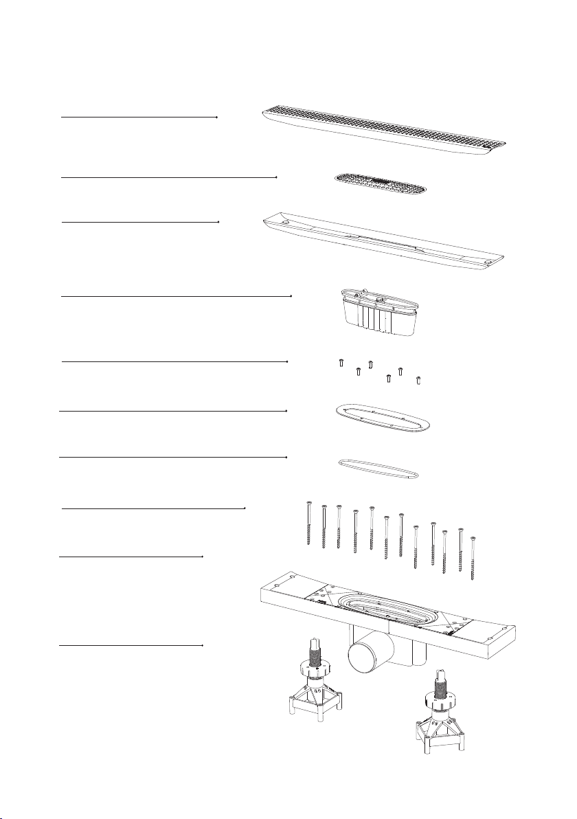
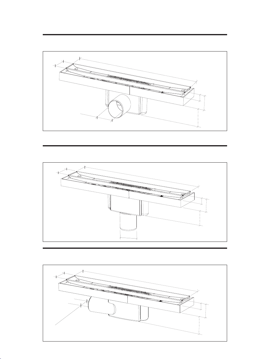
Installing floor gully
The floor gully must be installed in accordance
with current industry regulations. We recom-
mend that installation is carried out by an
authorized plumbing company.
The floor gully must be installed horizontally
and at the right level with the sealing layer, with
a horizontal tolerance of +/- 2 mm measured
from the centre of the gully to the flange's
outer edge. In wooden joists, the floor gully
is anchored using the supplied screws. Purus
stabilisers are used in cast floors. The floor
gully's protective foil must not be removed
during installation.
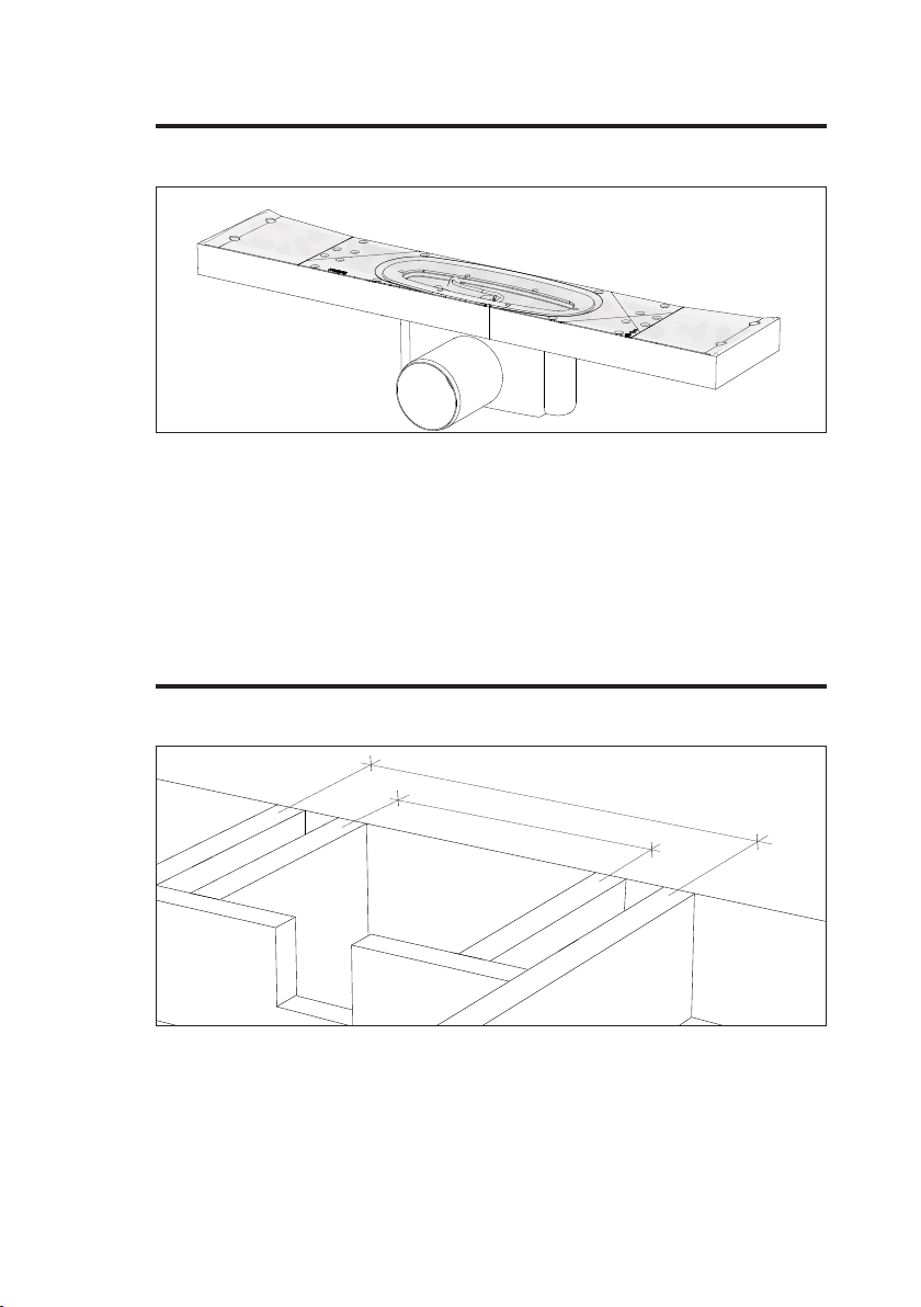
For installation near walls
Purus Pro LIne is installed close to the wall, in
a combination of floor gully and sealing layer,
a membrane must be used in conjunction
with the various drain types that have SINTEF
Technical Approval. The membrane with
accompanying gully rubber connector is laid
in accordance with the membrane supplier's
installation instructions and as shown in the
various instructions for the Purus Pro Line.
Monteringsanvisning
Purus Pro Line med rist
Montasje av gulvsluk
Gulvsluket skal installeres i.h.t gjeldende
bransjeregler. Vi anbefaler at installasjonen
gjøres av ett autorisert VVS firma.
Gulvsluket skal monteres vannrett og i rett niva
med tettesjiktet, med en toleranse vannrett på
+/- 2 mm målt fra slukets senter til flensens yt-
terkant. I trebjelkelag skal gulvsluket forankres
med de med følgende skruer. I helstøpt gulv
benyttes Purus støtteben. Gulvslukets beskyt-
telsefolie skal ikke fjernes under installasjon.
Veggnær installasjon
Purus Pro Line installeres veggnært, i
kombinasjon av gulvsluk og tettesjikt skal
det brukes membran i samhørighet med de
ulike sluktypene som har en SINTEF Teknisk
Godkjenning. Membran med tilhørende sluk-
mansjett legges i .h.t membranleverandørens
monteringanvisning og som vist i de ulike
anvisningene for Purus Pro Line.
www.purus.no

Purus Pro Line med rist
Purus Pro Line grating
Trebjelkelag/Wooden joist
Purus Pro Line med rist
Purus Pro Line grating
Betong/Concrete
Innholdsfortegnelse
Table of content
Purus Pro Line med rist/Purus Pro Line grating 3
Forberedelser før installasjon/Preparation before installation 4
Dimensjoner/Dimensions 5, 6
Montering betong/Installation concrete 7, 8
Montering trebjelkelag/Installation wooden joist 9, 10,11
Fallsparkle-montering til ferdig gulv/Installation concrete/wooden joist 12, 13,14
Tilbehør/Accessories 15
2

1. Rist
Grating
3. Ramme
Frame
9. Sluk
Drain
6. Klemring
Clamping ring
5. PT skrue, 6 stk.
Plastic screw, 6 pcs
4. Vannlås
Water trap
2. Hårsil
Strainer
10. Purus støtteben, 2 stk
Purus support, 2 pcs
7. O-ring
O-ring
8. Treskrue, 12 stk
Screw, 12 pcs
Purus Pro Line med rist
Purus Pro Line grating
3

597/697/797/897/997/1197
10
44
73
96
Ø75/50
Gavel 75/50
10 44
73
96
597/697/797/897/997/1197
Ø75/50
Ø75
Botten 75
597/697/797/897/997/1197
10 44
73
96
Forberedelse før installasjon
Preparation before installation
Bunn 75 - Bottom 75
Gavl 75/50 - Gable 75/50
Side 75/50 - Side 75/50
4

1
2
6
6
20
/7
20/820
/
9
2
0
/
1
0
20
/122
0
585
/
685/785/885/985/1185
6
6
34
597/697/797/897/997/1197
10
44
73
35
Ø50/40
*Kun for innstøping. Only for concrete joists.
Lav side 50/40/ - Low side 50/40
Rammen skal plasseres slik at vannlåsen kan tas ut.
The frame must be positioned so the water trap can be removed!
5

7-22
5-20
7-22
7-22
12 12
Mål referer avstand fra rammen til "rå" vegg med plass for membran, lim og flis.
Measurements refer to the distance to the wall for sealing membrane, fixing
compound and tiles.
Mål referer avstand fra rammen til "rå" vegg med plass for membran, lim og flis.
Measurements refer to the distance to the wall for sealing membrane, fixing
compound and tiles.
Hjørne/Corner
Mot vegg/Against wall
Mål referer avstand fra rammen til "rå" vegg med plass for membran, lim og flis.
Measurements refer to the distance to the wall for sealing membrane, fixing
compound and tiles.
Dusjnisje/Shower niche
6

Trykk Purus støtteben på sluket og juster til ønsket høyde. Lengdene 900-1200 har
fire hull for feste av Purus støtteben, benytt kun hullene som er ytterst.
Press the Purus supporting legs onto the gully. Check that they are properly secured
and adjust to the required height. The lengths 900-1200 have four holes for at-
taching the Purus supporting legs, use the outermost holes.
Montering i betong
Installation in concrete
1
Beskyttelsefolien skal ikke fjernes under monteringen.
The protective film must remain in place during installation.
2
7

>500
4
Plasser sluket og koble til avløpsrører. Kontroller at sluket er i vater.
Position the gully and connect the soil pipe connector, sure the gully is level then
anchor the gully using the Purus supporting legs and fill the recess with concrete.
Utsparingsmål tilpasses bredden på sluket.
The width of the recess is adapted to suit the gully. We recommend that you use two
angles to create a gap to increase the possibility of adjustment.
3
Montering i betong
Installation in concrete
8

c/c 400
c
/c
6
00, 70
0,
8
0
0, 900,
1000, 1200
Beskyttelsesfolien skal sitte på under hele monteringen.
Ensure that the protective cover remains throughout the installation.
Forsterk bjelkelaget med losholt av samme dimensjon som gulvbjelkene.
Reinforce the wooden joist with the necessary noggings of the same dimension as
the joists.
1
2
Montering i trebjelkelag
Installation in wooden joist
9

x
Montering i trebjelkelag
Installation in wooden joist
Maks høyde x
Maxium height x
-Ø50 lav side (ikke for trebjelkelag)/Ø50 low side (not wooden)
35 mm Ø50 side/Ø50 side
35 mm Ø50 gavl/Ø50 gable
10 mm Ø75 side/Ø75 side
10 mm Ø75 gavl/Ø75 gable
∞Ø75 bunn/Ø75 bottom
Forhøyet montasje
Elevated mounting
Kontroller at sluket sitter vannrett og koble til avløpsrøret
Make sure the gully is level and attach the soil pipe connector.
3
10

Legg på en 22 mm sponplate med åpning tilpasset slukets mål.
Add a 22 mm chipboard with aperture adapted to the size of the drain.
Montering i trebjelkelag
Installation in wooden joist
5
Sluket monteres direkte på trebjelkelaget medfølgende treskruer. Toppkant av sluket
skal være i nivå med ferdig gulv, dvs på nivå med slukmansjett. Sluket monteres
direkte mot "rå" vegg.
Install the gully directly onto the wooden joist using wood screws and against a raw
wall.
4
11

1x
6x
Fallsparkle-montering til ferdig gulv
Installation concrete/wooden joist
Sparkle fallet til kanten av sluket 10-20 mm/m (1:100-1:50)
Apply screed to the slope to the edge of the gully 10-20 mm/m (1:100-1:50).
Fjern beskyttelsesfolien, løft opp klemringen og plukk ut posen som inneholder 1
stk. o-ring og 6 stk PT skruer for klemring.
Remove the protective foil, lift out the clamping ring and remove the bag containing 1
o-ring and 6 screws.
1
2
12

5
Membran med tilhørende slukmansjett legges i.h.t membranleverandøren monte-
ringsanvisning. I kombinasjon av gulvsluk og tettesjikt skal det brukes en membran i
samhørighet med de ulike sluktypene som har en SINTEF Teknisk Godkjenning.
The membrane with accompanying gully rubber connector is laid in accordance with
the membrane supplier's installation instructions. In combination with a floor gully
and sealing layer, a membrane must be used in conjunction with the various drain
types that have SINTEF Technical Approval.
Skjær med en kniv langs innsiden av klemringen slik at ingen membran stikker ut.
Kontroller renskjæringen ved å sjekke at vannlåsen går å løftes opp.
Using a knife, cut along the inside of the clamping ring so that no sealing
membrane protrudes. Check the cut by lifting the water trap out of the gully.
Monter O-ringen i sitt sete. Mount the O-ring in it’s place.
Fallsparkle-montering til ferdig gulv
Installation concrete/wooden joist
3
4
3
Skruva fast brunnen i monter-
ingsramen där inga reglar nns
för att förankra plastöverdelen till
ramen.
Koppla avloppet till avlopps-
ledningen.
Golvspånplattan läggs.
Checklista
Purus Line skall vara
monterad i våg.
Tätskikt skall anslutas till
Purus Line enligt tätskikts-
leverantörens anvisningar.
Den medföljande ingjutnings-
xturen monteras på
golvbrunnen.
Det nns 4 markerade skruvhål
i brunnen som passar till de
4 hål placerade närmast
centrum på xturen.
En skruv i varje ände fästs till
spånplattan.
OBS!
Är det en spårad spånplatta för
golvvärme, markera rörläggningen
för att undvika risk för genom-
borrning.
Brunnen måste placeras
centralt under ramen.
6
5
4
5
13

Smør vannlåsens pakning før den settes i sluket, plasser hårsilen i rammen og legg
risten på plass.
Lubricate the water trap gasket, place the hair strainer in the frame and put the
strainer in position.
Rammen punktlimes fast på membranen med montagelim eller festes med
fliselimet. Om det behøves kan rammen justeres i høyden ved bruk av fliselimet.
Glue the frame to the sealing membrane using installation glue or alternatively attach
to the tile fixing compound. You can adjust the height of the frame using fixing com-
pound if necessary.
Fallsparkle-montering til ferdig gulv
Installation concrete/wooden joist
6
7
14

Veggfeste Art nr 854080
Wallbracket
Sidobiter* NRF 338 59 41 600
Counterparts* NRF 338 59 42 700
NRF 338 59 43 800
NRF 338 59 44 900
NRF 338 59 45 1000
NRF 338 59 46 1200
Tilbehør
Accessories
*Benyttes når Purus Pro Line ikke skal monteres veggnært. Used when Purus Line Pro is not installed close to a wall.
15

16
23579– Monteringsanvisning Purus Pro Line med rist - 20201109
Other manuals for Pro Line
1
Table of contents
Other Purus Plumbing Product manuals
Popular Plumbing Product manuals by other brands

Hans Grohe
Hans Grohe Talis S 160 Instructions for use/assembly instructions

miseno
miseno MNO351CP manual

Clou
Clou Freddo 5 CL/06.03.006.41.L installation instructions

Clou
Clou Kaldur CL/06.05.004.84.R installation instructions

Hans Grohe
Hans Grohe Metris S 31063821 manual

Helvex
Helvex RM-24 installation guide

American Standard
American Standard CADET 3 2383 INSTALLATION INSTRUCTIONS CARE AND MAINTENANCE

Geberit
Geberit HS30 Maintenance manual

Mueller
Mueller HG-1 Operating instructions manual

Moen
Moen TL181 Series manual

Toto
Toto LB TBS01201U Installation and owner's manual

ZACK
ZACK SCALA 40049 installation instructions